Как выбрать гостиницу для кошек
14 декабря, 2021
1 Department of Civil Engineering, Technical University of Denmark, Brovej, Building 118,
DK-2800 Kgs. Lyngby, Denmark
* Corresponding Author, sf@byg. dtu. dk
Abstract
Side-by-side tests of two small low flow SDHW systems based on mantle tanks have been carried out in a laboratory test facility. The systems are identical with exception of the circulation pumps and the solar collector loops. One of the systems is equipped with a low flow SOLAR 15-65 pump from Grundfos A/S and a so-called “lifeline” solar collector loop based on a %” copper pipe for the hot solar collector fluid pumped from the solar collector to the mantle tank and on a 5/16” copper pipe for the cold solar collector fluid pumped from the mantle tank to the solar collector. Both the hot and the cold pipes are insulated with glass fibre and enclosed by a PVC jacket with a diameter of 38 mm. The other system is equipped with a normal circulation pump for solar heating systems, SOLAR 15-40 from Grundfos A/S and a normal solar collector loop consisting of 10/8 mm copper pipes insulated with 9 mm INSUL-TUBE insulation.
The tests were carried out with the same daily hot water consumption of 100 l/day. Measurements of the thermal performance of the systems, the volume flow rates in the solar collector loops and the energy consumption of the pumps have been carried out for a measurement period of about 4 months. The measurements show that the thermal performance of the SDHW system can be increased by about 1% by replacing the normal solar collector loop with the lifeline. The extra pump energy for the system with the lifeline and the SOLAR 15-65 pump was in the measurement period higher than the extra thermal performance for the system with the lifeline and the SOLAR 15-65 pump. Consequently, the “lifeline approach” is not justified from a thermal performance point of view.
The laboratory measurements will be continued with an improved solar collector loop for the SDHW system with the SOLAR 15-65 pump. The lifeline was in July 2008 replaced with small well insulated separate copper pipes. Further measurements will elucidate if the thermal advantage by using such small pipes is large enough to compensate for the extra pump energy required by the SOLAR 15-65 pump.
Keywords: SDHW systems, low flow, laboratory test, circulation pumps, pump energy, solar collector loops
Small SDHW systems can with advantage be designed as schematically shown in figure 1.
Low flow SDHW systems based on vertical mantle tanks have a number of advantages compared to similar high flow SDHW systems based on vertical hot water tanks with a built in heat exchanger spiral [1]:
• The yearly thermal performance is increased by 10%-25% depending on the solar fraction.
• Lime deposits in the mantle tank are a factor of 2.5 lower than the lime deposits in a similar hot water tank with a built in heat exchanger spiral.
• Small pipe dimensions can be used in the solar collector loop. The installation can therefore be facilitated. For instance, small all-in-one solutions with two small pipes, pipe insulation and a wire for the control system can be used as a solar collector loop resulting in decreased cost of the solar heating system.
Further, if small pipes are used in the solar collector loop, the heat loss of the pipes can be reduced and the thermal performance of the system can be increased. In order to make use of small pipes in the solar collector loop, high pressure pumps are needed. Grundfos A/S has recently introduced such circulation pumps for solar heating systems on the market, for instance the SOLAR 15-65 pump. In this paper it is for small SDHW systems experimentally investigated how much the thermal performance is increased and how much the pump energy is increased by making use of small pipes and a high pressure pump in the solar collector loop.
|
Solar collector
Fig. 1. Schematic illustration of SDHW system based on a mantle tank. |
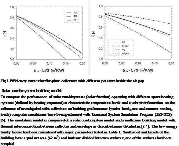
The analysis considers three types of solar collectors with different levels of pressure inside the front air gap to affect the front heat loss coefficient. Fig.1 shows the efficiency curves for idealized solar flat-plate collectors with ambient pressure (A-atmospheric collector, 100 kPa), reduced pressure (E-evacuated collector, 1 kPa) and vacuum (V-vacuum collector, 0.1 Pa, only theoretical case) obtained from mathematical model KOLEKTOR 2.2 [5]. Moreover, each variant is evaluated with three types of collector-envelope configuration (S-separate installation, R-roof integration, F — faqade integration). The thermal resistance of the envelope has been considered 6 m2K/W (low — energy house). Efficiency curves for roof and facade integration differ in the case of atmospheric collectors due to convection heat transfer reduction with higher slope of air gap in contrast to evacuated and vacuum collectors which have the convection heat transfer in the air gap completely eliminated. Further information on evacuated collector efficiency can be found in previous research
[4].
to the collector absorber (absorber temperature is identical with temperature of outer insulation layer). Splitting the envelope (roof, facade) into two surfaces allows varying the solar collector area Ac to envelope area Ae ratio (coverage factor) for parametric analysis.
Table 1. Major parameters of solar combisystem and building model.
|
Heated floor area / building volume |
150 m2 / 550 m3 |
|
Envelope U-value |
6 m2.K/W |
|
Ventilation with heat recovery |
0,3 ACH, efficiency 75 % |
|
Space heating demand Qsh |
6880 kWh/a ~ 45 kWh/m2a |
|
Space cooling demand Qsc |
2 kWh/a |
|
Storage tank volume VS |
1200 l |
|
Solar collector area Ac |
variable (1…42 m2) |
|
Average DHW demand Qdhw |
200 l/day (55/12 °C) ~ 3710 kWh/a |
|
Space heating system variants |
75/65 °C; n = 1.5 (air heating) 55/45 °C; n = 1.3 (radiators) 35/25 °C; n = 1.1 (radiant heating) |
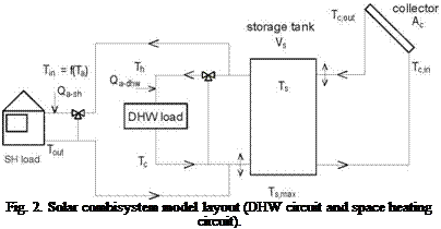 |
The solar combisystem model is based on compact integrated central heat storage tank (1200 l) with ideal stratification (variable inlets) with two heating circuits (DHW and space heating). Two auxiliary heaters were applied, first to output for DHW load (Qa-dhw) and second for space heating (Qa-sh). The combisystem model consists of idealized elements (no heat losses, no heat exchangers) to perform simulations strictly focused on energy flows and the interaction between the collector, storage tank and building environment. The schematic diagram of the solar combisystem model is shown in Fig.2.
For analysis, three different types of heating systems (air heating, radiators, radiant heating) have been considered with typical nominal operation temperatures (75/65 °C, 55/45 °C, 35/25 °C) and relevant heating exponents (n = 1.5, n = 1.3, n = 1.1). Supply temperature control according to the ambient temperature is provided. An overview of the major parameters of solar combisystem model is given in Table 1.
Principal observed parameters for the building performance were winter heat gains Aqsh and summer cooling loads Aqsc induced by collectors integrated into the envelope. For the solar system performance, solar fraction f and specific stagnation time bst have been evaluated.
The valorisation process for all results like learning of evaluation programs, guidelines, documents, complements to standards, tools developed should be as practical and efficient as possible. A website including all elements developed during this project is built (http://www. combisol. eu).
All professional actors have to be closely involved in this process of improvement of global quality of Solar CombiSystems. Consumers need to be more and better informed about these systems in order to be able to choose the most adapted system to their situation in the best conditions. Several workshops and presentations will be organised in each partner country for the different market actors.
After 8 month, the preliminary elements required for each work package are done.
• The call for Solar CombiSystem evaluation is closed, the preliminary list of systems that will be evaluated is defined.
• The common evaluation criteria data sheet is built.
• The specification for monitoring the SCS, collecting the information and evaluating the performance of the systems are done.
• The website is created.
The instrumentation of the different system, the qualitative evaluation and the test lab will start during this autumn.
This project is supported by Intelligent Energy Europe programme (http://ec. europa. eu/enemv/intelligent/index en. html)
[1] C. Bales, (2002). Combitest _ Initial Development of the AC/DC Test Method, Technical report, IEA Solar Heating & Cooling programme Task 26, http://www. iea-shc. org/task26
[2] D. J. Naron, H Visser, (2002). Development of the Direct Characterisation test procedure for Solar Combisystems, fifth draft, Technical report, IEA Solar Heating & Cooling programme Task 26, http://www. iea-shc. org/task26
[3] D. J. Naron, H Visser, (2002). Direct Characterisation Test Procedure for Solar Combisystems,
Technical report, IEA Solar Heating & Cooling programme Task 26, http://www. iea-shc. org/task26
[4] P. Vogelsanger, (2002). The Concise Cycle Test — An Indoor Test Method using a 12-day Test Cycle, Technical report, IEA Solar Heating & Cooling programme Task 26, http://www. iea-shc. org/task26
[5] H. Druck, S Bachmann (2002). Performance testing of Solar Combisystems — Comparison of the CTSS with the ACDC procedure, Technical report, IEA Solar Heating & Cooling programme Task 26, http://www. iea-shc. org/task26
[6] J. M. Suter, T. Letz, W. Weiss, J. Inabnit (2000). Solar Combisystems in Austria, Denmark, Finland, France, Germany, Sweden, Switzerland, the Netherlands and the USA-Overview 2000, IEA Solar Heating & Cooling programme Task 26, http://www. iea-shc. org/task26
[8] M. Albaric, J. Nowag, P. Papillon, (2008).Thermal performance evaluation of solar combisystem using a global approach, Eurosun 2008.
The sole responsibility for the content of this publication lies with the authors. It does not necessarily reflect the opinion of the European Communities. The European Commission is not responsible for any use that may be made of the information contained therein.
The basic components, such as boilers and collectors, are considered well-developed, but there is a need for adjustment to better suit a combined system and to offer improved and more efficient solutions to the costumer. The technical focus of development is mainly on adapted system components, such as new small boilers with smaller volumes of water, working to charge appropriate accumulator tanks, as well as integrated control systems for both solar collectors and boiler. Up to recently, the installers were forced to combine different existing components themselves, often resulting in less efficient systems. There are now efforts made to deliver complete systems. It has previously been rather complicated to purchase those systems, since different components had to be ordered from different suppliers. One important challenge is therefore the “one phone call” issue,
which was tackled by the pellet industry some years ago, but is now also raised for combined systems. It means that the costumer should only need to make one phone call, all to simplify the purchase phase and then reach a larger number of costumers.
The serious development and marketing of the solar and pellet concept in Sweden just started, and it is increasing; several new system solutions have been presented the last one or two years. Some companies started to develop and offer combined system already about five years ago, but it was mainly small suppliers, which were not strong enough to achieve a market breakthrough. At present, larger actors start to show interest in the combination, which is a prerequisite to reach standardized systems, more money into development and marketing as well as larger purchased quantities. The larger actors will most likely also guide the smaller ones to an extended product selection.
Solar heating systems in general are considered to have had the breakthrough in 2006-2007. Several well-established retailers fear the consequences of cheap, bad-quality products imported from China, as well as non-professional businesspersons, so called fortune seekers, as the interest in the systems increases. It could affect the reputation of the whole trade negatively, also the combined systems.
Solar heating was previously taboo when selling heating systems; by most costumers it was considered only being for the environmental fundamentalists. The last season, there is however a clear change in attitude; the environmental engagement is even experienced somewhat trendy. Solar heating is getting more accepted and most new installations of accumulator tanks are prepared for solar, although few costumers still choose to install collectors immediately. They seem to wait for technical and economical development that will increase the energy savings further. Still, most important, not only environmental enthusiasts install solar collectors, but also the common man.
Most combined systems consist of several components, but they are complete. There has however been lack of focus on the customers and their requests on a heating system so far. The costumer wants hot water and space heating, and is generally not interested in the technical or operational details of the system. The heating system should be easy to operate; “it should more or less be possible to forget about it. And not live to maintain it”.
The energy prices are governing the market for heating systems; traditionally the electricity prises in Sweden have been comparably low. On the other side, the increasing demand for pellet and brushwood has increased the pellet price, which can ruin the confidence in those systems in the long run. The pellet price has to stabilize to attract the costumer. A further obstacle is the rather high investment cost of the combined systems. As one retailer put it: “with the traditional economical way of thinking the systems are considered relatively expensive”. Instead of the traditional, pure economical arguments, new ones have to be lifted, for example that the boiler can be turned off during summer, and thereby reduce the work effort. Furthermore, both costumers and installers sometimes have problems motivating why to invest in an additional heating system when the pellet boiler can supply heat all year around. A possible solution could be to develop a concept, including both heating systems, but named and marketed as one. The costumer would in that case only have to decide on one heating system and not two, “It just happens to include solar and pellet”.
One of the main obstacles in the market development of combined systems is the installer corps. There is an experienced inertia connected to the installers. Many installers are originally plumbers, and “plumbers do not want to climb roofs”. And they are not really interested in those systems either, since
most installers have their professional area, where the installations are easier and faster and they make quicker money. The motivation, but also knowledge and training, is lacking.
The azimuthal tracking system with linear actuators developed on the platform of Transilvania University of Bra§ov is presented in fig. 3. Panel 1 is assembled on a frame made of L profiles 2 mounted along the panel welded together with the central beam 3. The seasonal rotational axis is created by the rotational link 9 between the central beam 3 and the parts mounted on the beam 10 attached to the leg. The seasonal movement (with angle a) is performed with the screw linear actuator 11, attached to bushing 4, through lever 13, on one side and on lever 12 attached to central beam 3, on the other side.
|
|
|
|
 In order to accomplish the azimuthal (daily) movement, the pillar is built from two sub-assemblies. The leg 5 and the tube 14 (fig. 4), attached together by the pin 17, are fixed on the support structure 6. Tube 4 and central beam support 10, assembled with screws, can rotate towards the other sub-assembly. The azimuthal movement is driven by the screw linear actuator 8 acting on element 7 of a spatial mechanism.
The bearing mounting of the rotating parts 10 and 4 relative to the fixed parts 14 and 5, is taking axial forces at one side, leaving the other side for taking possible thermal displacements. The ball bearing 15, mounted with a bearing nut 16 can take axial forces in both directions. The pin bearing 18 allows thermal expansion of parts, coming from themperature differences of seasons.
Figure 5 presents a longitudinal section through the bearings of the seasonal rotational axis. Double sealed ball bearings are used for this rotational axis. The journal part 19, on which the inner ring of the bearing is mounted, is assembled on the central beam 3. The cap 20, on which the outer ring of the bearing is mounted, is assembled with screws on the central beam support 10, which is made of a square profile. The axial force on this bearing mounting is transmitted from the exterior of the inner ring to the interior of the outer ring, as it can be seen from the diagram from fig. 5.
 |
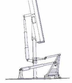 |
Figure 6 presents the extreme positions of the panel, corresponding to loading cases: a — for a = 67°, summer solstice at noon; b — for a = 9°, winter solstice at sunrise.
Fig. 6. Extreme positions
In order to optimize a tank-in-tank system, simulations have been carried out with different DHW profiles and space heating loads. For tank-in-tank systems, the height and diameter of the inside tank might play an important role in the tank design. Therefore, in the current study, the effect of height and diameter of the upper and lower part of the inside tank is investigated by means of 7 different tank-intank designs. Model 1-4 has the same DHW tank volume of 120 litre. In Model 2 and 4, the upper part of the inside tank is located at the same height above the level where the outlet to the auxiliary boiler (middle of the tank) is located. But in Model 1 and 3, the upper part of the inside tank is located at the same level as the inlet of the auxiliary boiler. Model 1 and 2 has larger diameter than Model 3 and 4 in the upper part but smaller diameter at the bottom. In Model 5, 6 and 7, the DHW tank volume is increased to 160 litre and have the same diameter. In Model 5, the upper DHW volume of the inside tank is located above the outlet to the auxiliary boiler, in Model 6, it is located at the same level as the outlet to the auxiliary boiler and in Model 7, it is located below the outlet to the auxiliary boiler.
 |
 |
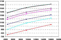
Fig. 5 shows the net utilized solar energy versus the space heating load for 6 m2 solar collector area and different tank-in-tank designs with the Task 26 domestic hot water profile. The net utilized solar energy is the space heating demand + the domestic hot water consumption — the auxiliary energy supply to the top of the heat storage tank. It can be seen that Model 7 has the highest thermal performance compared to the other models followed by Model 6, 5, 2, 1, 4 and 3 respectively. That is: The lower the set point temperature, the higher the thermal performance. It is also seen that the thermal performance of the system is increasing for increasing the space heating demand. With the Task 26 domestic hot water profile, the thermal performance is increasing for increasing auxiliary volume of the hot water tank.
Fig.5. Net utilized solar energy versus space heating load for different tank-in-tank designs with Task 26 DHW
profile
The same tank-in-tank systems are also investigated with the different DHW profiles: High, medium and low flow rates as shown in Fig. 4. Fig. 6 shows the net utilized solar energy versus the space heating load for the seven different models and the high flow rate DHW profile. Model 4 has the highest thermal performance compared to the other models. After model 4 follows Model 1, 6, 5, 7, 3 and 2. The thermal performance of the systems are increasing for increasing space heating load and that the thermal performances of the systems are much higher with the same average daily hot water consumption than with the Task 26 profile. This is caused by the high required set point temperature for the Task 26 profile, in turn due to the fact that the flow rate is even higher than in the high flow
DHW profile and that two discharges can follow one another with short or no interval. For both low and medium flow rate DHW profile, the trend of the net utilized solar energy for the different models is the same. The difference of thermal performance between the best and worst model is about 2-3%.
![image119 Подпись: High flow rate DHW profile 6000 8000 10000 12000 14000 16000 18000 Space heating load [kWh/year]](/img/1155/image119_0.gif) |
||
The differences of the thermal performances caused by the three different DHW profiles are small.
Fig. 6. Net utilized solar energy versus space heating demand for different tank-in-tank designs with high flow
DHW profile
Transient shading of the outer module (left module in Fig. 1) by the edge of the roof or wall starts in the morning earlier at the solar angle — mE <-mF. Correspondingly, it expires later in the evening. Duration of the transient screening in angle units corresponds to Eq. (5), while we exchange the distance between the modules to the distance from the edge of the basis DR^DC. The module is completely illuminated, when the sun reaches the position described by the clock angle mF, while the sun shines along the virtual envelope plane.
An outer module performs close to the stand-alone module once per day, while it performs like an inner module for the second time. Duration of the transient screening of the outer module in Fig. 6 is less than such for the inner one.
 |
 |
Available minimum value of the distance DC min=WC (cos%)/2, when the edges of the basis and the module touch. In this case =x and there is no transient shading effect. If a module should be installed at an infinitive long distance from the edge of the fa$ade, then DC and the duration of the transient screening aspires to zero.
 |
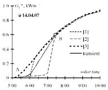
A “PV-module” is modeled with two pyranometers, installed on the outer (“1” & “4”) and inner edges (“2” & “5”) of a plywood sheet (Fig. 7). We use two of such “modules” instead of rotating and commutate the outputs at the moment of “rotating”. Neighboring modules, which screen the beam component of radiation, are the pure plywood sheets installed at a certain distance and with the corresponding deflection angle. Pyranometers “3” and “6” are installed above the “farm” and perform like a stand-alone module with a two-positional tracking. They are used for the experimental control of the limited gain. Figure 7 shows a “farm” with the vertical position, but the same was used to control the “farm” with the tilted (p0=45°) position. The diagram in Fig. 8 shows a recorded transient shading process in the sunny morning on 14 April 2007. The dashed lines are irradiances measured by pyranometers 1, 2 and 3, correspondingly. Lines have finite slopes due to the finite area (25 cm2) of the used pyranometers. The points highlighted correspond to the start of transient screening (point A) and its finish (point B).
 |
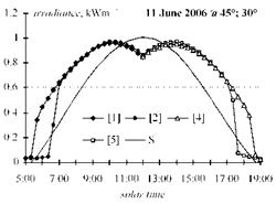 |
The diagram in Fig. 9 shows the recorded irradiance for an inner module exposed with the two — positional tracking while the deflection angle is x =30°. the tilted p0 =45° “farm” was installed due south y0=0 using the relative distance dR = 2. Positions of sensors correspond to Fig. 7. The line without marks shows the irradiance for the stand-alone fixed module at p0 = 45° due south.
Fig. 8. Measured transient shading process for Fig. 9. Recorded irradiance for the module with two-
the stand-alone [3] and the inner module of the positional tracking inside a “farm” while deflection
“farm” [1, 2]. angle is 30° and relative distance dR =2.
A weather data, which generates auxiliary energy results that are closely 365/12 times smaller than the annual one, has to be selected.
In contrast to this previous test method, the days of the core phase are chosen with different criteria. They are chosen in an iterative process where the predicted simulation results of the monthly average values of the internal storage energy and the space heating demand are compared to their corresponding annual values.
Two combisystem simulations are necessary for the development of the test sequence weather data. These are an annual system simulation and a 12-day system simulation. These simulations are carried out using TRNSYS [7]. All system parameters, depending on the annual cycle, have to be
 |
adapted to a shorter 12-day simulation cycle. Furthermore, domestic hot water draw-offs and the space heating demand should have realistic values in comparison to the annual one.
Comparison of annual and
predicted performance
Fig. 1. Iterative process used.
Afterwards, a prediction calculation is necessary in order to be able to make a comparison between annual and test sequence simulation. This comparison should show a good agreement in the space heating demand, the domestic hot water demand, the mean internal storage energy, the solar usable energy and the fractional solar consumption. A methodology for choosing the days is done with an optimization process written in Matlab [8]. It is based on an algorithm that searches the best days out of an annual reference weather file with regard to the defined quality criteria.
Two small low flow SDHW systems based on mantle tanks were tested side-by-side in a laboratory test facility for SDHW systems at the Technical University of Denmark. The systems are identical with exception of the solar collector loops and the circulation pumps. The most important data for the systems are shown in table 1.
One of the systems is equipped with a low flow SOLAR 15-65 pump and a so-called “lifeline” solar collector loop based on a %” copper pipe for the hot solar collector fluid pumped from the solar collector to the mantle tank and on a 5/16” copper pipe for the cold solar collector fluid pumped from the mantle tank to the solar collector. Both the hot and the cold pipes are insulated with glass fibre and enclosed by a PVC jacket with a diameter of 38 mm, see figure 2. The length of the lifeline in the tested system is 16 m. The other system is equipped with a normal circulation pump for solar heating systems, SOLAR 15-40, and a solar collector loop consisting of 33 m 10/8 mm copper pipes insulated with 9 mm INSUL-TUBE insulation.
The thermal characteristics of the lifeline have been investigated [2]. The heat loss coefficients of the hot and the cold pipes of the lifeline depend on the temperature difference between the hot and cold pipe and the temperature difference between the hot pipe and the ambient air temperature. For the hot pipe a typical heat loss coefficient is 0.1 W/K per m, while the heat loss coefficient of the cold pipe is typically placed in the interval from -0.4 to 0.2 W/K per m pipe. That is: In periods
|
Solar collector manufacturer |
Arcon Solvarme A/S |
|
Solar collector type |
ST-NA |
|
Solar collector area |
2.51 m2 |
|
Maximum collector efficiency |
0.801 |
|
Collector heat loss coefficients |
3,21 W/m2K and 0.013 W/m2K |
|
Incidence angle modifier for collector |
3.6 (tangent equation) |
|
Collector orientation |
South facing |
|
Collector tilt |
45° |
|
Mantle tank manufacturer |
Nilan A/S |
|
Mantle tank type |
Danlager 1000 |
|
Domestic hot water volume |
189 l |
|
Auxiliary volume |
86 l |
|
Power of electric heating element heating the auxiliary volume to 51°C |
1000 W |
|
Outer diameter of hot water tank |
0.492 m |
|
Height/diameter ratio of hot water tank |
2.1 |
|
Mantle gap |
0.0115 m |
|
Mantle height |
0.395 m |
|
Heat transfer area, mantle |
0.61 m2 |
|
Water volume above upper mantle level |
97 l |
|
Mantle inlet |
Top of mantle |
|
Thickness of hot water tank wall |
0.0030 m |
|
Thickness of mantle wall |
0.0025 m |
|
Solar collector fluid |
40% propylene glycol/water mixture |
|
Location |
Technical University of Denmark, Kgs. Lyngby, Denmark. Latitude: 56°N |
|
The mantle tanks are built into a 60 x 60 x 181 cm cabinet. T |
he space between the tank and the |
|
cabinet is filled up with PUR foam insulation. The volume flow rates in the solar collector loops are about 0.5 l/min. |
 |
|
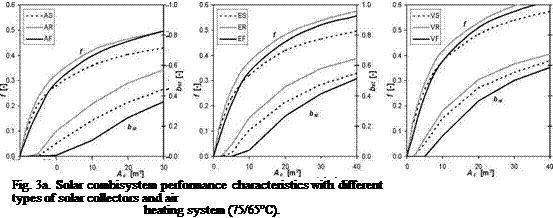
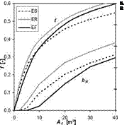
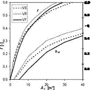
Computer simulation analyses for solar combisystems with solar collectors with different rate of evacuation, different types of collector-building integration and different types of heating systems have been performed and several result sets have been obtained. Fig. 3a-c show the performance characteristics of investigated solar combisystem configurations (heating systems, flat-plate collectors, type of installation) expressed by means of system solar fraction f and specific stagnation time bst dependent on collector area Ac as variable parameter.
Fig. 3b. Solar combisystem performance characteristics with different types of solar collectors and radiators
 |
 |
|
 |
||
for space heating (55/45°C).
Fig. 3c. Solar combisystem performance characteristics with different types of solar collectors and floor
heating (35/25°C).
As illustrated in figures 3a to 3c the performance of the solar combisystem (solar fraction) generally increases with the decrease in operation temperature for the space heating system and higher degree of solar collector evacuation due higher efficiency. On the other side, increase in solar fraction by enlargement of the collector area of its efficiency is always coupled with increase in stagnation time. Direct integration of solar collectors into the roof (thermally coupled without air gap) when compared with facade collectors results in higher solar fraction but leads also to considerably higher stagnation levels and specific stagnation time due to an unutilisable summer irradiation peak. General comparison of the separate installation of solar collectors on the roof or formal roof integration (with ventilated air gap as major type of roof integration) with facade direct integration leads to a different situation. For most of the investigated configurations the facade solar collectors result in lower or equal collector area needed compared to separate roof installation, especially when solar fraction above 30 % is required. At the same time, considerably lower stagnation times are achieved for faqade collectors.
Fig. 4 shows the change of solar fraction Af [%] for usual combisystem collector area of 10 m2 for investigated configurations related to reference case (atmospheric collector, separate installation, 55/45 °C with fAS55 = 28 %). Integration of all investigated solar collector types into the roof and integration of atmospheric and evacuated solar collectors into the faqade results in higher solar fraction of solar combisystems, especially above > 8 m2 of collector area (in the graph 10 m2). Additionally, the diagram shows the influence on solar fraction of different supply temperatures for heating of the building. As previously mentioned in general, lower supply temperature leads to higher performance of the solar combisystems, e. g. using 10 m2 separate installed atmospheric flat — plate collector combined with a low-temperature radiant heating system (35/25 °C) leads to an increase of solar fraction by 3 % (/As, 35 = 31 %) compared to reference system. Contrary, higher operation temperatures e. g. for air heating system (75/65 °C) decreases the solar fraction by 3 % (/As, 75 = 25 %).
Fig. 4. Change of solar fraction for collector area (Ac = 10 m2) based on reference case (/As, 55 = 28 %).