Как выбрать гостиницу для кошек
14 декабря, 2021
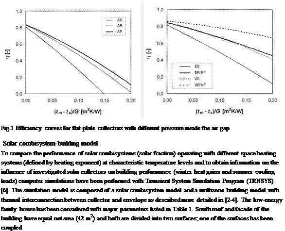
The analysis considers three types of solar collectors with different levels of pressure inside the front air gap to affect the front heat loss coefficient. Fig.1 shows the efficiency curves for idealized solar flat-plate collectors with ambient pressure (A-atmospheric collector, 100 kPa), reduced pressure (E-evacuated collector, 1 kPa) and vacuum (V-vacuum collector, 0.1 Pa, only theoretical case) obtained from mathematical model KOLEKTOR 2.2 [5]. Moreover, each variant is evaluated with three types of collector-envelope configuration (S-separate installation, R-roof integration, F — faqade integration). The thermal resistance of the envelope has been considered 6 m2K/W (low — energy house). Efficiency curves for roof and facade integration differ in the case of atmospheric collectors due to convection heat transfer reduction with higher slope of air gap in contrast to evacuated and vacuum collectors which have the convection heat transfer in the air gap completely eliminated. Further information on evacuated collector efficiency can be found in previous research

[4].
to the collector absorber (absorber temperature is identical with temperature of outer insulation layer). Splitting the envelope (roof, facade) into two surfaces allows varying the solar collector area Ac to envelope area Ae ratio (coverage factor) for parametric analysis.
Table 1. Major parameters of solar combisystem and building model.
|
Heated floor area / building volume |
150 m2 / 550 m3 |
|
Envelope U-value |
6 m2.K/W |
|
Ventilation with heat recovery |
0,3 ACH, efficiency 75 % |
|
Space heating demand Qsh |
6880 kWh/a ~ 45 kWh/m2a |
|
Space cooling demand Qsc |
2 kWh/a |
|
Storage tank volume VS |
1200 l |
|
Solar collector area Ac |
variable (1…42 m2) |
|
Average DHW demand Qdhw |
200 l/day (55/12 °C) ~ 3710 kWh/a |
|
Space heating system variants |
75/65 °C; n = 1.5 (air heating) 55/45 °C; n = 1.3 (radiators) 35/25 °C; n = 1.1 (radiant heating) |
 |
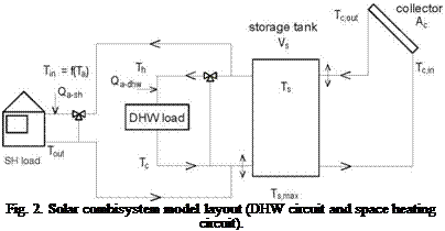
The solar combisystem model is based on compact integrated central heat storage tank (1200 l) with ideal stratification (variable inlets) with two heating circuits (DHW and space heating). Two auxiliary heaters were applied, first to output for DHW load (Qa-dhw) and second for space heating (Qa-sh). The combisystem model consists of idealized elements (no heat losses, no heat exchangers) to perform simulations strictly focused on energy flows and the interaction between the collector, storage tank and building environment. The schematic diagram of the solar combisystem model is shown in Fig.2.
For analysis, three different types of heating systems (air heating, radiators, radiant heating) have been considered with typical nominal operation temperatures (75/65 °C, 55/45 °C, 35/25 °C) and relevant heating exponents (n = 1.5, n = 1.3, n = 1.1). Supply temperature control according to the ambient temperature is provided. An overview of the major parameters of solar combisystem model is given in Table 1.
Principal observed parameters for the building performance were winter heat gains Aqsh and summer cooling loads Aqsc induced by collectors integrated into the envelope. For the solar system performance, solar fraction f and specific stagnation time bst have been evaluated.