Как выбрать гостиницу для кошек
14 декабря, 2021
For the simulations daily and weekly load variations for the DHW with hourly resolution were created in order to separate between the ambient temperature dependant SH and independently varying DHW loads. To achieve realistic load profiles, they were created based on measurements from operational plants.
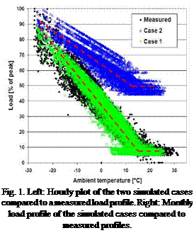
Measured hourly load data was obtained from six plants of various sizes. Measured monthly total loads were obtained from 18 plants of various sizes. It was found that the studied load profiles are basically of the same shape, i. e. mostly SH with a comparatively small summer loads (DHW and partly or mostly distribution losses), lower than 15% of peak load.
1.2. Load profiles for simulation studies
Based on the measured data representative generic load profiles were created. The DHW profile was created based on data when the SH is off or small. As the measured data included only the ambient temperature, no simulations regarding solar irradiation can be made for the same data set. Thus the SH load profile was created by matching visually the simulated to approximate the measured load characteristics while keeping the same peak load and approximate yearly total load. Case 1 represents the majority of the plants. As in the studied plant portfolio all cases except one had low summer load, a
 |
 |
fictive high summer load Case 2 was created by simply scaling up the DHW consumption of Case 1 and reducing the SH load keeping the same peak power. The studied climate data was TMY2 for Jokioinen (Finland), latitude 60.8°.
SHW win was chosen as simulation tool because of ready and tested system models and it has also been used in a similar project earlier by TUG in Austria [1]. Yearly simulations were done with a subhourly resolution.
 |
The simulation study is based on a single family house with a living area of 128 m2 located in Wurzburg, Germany. The roof area where the collectors are mounted is facing south with an inclination of 45o. The space heating demand of the building conforms to the current legal energy saving regulations (EnEV) and amounts to 71 kWh/ (m2 a) respectively 9090 kWh/a. The heating control is automatically adjusted to the outside temperature with a maximum flow/return temperature of 35/25°C. The heat demand for hot water amounts to 2945 kWh/a for a daily use of 200 litres at 45°C. The total heat demand (thermal requirement) for hot water preparation and space heating amounts to 12680 kWh/a, assuming heat losses of a conventional hot water store of 645 kWh/a. The flow temperatures for the brine were calculated based on measurements taken at a heat pump system using a borehole heat exchanger and range from 7°C in February to 20°C in July. The heat pump used in system A shows a COP (Coefficient of Performance) of 4,3 according to EN 14511 at 5K temperature difference. In system B a store-integrated heat pump is used which has a different thermal behaviour due to its positioning. This heat pump features a COP as per EN 14511 of 4,1 at 5 K temperature difference. The same flat plate collector with a total aperture area of 12 m2 and performance parameters of a “good” flat plate collector was used for both systems.
Table 1 shows the most important results of the annual simulations carried out for the two systems A and B. In addition the thermal behaviour of a pure heat pump system without solar collectors (system C) was simulated for comparison. This system uses a similar combistore as system A, however with a smaller volume of only 400 litres. For all systems the electric energy consumption for the hydraulic pumps was not taken into consideration for reasons of simplification.
|
Table 1: Results of annual system simulation
|
Table 1 shows that system B requires the lowest amount of heat delivered by the heat pump in order to cover the entire heat demand for hot water preparing and space heating. Furthermore, this system provides the highest “usable hot water volume” and therefore offers the greatest hot water comfort. The positive thermal behaviour of system B is due to the efficient technology for hot water preparation (external heat exchanger combined with a controlled pump) and to the fact that at this system the highest solar energy gains are delivered to the combistore (3685 kWh). Moreover, the combistore of system B shows less heat loss than the combistore of system A. In system A the heat delivered from the collectors to the combistore is lower than in system B due to the control strategy of the collector loop pump: Within regular waiting periods during charging the buffer store it is checked if it is possible to charge the combistore. Nevertheless, system A requires the least electric energy consumption of the heat pump. That is because system A shows the highest COP due to the high temperature level in the buffer store which can occasionally be used as heat source for the heat pump. In comparison to system C (without solar thermal contribution) system A requires approx. 1000 kWh less electricity in order to operate the heat pump. The annual COP increases from 4,0 to 4,4 due to the solar thermal system. As can be expected, system A shows a high collector energy gain due to the additional buffer store.
The investigations have shown that the combination of a solar combisystem with a heat pump is a promising approach for saving primary energy. Due to the use of an additional buffer store in system A the electric energy consumption is less than in system B despite the higher delivered heat of the heat pump. This is due to the higher seasonal performance factor of the heat pump in system A. An
additional saving potential in system B can be utilised if the solar circuit is coupled with the brine circuit by a heat exchanger in order to preheat the return flow of the brine.
In order to compare different combinations of solar thermal systems and heat pumps in an objective way it is essential that standardised test — and evaluation procedures become available.
References:
[1] Kuhl, L., Wendker, K., Fisch, N.: Praxistest von solarunterstutzten Warmepumpen-Heizsystemen; Tagungsband zum 17 Symposium Thermische Solarenergie, Otti-Technologie-Kolleg, Regensburg, Mai 2007; (2) ENV 12977-2: 2001: Thermal solar systems and components — Custom built systems — Part 2: Test Methods, ISBN 0-580-37754-7
[2] EN 14511-3: Air conditioners, liquid chilling packages and heat pumps with electrically driven compressors for space heating and cooling — Part 3: Test methods
A. Troi[9]*, Y. Vougiouklakis2, E. Korma2, D. Jahnig3, E. Wiemken4, G. Franchini5, D.
Mugnier6, B. Egilegor7, P. Melograno1, W. Sparber1
1 EURAC, Institute for Renewable Energy, Viale Druso, 1, 39100 Bolzano, Italy
2 CRES, Centre for Renewable Energy Systems, 19th km Marathonos Ave.,190 09 Pikermi, Greece
3 AEE INTEC, Institute for Sustainable Technolgies, Feldgasse 19, 8200 Gleisdorf, Austria
4 Fraunhofer Institut fur Solare Energiesysteme (ISE), Heidenhofstrahe 2, 79110 Freiburg, Germany
5 Universita degli studi di Bergamo, viale Marconi, 5, 24044 Dalmine (BG), Italy
6 TECSOL, 105 rue Alfred Kastler, 66000 Perpignan, France
7 Ikerlan Technological Research Centre, Juan de la Cierva, 1, 01510 Minano (Alava), Spain
* Corresponding Author, alexandra. troi@eurac. edu
In autumn 2007 the European project SolarCombi+ has been started. The aim of this project is to take newly commercially available small scale sorption chillers and identify and promote standardised Solar Combi+ systems for small applications: i. e. combined solar water and space heating and cooling up to a cooling load of 20 kW. A thorough market study at project start outlined the possible markets — both in the sense of applications and countries of major interest — and described promising consumer attitudes: 40% of them are even willing to pay more for a product if it is energy efficient — Solar Combi+ systems can have a significant market if they are as reliable and convenient as conventional air conditioning systems even if they are somewhat more expensive. A large number of Virtual Case studies will now be performed in order to identify a standard system configurations, which work best under different conditions. Accelerating and smoothing the market entry of small scale Solar Combi+, the project will contribute to achieving energy policy goals of the EU. Keywords: solar cooling, small scale sorption chillers, market analysis, standard systems
The combined use of solar energy for heating and cooling has the potential to upgrade solar thermal energy from mainly DHW provider to a major building energy supplier [1, 2] The hereto necessary sorption chillers, however, used to be available mainly in higher power range [3], but now several new small scale sorption chillers are being offered. They will open the market for small cooling applications, which make up for the major part of heating and a constantly growing part of cooling demand in Europe.
Aim of the here presented IEE1 funded project “Solar Combi+” is to take these newly commercially available small scale sorption chillers and identify and promote standardised Solar Combi+ systems for small applications (residential, catering, small commercial and office buildings, up to a cooling demand of 20kW).
Now is the right moment to support the market entry of Solar Combi+ with reliable dimensioning and a comprehensive analysis of promising applications. In this way the spread of Solar Combi+ can go hand in hand with the build up of important solar thermal markets for e. g. Spain, France and Italy [4]. One has also to regard, that cooling applications are state of the art in office and commercial buildings not only in southern countries but all over Europe, and comfort requirements in residential sector is constantly growing.
The participation of all European producers of small scale solar driven sorption chillers as direct partners as well as the declaration of interest of the solar thermal industry, shows the importance of the project for a smooth and sustainable market entry of Solar Combi+ systems.
This paper should give an overview on the rationale behind the project, its goals and its approach, as well as present the market situation: After describing with more detail the addressed barriers and offered solution, the technology is briefly summarised, the work plan of the project is presented and first results of the market analysis are discussed. The paper closes with an outlook on upcoming results and the impact which is expected from the project.
Fig.4 shows the hydraulic schemes of the old and the new heating system with the heat meters which are red marked and named “Fdxx” and listed in Table 1.
to 10th October, Lisbon — Portugal *
|
Old heating system: |
New solar combisystem: |
|
— |
Fd1: “Solar Gain” |
|
— |
Fd2: “Boiler” |
|
Fd15: “Domestic Hot Water-Heating” |
— |
|
Fd16: “Space Heating” |
Fd3: “Space Heating” |
|
Fd18: “Domestic Hot Water-Circulation” |
Fd5: “Domestic Hot Water-Circulation” |
|
Fd19: “Domestic Hot Water-Consumption” |
Fd4: “Domestic Hot Water-Consumption” |
|
Gas meter: “Natural Gas Consumption” |
Gas meter: “Natural Gas Consumption” |
|
Electricity meter: “Electricity Consumption” |
Electricity meter: “Electricity Consumption” |
|
Tc5 ~^ Collector —< Tc19 |
|
Table 1. List of energy meters in the old and the new heating system of the demonstration house. |
In Table 2 the main measurement results of the two monitoring periods (without solar heating system in 2005 and with solar heating system in 2006/07) are presented. Solar gain of the collectors for one year is 2500 kWh or 370 kWh per m2 respectively. The solar fraction is SF=13.5%. The calculation of the fractional energy savings according to the definitions within IEA SHC Task 26 results in fsav, therm = 20% against the Task26 reference system. The FSC (Fractional Solar Consumption) can only be estimated based on weather data in Copenhagen resulting in about FSC = 0.25.
Space heating consumption (SH) in the second monitoring period is about 20% less compared to the first monitoring period. This fits quite well to the reduction of the heating degree days by 17% (3097 HDD to 2578 HDD) even though two additional rooms in the basement were heated in the second period.
After an intensive teaching process to the occupants of the house, how to use the thermostat valves at the radiators correctly, the measurements showed a quite big change: the temperature difference in the space heating loop increased significantly from 7.7 to 12 Kelvin on average. The occupants also reported that the indoor
|
Table 2. Monthly monitoring data and key numbers for one year periods for the old conventional heating system and the new solar combisystem.
|
Due to the much more constant room temperatures the occupants stopped to open and close the windows for controlling the room temperature. This behaviour typically increases the space heating consumption significantly and therefore it can be assumed that this change of behaviour most likely is the reason why the total space heating consumption followed the heating degree days, even though two more rooms were heated.
Domestic hot water consumption (DHW) decreased significantly by 20% from 9.0 to 7.2 kWh/day. The main reason for that might be the lower set temperature of 50°C instead of 70°C in the old system (due to the small 50 litre hot water tank) and the higher resistance of the flat plate heat exchanger which reduced the maximum flow rate.
A huge difference could be observed at domestic hot water circulation heat losses. In the old system the circulation pump was operating daily from 6 to 10 and 17 to 20 resulting in 297 kWh heat losses just within one month. This was more than the hot water consumption itself during most of the months. Therefore, the occupants switched off again the circulation pump at the end of the first monitoring period.
In the new solar combisystem a new control strategy was introduced, the so called “circulation on demand” (see Fig. 5) [6]. A
![]() pump. After about 15 to 20 seconds hot water reaches the tap without wasting water and for example the shower can start with hot water at the tap immediately. Using this strategy the circulation heat losses reduced dramatically to 169 kWh within a full year, this is only about 7% of the domestic hot water consumption.
pump. After about 15 to 20 seconds hot water reaches the tap without wasting water and for example the shower can start with hot water at the tap immediately. Using this strategy the circulation heat losses reduced dramatically to 169 kWh within a full year, this is only about 7% of the domestic hot water consumption.
|
The electricity consumption of the total heating system during the heating season Nov 05 to April 06 is constant at about 3.3 to 3.4 kWh/day. The electricity consumption of the new solar combisystem in the same period was somehow lower even though that some more pumps and valves are installed and in operation. A main advantage in the solar combisystem might be that the main pump for space heating and hot water preparation is speed controlled and therefore operating quite efficient.
The last four columns in Table 2 present some calculated key numbers for both systems.
The boiler efficiency (eta_boil) shows clearly the difference between the old non-condensing and the new condensing natural gas boiler. In summertime with very low heat load the efficiency decreases significantly in both cases down to 80%. Nevertheless the old boiler shows surprisingly high efficiency in spring and autumn. An explanation for that could be, that in December 2004 of this old boiler had to be repaired including the change of the internal heat exchanger.
The hydraulic efficiency (eta_hyd) is defined as the heat demand (DHW and SH) divided by heat production (solar gain and boiler output). In this case heat losses of domestic hot water circulation are calculated as system losses and not as demand (see Table 2). Comparing the two hydraulic schemes in Fig. 4 shows clearly, that a solar combisystem consists of more hydraulic components, internal piping and last but not least a much bigger heat store (in this case 360 litres compared to 50 litres) leading to higher heat losses due to larger surface. These higher heat losses typically are compensated by solar energy in summertime, but may lead to decreased performance of the complete system in winter time. Therefore, all measures to reduce heat losses (good insulation of tank and hydraulic components, short internal piping, etc.) are essential for high overall performance.
Comparison of the monitoring results in the period January to March shows a difference of the hydraulic efficiency of 3%-points (97% to 94%) even though the old system has no hot water circulation in operation but the new solar combisystem has. In November and December 2005 the huge influence of the hot water circulation losses in the old system is clear to see. The new solar combisystem in total reached a hydraulic efficiency including hot water circulation losses of 92%, which is quite a high value.
The real difference can be observed when looking at the utilization factor COP (hot water and space heating consumption in relation to gas consumption) which combines the boiler efficiency (eta_boil) and the hydraulic efficiency (eta_hyd) of the heating system, which includes heat losses of the heat storage and all the pipes and components inside the technical unit as well. In the old system in July 2005 only 59% of the consumed energy of natural gas finally was used as hot water, 41% are losses. This inefficiency of conventional hot water preparation is also the reason why the energy savings of solar heating systems in summertime are much higher in comparison to the heat load [7].
The solar combisystem reaches much higher COP values mainly due to two reasons: the boiler efficiency (eta_boil) of the new condensing natural gas boiler is on average about 6%-points higher compared to the old non-condensing natural gas boiler and of course the gained solar energy is counting as non-fossil heat input and therefore calculated for “free”.
Within this project it was possible to measure the heat flows in the same building before and after the installation of a solar combisystem. Therefore the energy savings can be calculated based on measurements and not based on assumptions for the case of the old heating system.
Based on the investigated natural gas utilization (COP) and the measured heat load of the old heating system a characteristic COP-curve can be generated. The theoretical natural gas consumption during the second monitoring period can be interpolated with this COP-curve and the new measured heat load.
Table 3 presents the calculated energy savings of this demonstration house. The total natural gas savings are equal to 3615 kWh or 18% respectively. In relation to the collector area of 6.75 m2 the energy savings are 536 kWh/m2, where the solar gain is 370 kWh/m2.
|
Table 3. Calculated energy savings of the new heating system compared to the old one.
|
A new hydraulic and control concept for a solar combisystem was developed. A prototype for the laboratory was built and tested, and finally a demonstration system was installed and measured in practice. The main goal was to develop a concept in combination with a standard condensing natural gas boiler, which leads to an overall coefficient of performance as high as possible. Based on the fact that such condensing natural gas boilers are powerful enough for direct hot water preparation, the newly developed concept avoids heating up the auxiliary volume to high temperatures, which is normally done just to have a buffer for hot water preparation. The new strategy leads to a lower average temperature in the solar tank, and more importantly, in the piping within the system, which further on significantly reduces the system heat losses. The major problem, which had to be solved, was to ensure hot water preparation with constant tap temperature during the always changing operating conditions.
Long term monitoring results in a demonstration one family house showed after 20 month of operation that the system works in a stable and reliable way. The results showed high performance thanks to low system heat losses and comparable high boiler efficiency. Due to the system concept, also significant reductions on the heat demand side could be realized: 20% less domestic hot water consumption, 93% less hot water circulation losses based on hot water consumption and slightly less space heating consumption even though two more rooms were heated in the demonstration house.
[1] Furbo, S., et. al. (2007), „Competitive solar heating systems for residential buildings”, Final Report, Department of Civil Engineering — Technical University of Denmark, Kgs. Lyngby, Denmark, http://www. physics. uio. no/energy/rebus/downloads/REBUS_final_01-2007.pdf
[2] Thur A., Furbo S., Fiedler F., Bales C., “Development of a compact solar combisystem”, Proceedings EuroSun 2006 Congress, Glasgow, Scotland, 2006
[3] S. Furbo, J. M. Schultz & A. Thur (2007). Energy savings for a solar heating system in practice. ISES Solar World Congress Proceedings, Beijing, China.
[4] A. Thur, Compact Solar Combisystem — High Efficiency by Minimizing Temperature, PhD-Thesis, Rapport R-160, Department of Civil Engineering, Technical University of Denmark, 2007; www. aee- intec. at/0uploads/dateien437.pdf
[5] F. Fiedler, Combined Solar and Pellet Heating Systems — Studies of Energy Use and CO-Emissions, Doctoral Dissertation, Malerdalen University, Vasteras, Sweden, 2006
[6] J. Apel, Vergleich von Zirkulationsstrategien fur den Trinkwasserkreislauf in einem Solarkombisystem, Diplomarbeit, Fachhochschule fur Technik und Wirtschaft, Berlin, 2005
[7] A. Thur, L. J. Shah & S. Furbo (2006). Energy savings for solar heating systems. Solar Energy Vol. 80, Issue 11, pp. 1463-1474.
The current study is an extension to the previous experimental study, however, the objective of the current study is to determine how the heat pump unit responds to a wide range of input temperatures. As well, a goal of the current study is to determine if the steady-state model previously developed in the first study can accurately predict the dynamic operation of the system. A varying power input to the heaters was applied ranging from 750 — 1500 W in a sinusoidal fashion, similar to that of a daily solar heat input. The fluid temperatures delivered to the evaporator varied between 15 and 37oC corresponding to the power output of the heaters. The results of the current study are compared to the simulated results of Freeman’s model, and will be used to eventually refine the model to better predict the actual operation of an ISAHP system.
 |
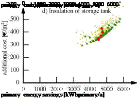 |
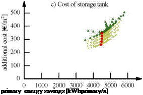
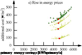
A closer look on the results of dimensioning the base case leads to a comprehensive knowledge about the MaxLean system behaviour and the advantages of the concept. To gain insight into the influence the components have on the optimised system, a number of parameter variations were performed. For each variation a new optimisation procedure was carried out leading to different curves in the cost/savings diagram. Figure 3 gives an overview of the parameters varied and the results of the optimisation runs.
 variation
* base case
• best points
Fig. 3. Cost benefit diagrams of the parameter variations. The triangular dots in the respective charts
represent the dimensioning of the base case. The circular dots are the associated best points, generated with
the varied parameters. a) Cost of solar collector: 100 % to 70 % of the initial price. b) Efficiency curve of
solar collector: , From a low efficiency to a high efficiency flat plate collector. c) Cost of storage tank: 100 %
to 60 % of the initial price. d) Insulation of storage tank: 7.5 cm to 17.5 cm. e) Variation of the rise in energy
prices. 1.3 %/a to 7.5 %/a.
— Portugal *
|
Variation |
cost/benefit ratio [€/kWhprlmary] |
additional cost [€/a] |
primary energy savings [kWhpnmary/a] |
V store [m3] |
Acollecotr [m2] |
||
|
Base Case |
0.077 |
347 |
4502 |
0.67 |
8.9 |
||
|
95 |
0.075 |
340 |
4552 |
0.67 |
9.2 |
||
|
cost of solar |
90 |
0.072 |
328 |
4552 |
0.67 |
9.2 |
|
|
/£ / |
collector |
85 |
0.069 |
322 |
4653 |
0.65 |
10 |
|
/ € |
[% of initial |
80 |
0.067 |
325 |
4863 |
0.69 |
11 |
|
cost] |
75 |
0.064 |
312 |
4876 |
0.67 |
11.3 |
|
|
70 |
0.061 |
307 |
5032 |
0.67 |
12.4 |
|
Table 1. Results of the optimised systems generated by dimensioning the MaxLean system with varying parameters. |
|
95 |
0.075 |
336 |
4502 |
0.67 |
8.9 |
||||
|
90 |
0.072 |
326 |
4502 |
0.67 |
8.9 |
||||
|
cost of |
85 |
0.07 |
316 |
4502 |
0.67 |
8.9 |
|||
|
€ |
storage tank |
80 |
0.068 |
306 |
4502 |
0.67 |
8.9 |
||
|
V/ |
[% of |
75 |
0.066 |
295 |
4502 |
0.67 |
8.9 |
||
|
initial cost] |
70 |
0.063 |
283 |
4476 |
0.67 |
8.8 |
|||
|
65 |
0.061 |
270 |
4444 |
0.71 |
8.4 |
||||
|
60 |
0.058 |
260 |
4444 |
0.71 |
8.4 |
||||
|
0.075 |
0.091 |
428 |
4701 |
0.77 |
12 |
||||
|
0 |
f |
insulation of |
|||||||
|
a |
0.1 |
0.084 |
398 |
4743 |
0.75 |
11 |
|||
|
| |
storage tank |
||||||||
|
n |
0.125 |
0.08 |
371 |
4639 |
0.69 |
10.1 |
|||
|
[m] |
0.175 |
0.075 |
339 |
4517 |
0.65 |
8.8 |
|||
|
rise in |
3 |
0.066 |
296 |
4502 |
0.67 |
8.9 |
|||
|
£ |
energy prices |
5 |
0.049 |
218 |
4479 |
0.65 |
9 |
||
|
—J |
[%/a] |
7.5 |
0.02 |
93 |
4594 |
0.67 |
9.5 |
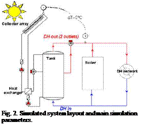
There are several possible ways to connect a solar thermal plant to a DH network, with no proven general optimal system layout. The chosen system design principle is shown in fig 2., where the storage tank is connected in parallel with boilers. The control system keeps the outlet temperature from the collector array always above the required DH supply temperature by varying the collector loop mass flow rate. This control strategy is needed, if one wants to be able to completely turn off the boilers for a period during summer.
The main sizing criteria was to be able to turn off boiler(s) for some period during the summer, as this would both save maintenance costs and reduce boiler operation at low efficiency. This requires a solar fraction of around 90-95% during June-July. It should be mentioned that this is not the optimal case for the solar thermal plant as high solar fractions result in lower specific collector yields, mostly because of higher collector temperatures and the fact that the storage tank is more often fully charged. It was also decided that for simplicity boiler operation would not be considered in the storage tank sizing. The benefits of having a storage tank available for a boiler are too difficult to convert to economical benefits in a generalized manner, and can only be considered case to case when sizing a plant.
Collector
 По (-) 0.8
a1 (W/m2K) 1.76
a2 (W/m2K2) 0.0323
A total (m2) 13.52
Aaperture (m ) 12 5
Storage tank
h/D ratio (-) 2.5
lave, internal (W/mK) 0.8
Insulation thickness (m) 0.3
DH flow temperatures
Tsupply/Treturn winter (°С) 90/50
Tsuppiy/Treturn summer (°С) 65/40
Tamb at sizing point (°С) -30
The scenario is that solar panel array and heat storage tank are added to an existing DH-plant. The panel array and storage tank are ground mounted. Expected main financial savings: fuel, maintenance and electricity. Cost functions for the investment, running costs and savings were based on earlier studies, reported costs from realized plants and budget prices from manufacturers. The NPV calculations were done and the results presented in a manner that tries to answer the question “Under which scenarios would it be feasible?” rather than more traditional case studies, where the feasibility for only a few scenarios are calculated and for which a sensitivity analysis is done. In the presented graphs a shortest feasible payback period for a scenario is found where the curve crosses the x-axis.
The useful lifetime of a solar thermal plant is estimated to be 20-30 years. No subsidies are considered in the calculations. At the time of the study, energy prices for large scale consumers were as in table 1. The calculated electricity savings were so small that changes in electricity price had insignificant effect on feasibility.
|
Table 1. Used energy prices.
|
It must be noted here that economic viability is up to the investor to decide, keeping in mind that different actors within the heat service business may have different decision criteria depending on company size and long term strategy. Therefore only comments on whether a feasible payback period can be found within the lifetime of the plant are given here.
Mihai Radulescu1* and Aude Lepeltier2
1 EDF R&D Site des Renardieres, Dept EnerBat, Avenue des Renardieres — Ecuelles, 77818 Moret sur Loing
2 Ecole des Mines de Douai, 941 rue Charles Bourseul, BP 10838, 59508 Douai Cedex
* Corresponding author, mihai. radulescu@edf. fr
This paper presents the efficiency improvement and electricity economy obtained by introducing an advanced control of a hot water solar heater (HWSH) using a weather forecast. In order to quantify the energy gain of the advanced control a numerical model was built for the storage tank. This model takes into account all inlet and outlet energy fluxes and it’s able to determine the temperature inside the tank at any moment and height. The advance control is acting on the set-up temperature of the auxiliary electric heater in order to prepare a reduced quantity of hot water during night and to allow to the solar loop to recover as much as solar energy possible. The comparison between a standard system and a HWSH with weather forecast shows that a 7% annual electrical economy is found and a 3% efficiency improvement.
Keywords: solar thermal, hot water, control system, weather forecast.
Electricity production in France is mostly nuclear with 88% completed by small parts of natural gas 4% and hydraulic 8%. The most important electricity producer is by far Electricite de France (EDF) with a total annual capacity of about 650 TWh, and just 490 TWh in France.
Face to global warming and approaching oil peak, research efforts turned toward renewable energy sources. Theses technologies can produce “clean” energy without or with low carbon dioxide emissions but remain still expensive and less widespread. One technology, with unlimited resources and a good potential to overcome the actual setbacks, is the solar thermal. Probably the main disadvantages leading to low solar energy use are the intermittent availability and the low reliability of the energy source. Transforming the solar energy in heat seams so simple, but to recover this heat and to use it efficiently becomes more complicated. Heat has to be carried by a fluid (air or water) to be used immediately or to be stored.
This paper focuses on domestic hot water solar heaters (HWSH) with a storage tank and forced circulation of the heat carrier fluid. Such a system is coupled with a meteorological device (not described) to provide the weather forecast. The energy economy and comfort gain are established with respect to a classical HWSH. The description of the system will be followed by a short explanation of the model. The results are divided in two parts: with and without the weather forecast.
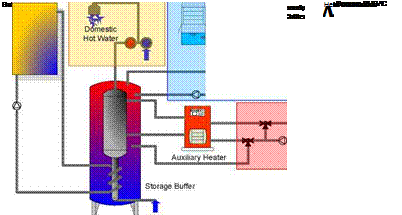 |
Solar Combi+ systems use heat from solar thermal collectors to provide heating in winter, cooling and summer and domestic hot water all the year round. Fig. 1 sketches the main components, which make up a typical system: (i) the solar thermal collector to provide the heat might be backed up by another heat source, (ii) a storage tank can either be installed on the warm side, as drawn in the figure, on the cold side or on both, (iii) the domestic hot water tank might be included in the hot storage or be a separate tank, (iv) the sorption chiller is fed with hot water (70-100°C), (v) rejects heat at intermediate temperature (30-40°C) to a cooling tower (dry, wet) or another heat sink (as e. g. a swimming pool) and (vi) delivers chilled water to the cold distribution (be it a chilled ceiling, fan-coils or air handling units), whereas (vii) the heat distribution should possibly be a low temperature system.
Fig. 1. Example for the system components of a Solar Combi + System and project logo
All the single components of a system are now market available: But there is so far hardly a provider of system solutions, and that’s the point where the project is puts efforts forth.
Jose Cavaco*, Pedro Horta, Joao Farinha Mendes,
INETI, Department of Renewable Energies, Campus do Lumiar do INETI, 1649-038 Lisbon, Portugal
* Corresponding Author, iose. cavaco@ineti. pt
Prior to recent building regulations enforcement, the use of Solar Thermal Systems (STS) in residential buildings was dependent on the proactive role of building promoters, as is the case of EPUL (Public Company of Urbanism of Lisbon), which has studied along the last decade, after a joint work with INETI, the possibility of using solar energy in new apartment buildings.
Such a STS was installed in a new multi-storey building just before the new building
regulations, making the use of solar energy in residential buildings mandatory, was enforced.
At the present, INETI is monitoring the STS over a two year period. The monitoring results, reported in the present article, make this system a good example for demonstration purposes, either from technical solutions and operation points of view, having in mind the need (because of solar obligation) and interest (for building certification) for the adoption of such systems in multi-owned buildings. [13]
According to the agreement between the two entities, INETI also assisted EPUL on choosing the solar thermal system (STS) supplier, on the detailed project approval and on the system monitoring for a period of 2 years, to have an idea of system efficiency in comparison with initial estimations and its follow-up for a period of time considered long enough to be sure about its behaviour in the future, giving also the opportunity to detect problems that can be solved in this initial period.
This paper presents a description of the solar thermal system configuration in point 2, and a description of the implemented monitoring scheme in point 3. The data already obtained will be shown and analyzed in point 4, as well as the actual dwelling owners’ degree of satisfaction. Present conclusions and remarks are presented in point 5.