Как выбрать гостиницу для кошек
14 декабря, 2021
The principle setup of membrane distillation (MD) is based on a hydrophobic, microporous membrane as shown in figure 1. Due to the high surface tension of the polymeric membrane materials, liquid water is retained from entering the pores while molecular water in the vapor phase can pass through.
A hydrophobic membrane is characterized by the fact that the surrounding liquid water can not enter its pores (capillary depression). This effect depends on the relative intensity of cohesiveness between the liquid molecules and the adhesive power between liquid molecules and the membrane material. These forces are responsible for the contact angle © = 180 — © between the liquid surface and the membrane wall. In case of a non wet-able membrane, the contact angle is © > 90° and a convex meniscus as shown on the right hand side of figure 1 is formed. The hydrostatic pressure of the water columns on both sides of the membrane must remain less than the wetting pressure of the membrane in order to restrict liquid water from passing the pores.
Temperature and vapour pressure
profile across the membrane
Evaporator Condenser
channel channel
Fig 1: Principle of direct contact membrane distillation (DCMD)
Membranes for MD usually have a pore diameter of 0.1- 0.4 pm and are made from PTFE, PVDF or PP polymers. The driving force in a MD process is the vapor pressure difference across both
membrane interfaces. For direct contact membrane distillation (DCMD) , this vapor pressure difference arises due to a temperature gradient between a hot feed stream in the evaporator channel and a cooled permeate stream in the permeate channel.
In MD, it is assumed that mass transfer is based on convection and diffusion of water vapor through the microporous membrane. Finally, summarizing the constants of different equations describing the convection and diffusion process in a single transport coefficient C leads to the simplified equation: Nw = C ■ dp
Usually C is determined by experimental investigations and is in the order of 3■ 10-7 to 4■Ю6kg/m2sPa depending on membrane material and geometry.
As can be seen in the graph of figure 2, the pressure difference across the membrane dp is calculated for the temperature differences between the hot and cold membrane interface according
figure 1 AT10 = T1 — T0 from the gradient of vapor pressure curve dP at average temperature, dT
T = 0.5 ■ (T1 + T0). Respectively the mass transfer can be calculated according the following
 Nw = СІР (71- T.)
dT
The gradient can be calculated using the Clausius-Clapeyron equation with sufficient
dT
 dp Ahv
dT RT2
Where Ahv is the latent heat needed for evaporation.

Fig 2: Pressure difference across the membrane dp calculated for the temperature differences dT between the
hot and cold membrane interface
There are three steps of heat transfer in MD. The first is the heat transfer from the hot bulk stream in the evaporator channel to the membrane interface. It is calculated as a function of the heat transfer coefficient a1 and the temperature difference between the bulk stream and membrane
interface Th — Tx. The second step is the heat transfer through the membrane. It consists of three different mechanisms: first is the heat transfer of the latent heat of vaporization Ahv which is transported with the vapor flux Nw through the membrane. The second mechanism is the heat flux through membrane material and the third is the heat conduction through water vapor and air in the membrane pores. Heat conduction through the membrane is adversarial because this fraction of energy can not be utilized for evaporation and must be considered as heat loss.
The third step is the heat transfer from the cold membrane interface to the cold bulk stream in the condenser channel.
Today MD is not used in large scale desalination plants. There are, however, several advantages which make this a preferred technology for small plants especially in remote applications where low temperature waste heat or a solar thermal heat supply is available, facilitating the energy selfsufficient operation of the unit.
The main advantages of MD are:
• The operating temperature of the MD process is in the range of 60 to 80 °C. This is a temperature range where solar thermal flat plate collectors have a sufficient efficiency or waste heat from cogeneration plants is available.
• The membranes used in MD are resistant against fouling and scaling.
• Chemical pre-treatment of the water supply is not necessary.
• Intermittent operation of the module is possible without heat storage.
• ![]() The system efficiency and the produced water quality are almost independent from the the raw water.
The system efficiency and the produced water quality are almost independent from the the raw water.
 |
Since 2004 Paradigma has been providing solar-thermal systems which are operated and connected to the conventional systems like the existing boiler. Since 2006 about 50 installations have been put into operation including the FESTO instalment, a 1,330 m2 CPC-ETC-field, the worldwide largest of its kind, providing heat for the largest adsorption chiller in the world and cooling 27,000 m2 of office space in summer and heating in winter (fig. 1, 2, 3). The interface to the heating system is a small and simple storage tank with only 17 m3 volume and without heat exchanger, so the existing huge hydronic net can be used as heat store as well.
The collector field does not contain any de-aerators, valves or other devices in the outdoor area. The planning of self-filling and self-de-aerating LSS requires extended mathematical hydraulic simulation means.
solar application cooling at 75-95 °C heating at 50-70 °C
collector area 1,330 m2 gross
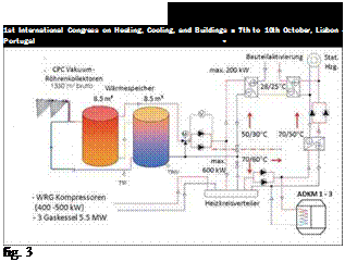 volume flow 30 m3/h
storage tank 17 m3
peak power 1.2 MW
max. continual power 0.65 MW
guaranteed yield 500 MWh per year
electrical energy req. 2.5 MWh per year
FESTO, hydraulic scheme, source (HfT-Stuttgart, FESTO AG)
According to the monitoring up to now this will probably be the first LSS that delivers more energy for the customer than the planners promised in advance.
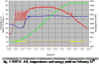 On sunny winter days nearly 4.3 MWh were fed into the tank at temperatures of more than 80 °C (fig. 4). These are after all 3.2 kWh per square meter gross collector area — an outstanding result for a day in February. No flat plate collector could probably reach the same result on a sunny day, not even in August.
In other installations an additional storage tank was expendable because the hydraulic system was able to absorb the solar input almost completely. This is very often the case in large industrial building complexes if the solar heat input can be absorbed permanently by the already existing instalment.
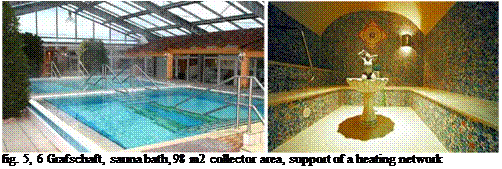 |
As a prototype a solar-thermal system for a large sauna bath has exactly been installed like an additional boiler (fig 5, 6). The solar heat is directly fed into the existing heating network (fig. 7).
solar application all-season support of an existing
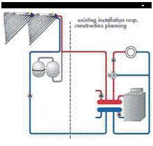 heating network at about 65 °C
collector area 98 m2 gross
storage tank none
guaranteed yield about 50 MWh or 500 kWh/m2
respectively per annum
electrical energy req. 380 kWh per annum
fig. 7 direct supply of hydraulic networks
The sauna bath installation proves that this hydraulic principle is easily usable for the most district heating networks. The prospects for this principle are very promising because professional solar support for district heating could be a huge business field in the near future.
 |
Many of non-spectacular but well-running systems like multifamily buildings, condominiums, hospitals, schools and gyms, hotels, restaurants, convention centres, barracks, prisons etc deserves to be especially mentioned, but that is impossible. All of them work amazingly simple because the heating water is also used as collector heat transfer fluid (fig. 8)
fig. 8 — large-scale solar-thermal systems for domestic hot water and space heating
At the end of the 90’s the conventional technique for solar-thermal collectors led in a dead end road. The flat plate collectors achieved high stagnation temperatures but the real efficiency for temperature ranges from 60 °C to 150 °C was not exactly promising. The problem of stagnating glycol-filled collector fields was enlarged. State of the art is that large-scale glycol-filled collector arrays must be prevented from stagnation situations by all means. Standard solutions are huge storage tanks which indeed partially solve the problem of stagnating collectors but in reality reduce the cost effectiveness considerably.
Paradigma has been involved the research and development of collectors since 1988 and launched the most innovative flat plate collectors on the market many years. In 1997 Paradigma treaded a new path and turned to vacuum tube technology. Today Paradigma has an ETC market-share of
50 % in Europe. The tubes were improved considerably, fitted in collectors from Paradigma’s own production and complemented with self-produced, high-precision CPC mirrors. This vacuum tube system is combined with minimal heat losses and ensures a very comfortable technical application on the building site. The technology to overcome the most serious problems concerning the use of water in all-year-round pressurized solar systems, which is frost protection, has been developed. Only with very high-efficient collectors with lowest heat losses it makes sense to prevent the collector field from freezing with a minimum of low temperature heat of about 2 % of the yearly solar energy gain. Operating temperatures of 60 °C — 130 °C can be achieved with high efficiency. The high sophisticated feeding algorithm provides the thermal energy at a temperature level which is preset by the user. So the solar systems operate like conventional boilers, the only difference is, that the solar irradiation is not steady.
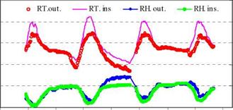
The evaluation of the hygrothermal behavior of the chamber was carried out together with agronomic trials during winter. The heated beds and the pipes in contact with the grafted area contributed to raise the temperature inside the chamber. Fig. 3 shows three consecutive days measuring: it can be observed how the chamber reaches maximum temperatures (RT ins.) of 30°C and minimum values of 10°C, while the temperature outside (RT out.) was between 22°C and 6°C. Inside temperatures were maintained within the recommended limits. The three days had similar radiation levels with 730W/m2 at the most. The relative humidity during the first and third day was observed to be similar comparing the inside (RH. ins.) and outside (RH. out) values; whereas on the second day, a significant increase of outside humidity at night was observed when there is a 4°C difference between inside and outside temperature, being the latter at the lowest values this day.
Rooting beds
D. Jaehnig*and W. Weiss
AEE INTEC, AEE — Institute for Sustainable Technologies, Feldgasse 19, A-8200 Gleisdorf, Austria
* Corresponding Author, d. jaehnig@aee. at
Abstract
This paper presents a method to design solar thermal systems for space heating of factory buildings using underfloor heating systems. The method uses nomograms that were expanded upon using simulations of typical system configurations. There are nomograms for two different systems configurations that can be used to determine reasonable values for collector and storage tank size for a factory building with a known heat demand.
These nomograms help to decide whether it is necessary to use a storage tank or if it makes sense to use the thermal mass of the concrete floor slab as heat store. The advantage of using the concrete floor slab is that the costs for a (often times large) storage tank can be saved. Further aspects covered are the necessity of an insulation layer underneath the floor slab and specific collector yields that can be achieved with the different system configurations. Keywords: space heating, factory buildings, design guidelines
Compared to other uses in buildings such as for domestic buildings, office and administrative buildings, factory halls are characterized by high room heights of 5 to 10 meters and relatively low room temperature requirements of 15 to 18 °С.
The heating demand in industrial halls is influenced by the insulation standard of the building and to a great extent by its use. High internal thermal loads, the frequent opening of hall doors, the supply of goods with a high storage mass, all of that influences the heating of halls quite considerably. Another important element is the fact that industrial halls mostly possess a very small storage mass — apart from the concrete flooring. On the other hand floor heating for industrial halls is becoming increasingly popular which once again favors the use of solar energy due to the low required flow temperatures.
To examine the influence of the different parameters on the heating of industrial halls, a reference hall was defined and different variants were compared via a simulation. Based on the parameter studies, design nomograms were prepared for typical cases in an analogous manner to the nomograms, which are used for solar thermal plants for hot water preparation and space heating.
The first estimation of the solar field is given by a simplified calculation of the performance of the thermosolar power plant, for what some information is needed:
* the location of the power plant,
* power block characteristics and
* the characteristics of the solar system (geometry, collector type, etc.).
The site where the solar thermal power plant will be built determines the geographical latitude and longitude, both necessary to know the incidence angle of the Sun, q>, on the aperture area of the solar field to design at noon and on the solstice. Using these variables in the power plant model
and assuming representative beam solar irradiance, Ed, and ambient temperature, Tamb, data at solstice noon at site, one can calculate the thermal power delivered by the solar field at that moment.
The power block determines the conditions (temperature and pressure) of the heat transfer fluid (HTF) at the solar field inlet and outlet as well as the required thermal power. The inlet temperature is set by the temperature of the condensed water from the Rankine cycle. The outlet temperature will be limited by the maximum bulk temperature of the solar field working fluid. On the other hand, the nominal electric power of the steam turbine determines the required thermal power, taking into account the efficiency of the whole thermal cycle, including not only the turbine but also the heat exchanger and the internal electric consumption for running the plant (around 10 %).
Solar field characteristics include the technical specifications of the chosen collector. These specifications include both dimensions — like its length and aperture width, the inner and outer diameter of the absorber tube and the roughness of its steel pipe — and thermal performance parameters — like peak optical efficiency, t]op0, incidence angle modifier, K(q), and heat losses, Qloss. A soiling factor, Fe, is also included in order to have an estimation of the influence of maintenance strategy on the solar field performance.
The orientation of the collector axis depends, mainly, on the pattern of plant operation and it can be limited by the size and geometrical shape of the plot available for the plant. The most used options are the North-South and the East-West orientation: while the North-South orientation produces a larger amount of energy annually, the East-West orientation gives less difference in energy output between summer and winter days.
The pre-design of the solar field consists of the calculation of the number of collectors per row and the number of rows needed to meet the nominal conditions required by the steam turbine, taking into account the information mentioned in the previous paragraphs. The number of collectors per row is a function of the temperature increase between the input and output of each row for what the temperature increase in every collector of a row has to be calculated assuming a nominal mass flow that guarantees a good heat transfer coefficient in the absorber tubes. The number of rows depends on the thermal power provided by every row and the total thermal power to be given to the Rankine cycle.
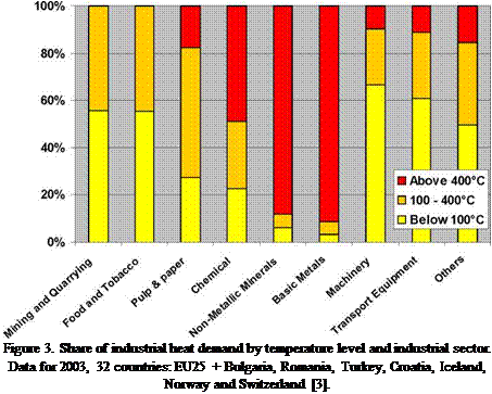 |
The “ECOHEATCOOL” study [3] reports that about 30% of the total industrial heat demand is required at temperatures below 100 °C and 57% at temperatures below 400 °C. Moreover, in several industrial sectors, such as food, wine and beverage, transport equipment, machinery, textile, pulp and paper, the share of heat demand at low and medium temperature (below 250 °C) is about, or even above, 60% of the total figure. However, it should be highlighted that the pulp and paper sector uses primarily heat recovery systems and, therefore, even though the theoretical potential is high, the practical implementation of a solar thermal plant is not convenient in most of the cases. The figures obtained from industry statistics are fully confirmed by the outcomes of the estimates done in the reported potential studies for solar process heat.
Finally, it should be noted that quite often industrial processes exploit medium temperature heat by using steam as a heat carrier even though lower working temperatures would be sufficient.
Therefore, in order to assess correctly the feasibility of the introduction of solar thermal in an industrial process, one should look at the actual temperature needed by the process itself and not at the temperature of the heat carrier being used. Such an approach should be used not only for determining the implementation of solar thermal plants, but also for lowering the current process energy consumption.
In order to describe the woodchip drying curves and study how the drying factors affect, a series of tests were conducted at different temperatures and velocities.
Drying is the process of removal water from a product. As a thermal process, the performance of any dryer mainly depends on the construction, design parameters as well as the operating conditions: flow rate and heat input [7]. During the tests, the weight of the sample, flow rate and psychrometric parameters: temperature and humidity were measured periodically using the appropriate instrumentation.
Sets of tests were undertaken at different temperatures, between 10°C and 50°C, for different drying velocities. The experimental drying velocities tested on the tray (area 0,25 m2) were up to 0.25 m/s that correspond to an air flow rate of 280 m3/h.
For each test, 3 kg of woodchip at 52% MC were spread over the tray forming a thin layer of 3 cm thickness. The woodchip was stirred to facilitate uniform drying. The sample weight was measured at 2 minutes intervals by a precision scale. Moisture content decreased until it reaches the equilibrium with the ambient. At the end the sample was dried up in an oven at 105°C. The ambient lab conditions were steady during the tests; temperature and relative humidity remained initial levels through the test.
The performance of the dryer was expressed the rate of water content with the product weight in the drying curves. Figure 2 shows the experimental variation of MC with time for selected tests at different drying conditions described in Table 1. As it is expected, MC decreases with increasing drying time describing an exponential curve. Drying time decreases as temperature and flow rate increase.
|
Table 1: characteristics of the tests used for the drying model
|
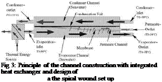
![]() For the design of a solar-powered desalination system, the question of energy efficiency important, since the investment costs mainly depend on the area of solar collectors to be Also, the power consumption of the auxiliary equipment (for example the pump) which will be supplied by photovoltaic (PV) has an important influence on the total system costs. Therefore, the system design has to focus on a very good heat recovery function to minimize the need for thermal energy. Heat recovery can be achieved by an external heat exchanger or by an internal heat recovery function, where the feed water is used as coolant for the condenser channel. The internal construction principle respectively the spiral wound geometry of the MD module with integrated heat recovery is shown in figure 3.The technical specifications of the MD modules constructed by Fraunhofer ISE are:
For the design of a solar-powered desalination system, the question of energy efficiency important, since the investment costs mainly depend on the area of solar collectors to be Also, the power consumption of the auxiliary equipment (for example the pump) which will be supplied by photovoltaic (PV) has an important influence on the total system costs. Therefore, the system design has to focus on a very good heat recovery function to minimize the need for thermal energy. Heat recovery can be achieved by an external heat exchanger or by an internal heat recovery function, where the feed water is used as coolant for the condenser channel. The internal construction principle respectively the spiral wound geometry of the MD module with integrated heat recovery is shown in figure 3.The technical specifications of the MD modules constructed by Fraunhofer ISE are:
• hydrophobic membrane, mean pore size 0.1 — 0.4pm
• height 450 — 800 mm
• diameter 300 — 400 mm
• membrane area 7 m2 — 12m2
• feed temperature at evaporator inlet 60 — 85 °C
• maximum feed volume flow 500 l/h
• specific thermal energy consumption 100 — 260 kWh/m3distillate
•
 |
 |
distillate output 10-40 l/h
Since 2003 PARADIGMA has been using water as heat exchange medium with the so called AquaSystem. Frost protection is ensured by unutilized low-temperature heat from the installation. Because of the low heat losses of the CPC vacuum tube collectors only a small amount of energy (about 2 to 4 % of the yearly gain in energy) is required for frost protection and this is more than compensated by the advantages of using water and high operating temperatures. This concept has proven successful more than 30,000 times so far.
The advantages of the AquaSystem over conventional solar collector systems are obvious. The operation with water:
allows easy, direct connection to the in-house heating network,
requires less equipment such as heat exchangers, de-aerators, valves, pumps and controllers,
is the precondition for the use of efficient and small storage tanks,
eliminates the high costs for antifreeze and the associated running costs,
reduces considerably the costs and time for commissioning and repairs,
ensures a long operating life with almost constant performance,
removes all risks associated with thermal stagnation and
minimizes running costs (e. g. maintenance).
The use of state of the art CPC vacuum tube collectors ensures the maximum harvesting of solar energy with a system that has a long operating life and is virtually maintenance free.
It is absolutely unscientific that the power investigations according to DIN EN 12975 (see chapter 7 “power performance…”) were carried out with water without any consideration of the heat transfer fluid propylene glycol which is normally used. Glycol has with 40 °C compared with water only 88 % of the heat capacity, 3.8 times the viscosity, 62 % of the heat conductivity, only a quarter the Reynolds number (therefore these collectors must work at unfavourable, laminar flow conditions), 75 % of the heat-transfer coefficient and up to 3.85 times higher pressure losses. And the deeper the temperatures are the worse the glycol conditions. A water-glycol heat exchange requires up to 3 times the heat exchange area than a water-water heat exchange to get the same NTU (number of thermal units). Nearly all simulations programs for solar harvest and almost the whole solar literature disregard this physical context, e. g. by use of too simple models.
The control system is based on the comparison of a reference temperature (ref. T) and that of the water circulating in the pipes of the bed, 30 — 35°C. The reference temperature is that fixed in the sensor placed on one of the collectors. During the day, provided there is radiation (ref. T > 32 °C), the control system (electrovalves) orders the water circulation through the collectors and the hot water tank until it reaches the beds. In case there is no radiation (at night or cloudy days), water does not circulate through the collectors but goes directly to the hot water tank where it takes the
required temperature. A sensor inside the hot water tank records the switching on and off which allows to determine the time spent for the operation and the energy consumed.

![]()
![]()
![]()
 о
о
Q__ |
a
a
E
и
&
a
и
H
Fig.3. Hygrothermal behavior of the propagation chamber during winter.
![image263 Подпись: Fig. 4 shows the outdoor conditions during the days when the trials were conducted, the first three and the fifth day were clear with a horizontal radiation between 830 and 900 W.m-2, while the fourth and sixth day it was between 270 y 350 W.m-2 respectively by midday. The temperature outside (RT.out.) was between 8 °C and 35 °С. Time [hs ]](/img/1153/image263.gif) |
To analyze the functioning of the system, several measures were taken during six consecutive days: on the first two days, the system functioned automatically according to prefixed ranges; on the third and fourth day, the water pass was closed by the collectors in order to evaluate the hot water tank switching on and off time. The following days, the system worked automatically.
Fig.4. Outdoor temperature and radiation during the trials
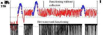
Fig. 5 shows the water temperature when water comes out of the solar collectors and the hot water tank. On the first days, when the system functioned combining sun — gas, the hot water collectors contribution started at 11 am and lasted until 6 pm. During this time, the sensor placed in one of
the collectors allowed water passing from the beds. When the temperature (32 °С) recorded by the sensor decreases, it closes the electro valve, and water passes only to the hot water tank, previously regulated to maintain the temperature required by the rooting process. On the third and fouth day, the water flow was operated manually, closing it for the collectors so as to be able to compare the energy consumption of the hot water tank. On the last two days, the system was again regulated automatically: on the fifth day (clear sky) water was provided by the collectors for six hours. The last day, with a maximum solar radiation of 350 W. m-2, the collectors provision was null; for this reason, the hot water tank worked all day.
The records about the hot water tank switching on (1) and off (0) time make it possible to determine the operating time and the consumption.
![]() 5
5
45
 |
40
Fig.5. Water outflow temperature from the collector and from the hot water tank during the trials
 40 38 36 О 34 32 30 28 26 24 22 20
0 8 16 2 4 32 40 48 56 64 72 80 88 96 104 112 120 128
Time [hs]
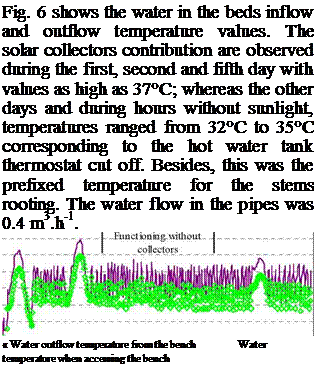
Fig.6. Water inflow and outflow temperature on the benches and water outflow temperature from the hot
water tank
The walnuts (seeds) were sown on the bed with a 22°C basal heating. Germination occurred 30 days after sowing, with a 70% of success. 45 days after germination, the vegetal material was transplanted to black plastic bags which were placed on the same bed. When the plants were about
0. 30 m high and had a 0.05 stem diameter, the grafting process started.
The pots with the grafted plants were put on the benches with basal heating, and two pipe lines were added to both sides of the grafting zone, 0.05 m away from the grafting area while water circulated through them heated between 28°C and 31°C. This temperature was maintained during the cicatrization process until buds came out about 21 days later.
Though the relative room humidity values were adequate, transparent plastic bags were used to cover the cicatrization zone and the graft to ensure the maintenance of the recommended humidity values (Fig. 7). The stem taking results, obtained from 100 grafted walnuts using four different grafting treatments (25 grafts per treatment), were 48%, 84%, 16% y 56%.
|
Fig.7. Inside view of the chamber with the grafted walnut young plants and the carob stems |
Stems from the basal part of the branch were taken with a length of 0.25 to 0.30 m and a diameter of 0.0025 a 0.0030 m. Each stem had 4 to 5 buds and some leaves cut in halves to diminish transpiration. At the base of the stem, a scraping was made to leave the bark exposed and with a wider contact surface with the hormone solution to be used.
The hygrothermal behavior of the chamber used simultaneously for walnut grafting and carob rooting was highly satisfactory, obtaining temperaturas and humidities appropriate to the requirements for the production of both species.
Two trials were carried out using three types of IBA concentrations (6000, 8000 y 10.000 ppm). Fr each concentration, 50 stems were placed on the bench with the plastic tunnel with a substrate temperature of 32°C.
The results elicited showed a direct relation with the type of treatment applied, obtaining a 40% callus formation and a 20% rooting of the stems treated with 8.000 ppm concentrations. The stems which took roots were the ones to maintain the leaves with rooting callus formation 25 days after the treatment. Better results were obtained with the stems treated with 10.000 ppm, where the
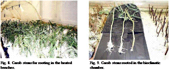 |
percentage of callous stems was 60%, with a 30% of rooting. The rooting of stems which did not lose their leaves occurred 20 days after the treatment (Fig. 8).
From the agronomic point of view, the results were those expected because the chamber could be maintained within the limits of the required environmental conditions. Callus formation was accelerated by the heat treatment on the cicatrization zone, a controlled process to avoid the live tissue destruction due to possible excess temperature levels.
The inclusion of the plastic tunnel significantly improved the hygrothermal room conditions of the carob stems. Such tunnel enables the independent work of the hydrocooling humidity and the surrounding environment, so that the humidity in the tunnel basically depends on the irrigation micro sprinklers contribution.
The results also give the means to analyze the sun — gas system behavior for the rooting benches heating. From the thermal point of view, the achievement of the expected results makes it possible to have an adequate resource for stems propagation.
[1] Moraldi M. y Lanzi, P. (1993). Il riscaldamento localizzato dell’ innesto nella produzione vivaistica del noce. Rivista di Frutticoltura, N° 1, pp 53 — 556.
[2] Iriarte A., S. Bistoni, L. Saravia. "Modelo de prediction del comportamiento de colectores solares plasticos para calentamiento de sustratos en invernaderos". Revista Avances en energias renovables y medio ambiente, Vol. 6, N° 2, pp. 02.37 — 02.42, 2002.
[3] Felker, P. 1980. Niitrogen cycling-water use efficiency interaction in semi-arid ecosystems in relation to management of tree legumes (prosopis). IN International Symposium on Browse in Africa. Pp.214-222.
[4] Garcia V., Iriarte A., Lesino G,, Flores S., Matias C. (2003). Comportamiento termico de una camara para microinjertacion de plantines de nogales. Avances en energias renovables y medio ambientes. Vol. 7, pp. 2.19 — 2.24.