Как выбрать гостиницу для кошек
14 декабря, 2021
Сегодня каждый, кто собирается в отпуск и не знает, с кем оставить своего котика или кошку, может во[...]
The configuration of a solar combi+ system with seasonal storage (SST) has shown interesting results in terms of solar fraction since it can practically reach 100% of energy demands for domestic hot water, space heating and cooling. As expected, the cost of the HIGH-COMBI system (referred to as system “A”) is substantially higher compared with system “B” (same collectors area but without SST), but comparable with system “C” (a larger collectors’ area combi+ system with similar solar fraction). Consequently, solar systems with relatively small SST could be a valid option for high solar fractions.
In fact the alternative (to the SST) solution with similar solar fraction (solution C) presents various disadvantages; the most important being the increase of the solar collectors area (twice as big compared with “A”) which may exceed the available space (e. g. building’s roof area).
The following aspects have been identified in order to further investigate the concept presented in the current work:
Ground heat exchangers (GHE) around the SST should be simulated in order to identify an optimal combination of SST volume, insulation and GHE length and geometry.
The use of low cost thermal insulation materials (to lower the U-value) should be further analyzed.
The optimization procedure should include more variables such as the type and control for the heating/cooling delivery system, the solar collectors, SST insulation aspects (especially if GHE are implemented) etc.
The use of an adsorption heat pump (HP) as the auxiliary heating and cooling source should be examined as it may allow taking full advantage of the SST (extending its use in summer time). Moreover, this combination may lead to a 100% renewable energy coverage of the heating/cooling
demands with a smaller and cheaper plant. In this case, the solar gains should be enough for driving the HP in summer (keeping the SST at lower temperatures) but when there is not enough solar radiation for heating in winter then the HP could be driven by a biomass boiler or, simply, by a fireplace. In this way the HP will cool the tank and may create even an inverse heat flow from the ground into the tank. The solar collectors’ efficiency will obviously increase substantially.
Finally, it will certainly be interesting to examine similar systems in energy and financial terms in other Mediterranean and/or central European countries
Acknowledgments — The High-Combi project (www. highcombi. eu, 2006-2010) is partly financed by the European Commission (6th Framework Programme, EC DG TREN) and is a collaborative effort of 12 partners from 6 European countries.
Thanks are due to all High-Combi partners and especially to those that have contributed directly or indirectly to this work. Particular thanks to Thomas Schmidt, Tomas Nunez, Jochen Doell and certainly to Thomas Paushinger & Co, as well as to Anastasia Benou for their (not only technical) support. Last but not least, many thanks to professors Petros Ditsas and Stefanos Trahanas for teaching the art to distinguish what is essential and what superficial.
Balaras C. A., Grossman G., Henning H-M, Ferreira C. A.I., Podesser E., Wang L., Wiemken E., 2007, Solar Air Conditioning in Europe — An Overview, Renewable & Sustainable Energy Reviews, Vol. 11, No 2, p. 299-314.
ESTIF 2007, Solar Thermal Action Plan for Europe, 26 p., European Solar Thermal Industry Federation, Brussels.
Koldehoff W. B., The Solar Thermal Market, Status-Technologies-Perspectives, BSW German Solar Industry Association (MoB), 2008
Schmidt T., Mangold D., Muller-Steinhagen H., 2004, Central solar heating plants with seasonal storage in Germany, Solar Energy Volume 76, Issues 1-3, January-March 2004, p. 165-174, Solar World Congress.
Solair 2008, Intelligent Energy Europe project, www. solair-vroiect. eu
TRNSYS 16, 2006. A Transient System Simulation Program. Reference Manual. Solar Energy Laboratory, University of Wisconsin-Madison.
Weiss W, Bergmann I., Faninger G., Markets and Contributions to the Energy Supply 2006, Solar Heat Worldwide Edition 2008,
H. A. Zondag1*, Alex Kalbasenka1, Martijn van Essen1,
Lucas Bleijendaal1, Roelof Schuitema1, Wim van Helden1, Lucienne Krosse2
1 ECN, Energy Research Centre of the Netherlands, P. O. Box 1, 1755 ZG Petten, The Netherlands
2TNO, P. O.Box 342, 7300 AH, Apeldoorn, The Netherlands
* Corresponding Author, Zondag@ecn. nl
Abstract
This paper summarises the findings of a parameter study on a TCM reactor, and in addition presents first calculations on the dimensioning of three concepts for dehydration reactors.
Traditional heat storage techniques have a number of disadvantages for long-term heat storage, such as substantial heat loss and relatively low energy density (large volume). As an alternative, it is possible to store energy by means of chemical processes in thermochemical materials (TCM), making use of the reversible chemical reaction A(s) + B(g) О C(s) + heat. Interesting reactants are low cost, non-toxic, non-corrosive, have sufficient energy storage density and have reaction temperatures in the proper range. These requirements are fulfilled by a number of salt hydrates. In a previous study (Visscher et al., 2004), magnesium sulphate has been identified as a potentially interesting storage material, by means of the reaction MgSO4(s) + 7H2O(g) О MgSO4x7H2O(s) + 411 kJ per mole of MgSO4. This material could be interesting for seasonal storage of solar heat. During winter, when heat is needed for e. g. residential heating, the magnesium sulphate is hydrated, producing heat. During summer, the hydrate is dehydrated by heat from a solar collector, which can be regarded as charging of the material. Once the chemical reaction has taken place, the solar heat can be stored in this way for a long time period without losses.
M. G. Lima, A. Joyce, J. Milhazes, D. Loureiro*
INETI, Department of Renewable Energies, Campus do Lumiar INETI, 1649-038 Lisbon, Portugal
Corresponding Author, scientific. comm@eurosun2008.org
Abstract
A Salt Gradient Solar Pond (SGSP) is a salt water basin that collects and stores solar energy. These devices rely on the existence of a non-convective zone (NCZ) that functions as a transparent thermal insulation zone, created by a salt gradient. Salinity and temperature gradients in this zone can give rise to double diffusive problems that can decrease the insulation properties of this zone.
The stability of this zone is thus crucial in a SGSP.
Stability control, analysis of energy extraction, device efficiency and maintenance strategies are determinant for the correct performance of the SGSP. The implementation of these strategies can be expensive and not sufficient to prevent instability problems. This paper intends to give a contribution to the maintenance problem presenting a new concept of a SGSP utilisation: The Dual Solar Pond (DSP)
Keywords: Solar Pond, stability, maintenance.
A Solar Pond is a salt water basin that collects and stores solar thermal energy. These devices are based on the prevention of free convection, either by increasing the solution’s viscosity, or by the establishment of a salinity gradient that opposes the adverse temperature gradient, induced by solar radiation absorption. Most existing Solar Ponds are based on this last type. The working of a Salt Gradient Solar Pond settles in the stability of its non convective zone, where salinity and temperature gradients are established and where physical instabilities may occur as a result of double diffusion phenomena. There are several models that analyse the behaviour of this zone. These models allow the control and prevention of any perturbations capable of triggering an instability process. For the study here presented it will be considered a simplified structure of a SGSP with two zones: the gradient non convective zone (NCZ) and the storage zone (SZ) as it is depicted in Figure 1. It was considered that the Storage Zone is nearly saturation in terms of concentration (25 % in salt) and that the top of the gradient zone has a concentration near of that of sea water (3%).
ц
Presently Solar Pond studies focus on stability control of the non convective zone, analysis of energy extraction, device efficiency and maintenance strategies as in the works of [1], [2], [3], [4], [5], [6] and others.
Applications of Solar Ponds are very important especially for Mediterranean countries and go from greenhouse or livestock structures heating, aquaculture heating, salt purification and water desalination processes and even electricity production, using Rankine cycle engines. All these applications are an opportunity to economic development of near coast regions using local resources (seawater, salt and solar energy) and promoting employment. Concerning environment these solar applications could achieve an integrated way to the mitigation of GEE with low environmental impacts.
The precise SEM investigations in different areas of the composite micro-volumes let elemental analysis of the eutectics crystallization into salt/graphite composites. The EDS imaging, made at magnification X30, proved preferable elemental areas of Na; K; N2; O2; C distribution during eutectics salt cooling into the graphite matrix.(Table 4).
The EDS element mapping confirmed both, potassium-rich and sodium-rich areas exist. The sodium-rich phase solidifies in rounded areas of up to 3 pm across, but the potassium-rich phase solidifies on the plane graphite surface. The composition ranging from high in Na to high in K nitrates areas, both with smaller concentrations of the other constituent The elemental separation of eutectics salt of the salt/graphite composite on solidification in two phases leads to the considerable segregation of the two chemical components and impact the salt crystallization and thermal capacity of the composite.
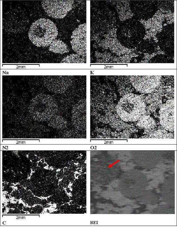 |
Table 4. Elemental images made by EDS of the NaNO3/KNO3eutectics/graphite (20%) composite. Brighter areas indicate distribution of the chemical elements: Na, K, N2, O2 and C, respectively.
Two types of ployalcohols groups can be distinguished (Fig. 1). On the one hand, sugar alcohols
such as erythritol (C4H6(OH)4), mannitol (C6H8(OH)6) and galactitol (C6H8(OH)6) with a solid — liquid phase change have been suggested [10]. Hakiuchi et al. examined the long-term thermal stability of the sugar alcohol erythritol with a melting temperature of 120°C. Experiments in a sealed steal container showed a degradation process of erythritol upon heating already slightly above the melting temperature [10].
On the other hand, there are polyalcohols, known as plastic crystals undergoing a solid-solid transition. Examples are tris(hydroxymethyl)aminomethane (TAM, H2NC(CH2OH)3) and pentaerythritol (PE, C(CH2OH)4) [11]. For latent heat thermal energy storage systems, PE has often been suggested as a PCM [1,5,6,12,13]. PE has a solid-solid phase transition at around 190 °C and a melting temperature of about 260 °C [14]. PE has a high vapour pressure and sublimes on heating in the solid phase (100 Pa at 195°C and 154 Pa at 204°C)[15]. Hence, for the PCM application PE needs encapsulation. Sakamoto reported about an experiment of PE in a sealed glass container at 195-200°C for 1000 hours. Little changes in the phase transition temperature and a slight drop (about 90% of the initial value) in enthalpy were reported [16]. Different mixtures of PE with other polyalcohols have also been examined. The transition temperatures of these mixtures are mainly below 120°C, so that they are not considered here [12].
High density polyethylene (HDPE) with a melting temperature of about 130°C has been often proposed as a PCM [1,5,7,8,10,12,17,18,19]. Polyethylene as a PCM has been used for small size electrical stoves in Japan [10]. HDPE can be of the cross-linked type in order to get form-stable materials in the liquid phase. A crosslinked HDPE pellet bed has been used in direct contact with an ethylene glycol/water solution. This solution acted as heat transfer medium undergoing pool boiling and condensation [19]. Takahashi reports molten Polyethylene to be not stable in air, but stable in the absence of oxygen [20]. In a 500 h degradation test, sealed polyethylene showed little change in melting and crystallization temperature, as well as latent heat [21]. For crosslinked HDPE undergoing 100 thermal melting and solidification cycles, no change in melting temperature and heat of fusion was detected [17].
Benzoic Acid (BA, C6H5COOH) and its derivatives have been proposed [1,5,12,22](Fig. 1). They derivatives include 4-Methyl-BA, 4-Amino-BA and 4-Chloro-BA. BA has been suggested as a calibration substance for Differential Scanning Calorimetry (DSC), where hermetically sealed crucibles are required [23]. BA has a melting temperature of 122°C. It has a high vapor pressure and sublimes at about 100°C (820 Pa at 123°C, 1330 Pa at 132°C, 13300 Pa at 186°C — water for comparison: 3170 Pa at 25°C) [14,23]. Upon heating to 150°C, some dehydration takes place to form benzoic anhydride [14].
Other PCMs, such as Urea (CO(NH2)2) have been also proposed. [1,5]. Urea decomposes upon heating above the melting temperature and hence is not suitable for thermal energy storage [13,14].
W. Streicher1*, A. Heinz1, J. Bony2, S. Citherlet2, L. Cabeza3, J. M. Schultz4, S. Furbo4
1 Graz University of Technology, Institute of Thermal Engineering, Inffeldgasse 25b, A-8010 Graz, Austria
2 HEIG-VD, Route de Cheseaux 1, CH-1400 Yverdon-les-Bains, Switzerland
3 Escola Universitaria Politecnica, Universitat de Lleida, Research Group on Applied Energy, Jaume II, 69,
SP — 25001 Lleida, Spain
4 Department of Civil Engineering, Technical University of Denmark, Brovej, Building 118, DK-2800 Kgs.
Lyngby, Denmark
* Corresponding Author, w. streicher@tugraz. at
Abstract
Phase change materials (PCM) as heat storage theoretically offer an advantage compared to water stores on the one hand, when the cycling temperature is close around the phase change temperature and the phase change can be used quite often. Another application is the use of the subcooling effect of certain PCM for seasonal storage. The scope, in terms of general system aspects for IEA SHC Task 32, was solar heating and cooling systems for residential buildings, principally detached houses for one up to a few families. Additionally other promising heating or cooling systems were taken into consideration. Five projects dealing with PCM modules in solar combistores, seasonal storage with subcooled PCM and PCM in residential heating systems as space heating stores were investigated in the laboratory and by simulation studies. However, the investigations reported here showed only little advantages for macro-encapsulated PCM modules in combistores, PCM-stores with immersed heat exchangers and for PCM slurries for heat stores in solar combisystems and residential heating systems. The seasonal storage with subcooled PCM could be in principle a good solution. However the technical expenditure for this system is large.
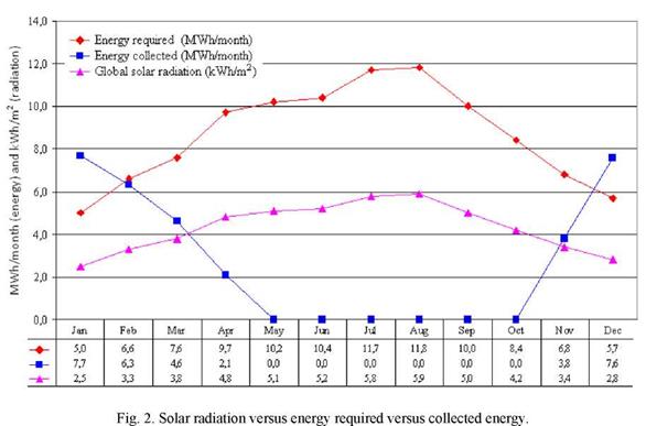
The panels to be used in this 300 m2 greenhouse will have a total of 108 m2 of ethylene propylene diene monomer (EPDM) unglazed collectors, from SUNTEK industries [5]. The collectors will be placed inside the greenhouse, against roof sections having an inclination of 60° with the horizontal, which will turn them in a sort of glazed type collector. Figure 2 presents monthly energy collected with these thermal solar panels. From the results it can be expected that approximately 27.407,8 kWh/year (85,5%) will be saved with the use of this technology in our standard 300 m2 greenhouse without any additional thermal improvement, such as thermal curtains or floor heating systems.
From May to October, when the solar energy collected is more than what is required, the inclination of the solar collectors can be modified, with the consequent reduction of the energy in excess. Figure 2 shows the energy profile along a year of the solar radiation versus energy required versus collected energy (collectors tilted 60°).
|
|
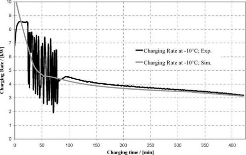
Charging and discharging processes where calculated in EES and Matlab and validated with experimental Data. Figure 8 compares the simulated and experimental progress of the charging rate at a charging temperature of -10°C. With the exception of the starting-period, the agreement between measured and predicted values is very good. For the starting period, the simulation predicts an average value without the artificial fluctuations caused by the thermostat.
|
|
Q cond |
Conducted heat flow rate, |
W |
|
• Qlat |
Latent heat flow rate, |
W |
|
• Q kon |
Convective heat flow rate, |
W |
|
^■ice |
thermal conductivity of ice layer, |
W/(mK) |
|
A. -T^ice |
Outer surface of ice layer, |
m2 |
|
rice |
Radius of ice cylinder, |
m |
|
Ahs |
latent heat of solidification, |
kJ/(kgK) |
|
mice |
Mass of ice, |
kg |
|
pice |
Density of ice, |
kg/m3 |
|
aout |
heat-transfer coefficient, |
W/(m2K) |
|
Ltube |
Length of tube, |
m |
|
Temperature of liquid water, |
°C |
|
|
Temperature at ice surface, |
°C |
[1] Brendel, T., Spindler, K., Muller-Steinhagen, H.: Aufbau einer Versuchs — und
Demonstrationsanlage zur solaren Kuhlung, DKV Jahrestagung Bremen, 2004, S. 105-118
[2] Hilligweg, A.: Vordimensionierung von Eisspeichern; TGA Fachplaner 6-2003; S. 29
[3] Streit, D.: Freie Konvektion am horizontalen Rohr in einer Kies/ Wasser-Schuttung mit Bildung und Schmelzen von Eis; Dissertation; 1996; S. 59
|
Sand flow analysis showed blocking behaviour of the sand starting from the air outflow side, when a critical air flow velocity was exceeded. The blocking increases with growing air flow velocity and a decrease of sand grain size, see Fig. 4. Fig. 4 Blocking of sand flow starting from the air outflow side (left side), sand grain size: 0.4-0.8 mm, Averaged air inflow velocities: 0.4 m/s (left figure), 1.1 m/s (middle), 1.9 m/s (right) |
 |
After mounting of the steel screens the heat transfer was to be analysed. According to the simulation results a cross flow specific temperature field, as shown in Fig. 2 with a high sand outflow temperature and a low air outflow temperature was expected. Different from this fluctuating sand and air outflow temperatures were measured indicating discontinuous sand flow.
As a consequence to ensure steady and efficient heat exchanger operation, the critical air velocity specific for each sand grain size must not be exceeded.
|
Figure 9. Mesh for Tanks 2 to 4 Figure 10. Mesh for Tank 5 Figure 11. Mesh for Tanks 6 and 7 |
 |
Geometric similarities between Tanks 2 to 4, and between Tank 6 and 7 resulted in the generation of only three new meshes, in addition to those of the original study. These are illustrated in Figures 9 to 11 with a summary of all mesh details provided in Table 2.
|
Tank ID |
|
Dimensions (# Faces, plane x # Nodes cyl) |
|
Equiangle Skewness (< 0.5) |
|
Number of Cells |
Table 2. Characteristics of Developed Meshes