Как выбрать гостиницу для кошек
14 декабря, 2021
Сегодня каждый, кто собирается в отпуск и не знает, с кем оставить своего котика или кошку, может во[...]
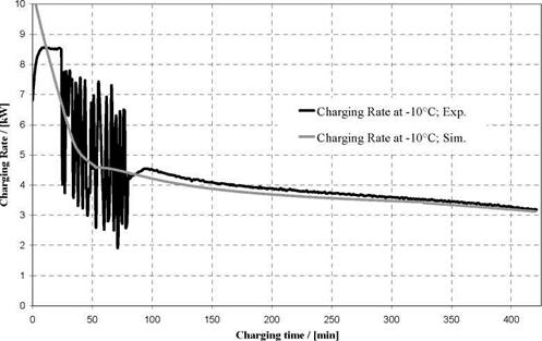
Charging and discharging processes where calculated in EES and Matlab and validated with experimental Data. Figure 8 compares the simulated and experimental progress of the charging rate at a charging temperature of -10°C. With the exception of the starting-period, the agreement between measured and predicted values is very good. For the starting period, the simulation predicts an average value without the artificial fluctuations caused by the thermostat.
|
|
Q cond |
Conducted heat flow rate, |
W |
|
• Qlat |
Latent heat flow rate, |
W |
|
• Q kon |
Convective heat flow rate, |
W |
|
^■ice |
thermal conductivity of ice layer, |
W/(mK) |
|
A. -T^ice |
Outer surface of ice layer, |
m2 |
|
rice |
Radius of ice cylinder, |
m |
|
Ahs |
latent heat of solidification, |
kJ/(kgK) |
|
mice |
Mass of ice, |
kg |
|
pice |
Density of ice, |
kg/m3 |
|
aout |
heat-transfer coefficient, |
W/(m2K) |
|
Ltube |
Length of tube, |
m |
|
Temperature of liquid water, |
°C |
|
|
Temperature at ice surface, |
°C |
[1] Brendel, T., Spindler, K., Muller-Steinhagen, H.: Aufbau einer Versuchs — und
Demonstrationsanlage zur solaren Kuhlung, DKV Jahrestagung Bremen, 2004, S. 105-118
[2] Hilligweg, A.: Vordimensionierung von Eisspeichern; TGA Fachplaner 6-2003; S. 29
[3] Streit, D.: Freie Konvektion am horizontalen Rohr in einer Kies/ Wasser-Schuttung mit Bildung und Schmelzen von Eis; Dissertation; 1996; S. 59