Как выбрать гостиницу для кошек
14 декабря, 2021
Maria Joao Carvalho ^ and Ana Neves 1
1 INETI, Department of Renewable Energies, Campus do Lumiar do INETI, 1649-038 Lisbon, Portugal
* Corresponding Author, mioao. carvalho@ineti. pt
In the frame of European Directive for Energy Performance in Buildings, EU Directive 2002/91/CE, Portugal produced legislation transposing the EU Directive and imposing the usage of thermal solar systems for hot water preparation. The energy necessary for the preparation of hot water constitutes one of the terms for evaluation of energy performance of the building. The calculation methodology is incorporated in a software tool developed by INETI and called SolTerm. At the end of 2007, CEN also published a set of standards, EN 15316, covering “Heating systems in buildings and methodologies for calculation of system energy requirements and system efficiencies”. In this set of standards, part 4-3 is dedicated to Thermal Solar Systems and introduces a calculation methodology for determination of the energy delivered by a thermal solar system. The present work compares the results of both methodologies and shows that the difference between the two methodologies is mainly dependent on collector efficiency parameters, due to the limits of application of the methodology of EN 15316, based on f-chart method.
Keywords: thermal solar systems, hot water preparation, heat delivered, building energy performance.
1. Introduction
In the frame of European Directive for Energy Performance in Buildings (EPBD), EU Directive 2002/91/CE, Portugal produced legislation transposing the EU Directive. This legislation went in force in April 2006 and included a Solar Thermal Obligation. This obligation is present in the new Portuguese Thermal Performance Building Code (RCCTE) [1], imposing the usage of thermal solar systems for hot water preparation if there are favourable conditions of exposure (if the roof or cover runs between SE and SW without significant obstructions) in a base of 1m2 per person (that can be reduced up to 50%, in certain conditions).
In the Portuguese legislation, the energy necessary for the preparation of hot water constitutes one of the terms for evaluation of energy performance of the building, as well as, the heating and cooling loads of the building.
This term takes into account the positive contribution of the use of a thermal solar system for hot water preparation. To take this into account it was necessary to establish a calculation methodology for the energy delivered by the thermal solar system. This methodology is incorporated in a software tool developed by INETI and called SolTerm [2].
At the end of 2007, CEN also published a set of standards, EN 15316 [3], covering “Heating systems in buildings and methodologies for calculation of system energy requirements and system
efficiencies”. In this set of standards, part 4-3 is dedicated to thermal solar systems and introduces a calculation methodology for determination of the energy delivered by the solar system.
The present work compares the results of both methodologies and establishes the conditions in which it is possible to consider that they give an equivalent input to the calculation of energy needed for hot water preparation and the energy performance of the building.
In Section 2, a short description of both calculation methodologies is presented. Section 3. highlights the specific aspects of the Portuguese legislation that are relevant for the calculation of the energy contribution of the thermal solar system to the building energy performance. The results of calculations made for different situations are presented in section 4. Final conclusions are presented in section 5.
The described semi-transparent collector is a multifunctional architectural design element. This offers a new market potential for solar thermal energy use. At a certain distance the structure of the small openings appears as a homogeneous semi-transparent area with the silhouette of the channels. This offers interesting possibilities in design: straight vertical or horizontal channel arrangements as well as curved designs such as in a FracTherm® absorber [5] can be realized if roll-bonding or another production method with similar flexibility is used.
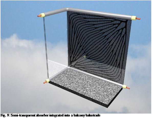 |
Office buildings often feature large glazed fa? ade areas and need appropriate devices for solar control and glare protection. Moreover, cooling becomes more and more important. Provided that the collector efficiency and thus the temperatures will be high enough, it will be possible to use them to drive a solar cooling system. This could also be done floor by floor, since the collectors are nearby the room with the cooling load. The collectors can also be used in hotels, hospitals or sanatoria where both an effective solar control and a high amount of domestic hot water as well as heating water are needed. A special application is shown in Fig. 9, where the semi-transparent absorber is integrated into a balcony balustrade with the insulated flow and return pipes covered by a stainless steel handrail.
4. Outlook
The multifunctional collector is still in an early stage of research and development. The necessary work will be carried out as part of a large European research project together with industry partners.
The main challenges will be the following:
• maximization of the absorber efficiency (efficiency factor F’ and insulation of the collector, which is also necessary in order to prevent the room from overheating)
• characterization and optimization of the collector as a classical solar collector (incidence angle modifier IAM, collector efficiency curve)
• characterization and optimization of the collector as a window-like element providing solar control, glare protection, transparency and daylighting (angular-dependent g-value, U-value and transparency)
• fa? ade integration regarding dimensions, aesthetics, connection of tubes including insulation
• feasibility of absorber constructions — especially the production of the openings and coating — including economical aspects
5. Conclusion
This paper describes a multifunctional semi-transparent fa? ade collector which allows using solar energy to heat a fluid and simultaneously acts as a building element which provides solar control, glare protection, transparency and daylighting. It has been shown that the relation between the aforementioned properties can be adjusted to the specifications of an individual application by geometry and coating. The new collector is both an “active” and a “passive” architectural element which needs to be characterized and optimized with respect to its various functions. This work will be done within a European research project together with industry partners.
6. Acknowledgement
The contract for the European research project was not yet signed when this paper was written. This is the reason why the project partners are not mentioned by name. The consortium applied for the project in the call FP7-NMP-2007-LARGE-1 within the Seventh Research Framework Programme (FP7) of the European Commission.
References
[1] T. E. Kuhn, “Solar control: A general evaluation method for facades with venetian blinds or other solar control systems” Energy and Buildings, Vol 38, Issue 6, pp. 648-660, June 2006. http://dx. doi. ora/10.1016/i. enbuild.2005.10.002
[2] T. E. Kuhn, “Solar control: Comparison of two new systems with the state of the art on the basis of a new general evaluation method for facades with venetian blinds or other solar control systems”, Energy and Buildings, Vol 38, Issue 6, pp. 661-672, 2006. http://dx. doi. ora/10.1016/i. enbuild.2005.10.001
[3] I. Bergmann, W. Weifl, Fassadenintegration von thermischen Sonnenkollektoren ohne Hinterluftung, Berichte aus Energie — und Umweltforschung, 13/2002
[4]Facade-Integrated Thermal Solar Installations (2001), System and building physics fundamentals and implementation of results within the subprogram "Building of Tomorrow", Forschungsforum 3/2001, Publisher: BMVIT, http://www. nachhaltigwirtschaften. at/nw pdf/fofo/fofo3 01 en. pdf
[5]M. Hermann, FracTherm — Fractal hydraulic structures for energy efficient solar absorbers and other heat exchangers. Proceedings, EuroSun 2004, Freiburg, Germany, 20-23 June 2004, Volume 1, pp. 332-338
[6]M. Hermann, (2005). Bionische Ansatze zur Entwicklung energieeffizienter Fluidsysteme fur den Warmetransport. Dissertation, Faculty of Mechanical Engineering, Universitat Karlsruhe (TH)
[7]M. Rommel, V. Wittwer, R. Blessing (1993), The Window-Technology Collector: A new type of flat-plate collector, Proceedings of the ISES Solar World Congress in Budapest, 23-27 August, 1993.
The reflectivity of walls, ground and ceiling are respectively 0.75, 0.45 and 0.75.
The Lighting French Association recommands an illuminance level of 300 lux in a typical office
[4] . In this study, the value of acceptable illuminance level has been set to 300 lux. To quantify the mean daylight autonomy in the room, the room has been divided into three equal strips (see Figure 3). The illuminance level is supposed to be the worst in the middle strip. For this reason, we will focus on this specific zone.
3. Results and discussion
This section presents some preliminary results of the study to determine a combination between the solar shading and daylighting in buildings.
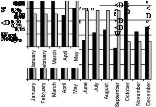
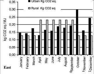
The results presented in the figure 3 support the idea that if we consider that all building design variables (orientation, materials, SOF, TOF, technology, etc) are maintained constant and only the location of buildings in the city are modify; the emissions related to the energy consumption vary
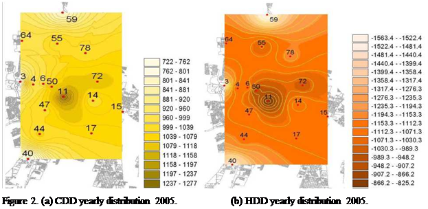 |
significantly too. It is especially during winter’s month. During winter the heat island effect results in minor energy consumption and, in consequence decreases the emissions generation. This could be thought as a beneficial effect, but it is important remember, that associated with this phenomena there are other environmental problems, as it was explained in the introduction.
4. Conclusions
Until now, in the study area, the values of HDD and CDD calculated for the bioclimatic zoning not have been taking into account the effect of the city’s configuration over the local climate. The results of this study show that, take into account the microclimatic effect produced by the city’s configuration is of particular importance, because within this area it is concentrated the greater building and demographic growth; and it represent the 70% of power demand of the province.
It is observed that the magnitude of the error committed when misestimating the effect of the city on the energy consumption, represents one underestimation of roughly a mean 9% of cooling requirements reaching values of 43% in december, while in the case of the heating period the values calculated exceed in as much a 50% of the real downtown’s demand. Almost, this demonstrates the importance of the urban morphology not only in the energy behavior of buildings but also in their environmental impact. At the same time, the problem is that a new building will modify the environment where it will be inserted; generating microclimate modifications. These modifications will affect at the same time the immediate environment of the building, and the whole microclimatic behavior of the city.
At this point the question is to know how the city’s growth must be planned in order to minimize the environmental impact. On the study area especially, since the 90’s, a disperse growth of the urban population towards peripheral areas is observed, resulting in a population growth of 2.2 % in the central area, while in the peripheral districts this value fluctuates between 26.16 and 40.09 %[6]. The changing value of the soil’s use is the result of the lack of governmental policies to preserve the balance of the activity systems and the oasis environment and the real-estate speculation, which is constantly motivated by the constant urban population growth, and consequently stimulating the tendency towards spatial urban expansion. The rapid increase in population in the last decade combined with the changing consumption patterns and life styles, are resulting in land and climate degradation of this arid environment. Therefore, quantifying the
 |
 |
microclimatic effects of urban design decisions implemented in a city is information of key importance to assess its energetic and environmental sustainability.
Figure 3. Kg of CO2 emitted by each additional MJ consumed for heating and cooling urban and rural areas
because the heat island effect.
References
[1] Sailor, D. J., Munoz, J. R. (1997) Sensitivity of electricity and natural gas consumption to climate in the USA — Methodology and results for eight states. Energy 22, 987-998.
[2] Correa, E. N (2006). Tesis Doctoral. Isla de Calor Urbana. El Caso del Area Metropolitana de Mendoza. Universidad Nacional de Salta. Facultad de Ciencias Exactas. Argentina.
[3] Akbari H., Davis S., Dorsano S. Huang J. And Winert S. (1992). “Cooling our Communities”. US Environmental Protection Agency, Office of Policy Analysis, Climate Change Division.
[4] Oke, T. R (2004). “Initial Guidance To Obtain Representative Meteorological Observations At Urban Sites”. Iom Report, Td In Press, World Meteorological Organization, Geneva.
[5] Erbs, D. G., Klein S. A. and Bechman W. A. (1983). “Estimation of degree days and ambient temperature data from monthly average temperatures”. ASHARE journal, 25 (6): 60-65.
[6] Alvarez, A (2000). “La Redefinition Territorial del Area Metropolitana de Mendoza en el Contexto de los actuates procesos de transformation”. Revista GeoNotas. Vol 4. N°4. Departamento de Geografia — Universidade Estadual de Maringa.
Architect/Department of Civil Engineering, School of Engineering & Technology
Cyprus University of Technology
Tel: 357-25002542, 25002724, Fax: 357-25002769,
Email: D. K.Serghides@cytanet. com. cy
Abstract
In previous research on energy efficiency in buildings has found that it is possible to achieve comfort conditions, for the Mediterranean climate, without the need for mechanical energy for heating and cooling in houses, through the use of compact shape and the optimization of insulation, internal mass and fenestration design.
However, it became clear in the work that a more sophisticated analysis of buildings and user behaviour was necessary and this forms the concern of this paper.
From building simulations and analysis of results in previous research on fenestration, it was found that the human element is instrumental in changing some of the assumed building characteristics by such simple acts as opening or closing shutters of doors and windows. It was also found that the effects of the behaviour of the building and the users must be considered interdependently as it is the combined effect that is important.
In this study, the relative thermal effects of the parameter of the use of shutters for shading, in various combinations in computer simulations, is to be considered to understand the qualitative behaviour of the building fabric in use. Also the possibility of introducing automatic shading controls is investigated. This leads to the optimal choice between different design alternatives based on flexibility, operational ease, and potential thermal efficiency.
As an integral part of the planning process, strategies are recommended which, by reducing the operational constraints currently imposed upon buildings, secure an optimized, performance for energy efficient houses in Mediterranean.
Keywords: Shading, shutters, human factor, energy efficient buildings
In previous studies on fenestration [1, 2-4] it has been concluded that the provision of shading devices is a very important fenestration parameter to combat overheating in the dwelling in the summer period.
It was also found that winter solar gains through fenestration reduce considerably (11%) fuel consumption for heating. The optimized fenestration shading strategies are summed up as follows:
Summer: Shading between 07.00-19.00 hours.
Winter: Unobstructed solar access between 07.00-17.00hrs
However the introduction of manually operating shutters in order to provide summer solar control in occupied (usual practice in Mediterranean) may result in large energy penalties when misused by the occupants in either season to cause:
In Summer : Overheating when the shutters are left open during the day.
In Winter: Solar losses by sun blinding when shutters are left closed.
In this chapter the misuse of shutters, in both seasons (winter and summer), and the effect on indoor temperature in free running buildings are examined through computer simulation with thermal analysis program “Quick” [2]. This is done in series of combinations of sun control on fenestration for the “Zero Energy House” derived in previous research [1].
This section presents and discusses the results obtained from building simulations of the “Zero Energy House” which have specific profiles of fenestration shading as their only variable and are modeled under free running conditions. The tested shading profiles are specified and outlined having as basis possible occupancy interference with the shading design objectives of the “Zero Energy House”. These may range from maximum solar admission to total exclusion of direct radiation as a source of heat, depending on the season (winter or summer). Thus the simulations of shading combinations are classified for the two seasons as follows:
A. Winter. In this series of simulations the effect of window shutters left closed during the day, contrary to the optimised fenestration winter strategy, and consequently the drop of indoor temperature is examined. The orientation of shaded windows is as follows:
a) All unshaded
b) North windows shaded
c) North and West windows shaded
d) North, West and half of South window area shaded
e) All Shaded
B. Summer. In this series of simulations the effect of window shutters, left open during the day, contrary to the optimised fenestration summer strategy, on indoor temperature rise is examined.
The orientation of windows left unshaded is as follows:
a) All Shaded
b) Half area South fenestration unshaded
c) All South windows unshaded
d) South and West windows unshaded
e) All Unshaded
The outline of window shading profiles of the building simulations and the effect on indoor temperature is tabulated in tables 1 and 2 and illustrated on figures 1-4. The discussion of the results follows the same order of the simulations as presented in the ranges for the two seasons as stated above (2. A. Winter and B. Summer). The calculations from each simulation is analyzed in terms of its own entity and invites remarks derived from comparisons with the calculations from simulations of the other shading profiles. All simulations are also analyzed on the basis of comparing results of each shading profile with the optimized design strategy for that range (All unshaded — for winter and All Shaded — for summer).
The performance of the parameters is analyzed in the following clauses and their efficiency is compared with each other and with the optimized strategy for the winter and summer season. The effect of the parameters on the indoor temperature as well as the deviation from comfort conditions are assessed both in winter and summer (tables 1, 2, figures 1-4). Particular shading patterns which appear problematic are identified in summaries for each season. Finally design strategies are recommended which by reducing the operational constraints of manually operated shading devices secure optimum performance of fenestration for the “Zero Energy House” in Cyprus.
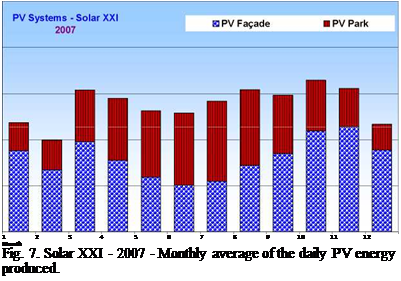
The energy production of both systems in 2006 is presented in Fig. 6, and for 2007 is presented in Fig. 7. For the year of 2006, the maximum daily average energy produced took place in August, 64.5 kWh, and the minimum occurred in November, 39.33 kWh. In 2007, the maximum was
65.7 kWh in October and the minimum was in 39.7 kWh in February.
|
 100
100
■£ 80
5
c
о
60
О
о.
>
О)
ф
с
ф
40
О)
го
ф
>
го
го
20 0
The yearly total energy produced by the PV systems, is depicted in Table 5 and Table 6, varying from 19.4 MWh in 2006 to 20.2 MWh in 2007.
|
Table 5. Yearly energy produced by Solar XXI PV systems, 2006
|
|
Table 6. Yearly energy produced on Solar XXI PV systems, 2007
|
Solar availability is quite high in Portugal, even during the heating season. This makes the direct capture of solar radiation (windows), the indirect collection for domestic hot water and space heating (thermal solar system) and eventually energy production (photovoltaics) advised. Large windows are mainly oriented south, increasing the useful solar gain during winter. Smaller areas are oriented east and west and minimal areas to north. Overhangs on south windows and exterior venetian blinds on all provide solar protection during summer.
High thermal inertia allows control over the inside temperature and combined with night ventilation, prevents overheating. In the bedrooms ventilation should take place in the evenings to avoid drafts during the sleeping period. In all other spaces, all night cooling can be used. High thermal inertia can be achieved by exposing the heavy concrete slab, using brick internal partitions
![]()
and preferably applying external insulation to the roof and walls. However, there is still some scepticism among Portuguese builders to the mechanical performance of exterior insulation. Therefore, this proposal uses the traditional double brick wall with cavity insulation.
Insulation levels proposed for the roof (150mm) and exterior walls (100mm) with U-values of 0.23 W/m2.K and 0.32 W/m2.K, respectively, are well below the current regulation requirements. Only a 1m stripe of the perimeter of the floor slab is insulated to allow the core of the house to release heat to the soil during summer. Windows facing south correspond to around 60% of the total glazed area and about 20% of glazed area faces east and another 20% west. Low-emission double glazing can be very effective in colder regions of Portugal, but in most situations standard double glazing is more cost-effective (U-values of 2.9 W/m2.K for standard double glazing and 1.9 W/m2.K for low-emission glazing are considered).
The utilization of solar panels for domestic hot water in new or refurbished buildings (a few exemptions apply) is compulsory under the new thermal regulation. The current proposal extends the solar installation to also cover a significant portion of the heating demand, by increasing the solar panels area and using a low-temperature hydraulic heat distribution (for instance radiant floor). The solar panels are installed facing south, tilted 50° from the horizontal plane, to increase the efficiency during winter. In accordance with the Passivhaus proposal, the active heating and cooling capacity is limited to 10 W/m2. The extra costs of the proposed Passivhaus for Portugal is 57 €/m2 with a payback period of 12 years.
Table 3 presents the electricity production obtained with TRNSYS for the three BIPV curtainwall constructions (scenarios 2, 3 and 4). As it can be observed, systems in Yellowknife and Iqaluit generate approximately the same amount of electricity, whereas the ones in Montreal produce between 4 and 7% less electricity. This can be explained by Yellowknife and Iqaluit greater annual south-facing vertical radiation and lower ambient temperature throughout the year. This table also indicates that scenario 4 is the worst in terms of electricity generation with a production reduced by more than 22% compared to scenarios 2 and 3. The building heating and cooling loads for each one of the 5 scenarios and 3 cities considered are shown in Fig. 6. From this graph, it can be seen that for every city, the lowest heating loads are obtained in scenarios where spandrel is used as the nonvision section, with a difference of only 2 to 3% between the double-glazed and triple-glazed cases (scenario 1 and 5). This variation is small considering that the triple-glazed curtainwall construction of scenario 5 has greater thermal resistance, but this assembly also has a lower solar heat gain coefficient and thus, provide less passive solar heating. The influence of changing from a double-glazed to a triple-glazed system on the space cooling energy requirements is only noticeable for Montreal, but is more important than for space heating with a difference between the two scenarios in the order of 6%. When comparing the substitution of spandrel panels with BIPV curtainwalls, it can be observed that it affects more significantly the space heating load than the cooling load, and the double-glazed systems than the triple-glazed systems. In fact, the heating load increases by 8.9-10.6% when going from scenario 1 to 2 and only by 4.6-5.3% and 5.6-6.3% when going from scenario 5 to 3 and 5 to 4, respectively.
|
Table 3. Annual DC electricity production for vertical curtainwall assemblies. # DC electricity production (kWh/m2 floor area)*
|
|
Scenario Fig. 6 Building heating and cooling loads for the 5 scenarios. |
2. Conclusion
This study showed that double-glazed and triple-glazed BIPV curtainwalls with a PV laminate used as the outer pane have similar electrical performance. When a PV laminate is used as the middle pane in a naturally ventilated triple-glazed fenestration system, however, a reduction in electricity generation in the order of 22% can be expected due to the smaller amount or radiation reaching the cells and the heating up of the PV. A possible benefit of this last configuration was found to be the reduction of perimeter heating in the winter caused by greater inner glazing temperature. In locations with important cooling load, however, this temperature could potentially create discomfort in the summer. When using BIPV curtainwalls for the non-vision sections of a southfacing curtainwall facade of a small office building, the heating load was found to increase by 8.910.6% for the double-glazed systems and 4.6-5.3% for the triple-glazed ones.
References
[1] M. M. Karteris, K. P. Papageorgiou, A. M. Papadopoulos, (2006). Integrated Photovoltaics as an Element of Building’s Envelope, Int. Workshop on Energy Performance and Env. Quality of Buildings, Greece.
[2] J. Ayoub, L. Dignard-Bailey, W., Richardson, (2003). Promoting Grid-Tied Solar Electricity on Buildings in Canada, SESCI 2003 Conference, August 18-20, Kingston, Ontario.
[3] J. Ayoub, (2006). National Survey Report of PV Power Applications in Canada, International Energy Agency Co-Operative Programme on Photovoltaic Power System.
[4] P. W. Wong, Y. Shimoda, M. Nonaka, M. Inoue, M. Mizuno, (2008). Semi-Transparent PV: Thermal Performance, Power Generation, Daylight Modelling and Energy Saving Potential in a Residential Application, Renewable Energy, 33, 1024-1036.
[5] T. Fung, H. Yang, (2008). Study on Thermal Performance of Semi-Transparent Building-Integrated Photovoltaic Glazings, Energy and Buildings, 40, 341-350.
[6] D. Curcija, W. P. Goss, (1995). New Correlations for Convective Heat Transfer Coefficient on Indoor Fenestration Surfaces — Compilation of More Recent Work, ASHRAE/DOE/BTECC Conference, Thermal Performance of the Exterior Envelopes of Buildings VI.
[7] R. J. Cole, N. S. Sturrock, (1977). The Convective Heat Exchange at the External Surface of Buildings, Building and Environment, 12, 207-214.
[8] J. L. Wright, (1996). A Correlation to Quantify Convective Heat Transfer between Vertical Window Glazings, ASHRAE Transactions, 102, Pt. 1, 940-946.
[9] ASHRAE, (1998). Standard Method for Determining and Expressing the Heat Transfer and Total Optical Properties of Fenestration Products, Public Review Draft of Standard 142P, American Society of Hating, Refrigerating and Air Conditioning Engineers, Atlanta.
[10] Y. Poissant, L. Couture, L. Dignard-Bailey, D. Thevenard, P. Cusack, H. Oberholzer, (2003). Simple Test Methods for Evaluating the Energy Ratings of PV Modules Under Various Environmental Conditions, Proc. 2003 ISES Solar World Congress, Junte 14-19, Goteborg, Sweden.
[11] SEL (Solar Energy Laboratory), (2005). TRNSYS 16 — A Transient System Simulation Program, University of Wisconsin, Madison, Wisconsin.
[12] D. E. Holte, (1995). A Parametric Study of the Impact of High Performance Windows (and Curtain Walls) on Building Heating and Cooling Loads, Energy Use & HVAC System Design, Conf. Proc. Window Innovation’95 Toronto, Canada, June 5-6, 500-508.
[13] Enermodal, (2001). FRAMETMplus 5.0 developed for Natural Resources Canada.
[14] Natural Resources Canada, (2005). RETScreen Int. 4.0 — Clean Energy Project Analysis Software.
[15] Caneta Research Inc, (2001). Development of Generic Office Building Energy Measures, Report prepared for Public Works and Government Services Canada.
[16] National Research Council Canada, (1997). Canadian Model National Energy Code for Buildings 1997.
Nomenclature
|
Symbols |
cv |
Convective |
|
|
Specific heat at constant pressure (kJ/kgK) |
g |
Glazing |
|
|
c |
Specific heat at constant volume (kJ/kgK) |
gnd |
Ground |
|
F |
View factor (dimensionless) 2 |
i |
Inner |
|
h |
Heat transfer coefficient (kJ/hm2K) |
in |
Inlet |
|
H |
Window height (m) |
Li |
PV laminate glazing facing indoor |
|
m |
Mass flow (kg/h) |
Lm |
PV laminate middle layer (PV+EVA) |
|
Ppy |
PV cells power (kJ/hm2) |
Lo |
PV laminate glazing facing outdoor |
|
R |
Thermal Resistance (hm2K/kJ) |
o |
Outer |
|
t |
Thickness (m) |
out |
Outlet |
|
T |
Temperature (K) |
rd |
Radiative |
|
S |
Absorbed solar energy (kJ/hm2) |
sky |
Sky |
|
W |
Window width (m) |
sur |
Surroundings |
|
Subscripts |
Greek symbols |
||
|
a |
Air cavity |
є |
Emissivity (dimensionless) |
|
amb |
Ambient |
P |
Density (kg/m3) |
|
cd |
Conductive |
a |
Stefan-Boltzmann constant (kJ/hm2K) |
In order to extend the evaluation from ecological to economical aspects, investments and running costs (cleaning, energy, maintenance etc.) have to be considered as well. The evaluation system offers an EXCEL tool for calculating cost indices according to the morphological box, based on costs of fa? ade components. For purposes of overall judgement the cost indeces can be transformed to marks comparable to the energetical indices.
Finally the separate energetic and economic evalutions can be combined to a comprehensive judgement by the user. For the different aspects of the evaluation relative weights have to be determined by the user. This allows him to stress certain criteria in an individual manner for a certain purpose. A building investor, e. g., will have preferences differing from those of a building owner who intends to occupy the building.
|
1st International Congress on Heating, Cooling, and Buildings — 7th to 10th October, Lisbon — Portugal /
Fig. 4. Comprehensive evaluation of three fagade systems 3. Additional Applications of Energy Assessmant, Outlook |
Currently the eveluation system is an EXCEL tool by which fagade parameters can be classified only stepwise within certain bandwidths. The next target is to develop a tool, which allows a stepless, continuous definition of input parameters. First tests have proved that the output of energetical data can be derived by a five dimensional intepolation tool. There was developed a free choice of interpolation for properties by regession analysis. Thus an unbounded design variety can be evaluated quickly, based on a limited number of elaborate simulations.
The assessment system was initially developed for an application by clients in early design stages. During the process of development there has been discovered a large potential of additional applications. The assessment method might be used by designers and consultants as well in early and advanced design stages for purposes of control and/or optimazation of certain aspects.
The Diploma thesis of Preibler [2] gives an example for the advanced energetical analysis of fagade systems. One objective was to visualize the influence of the five physical design parameters on the energy demand. Three dimensional diagrammes (Fig. 5) and vector-analysis can help to catch the influence on one glance.
Another application of the assessment tool might be to generate facade designs under given boundary conditions. More research is necessary to gain the full potential of energy assessment systems for an improvement of the design process.
|
A
Parameter 1 Fig. 5. Total primary energy demand for a given variation of parameters |
References
[1] Gralla, Mike, Muller, Helmut: Unpublished research report for Bundesamt fuer Bauordnung; „Bewertung von Glasfassaden unter Berucksichtigung von Kriterien der Enrgieeinsparung und Wirtshaftlichkeit“, (2008)
[2] Preissler, Andreas: Diploma thesis “Einfluss von Fassadenparametern auf den Gesamtenergiebedarf von Gebauden”, Lehrstuhl Klimagerechte Architektur, TU Dortmund, (07/2008)
The Health Sector has a large glazed area facing the North that collects direct solar radiation in winter. The hourly sunlight projection on the wall of the North corridor entering through a window of the Health Sector, is shown in Fig. 4 for a winter day. The projection was calculated through the

 |
software LuzSol [5], developed at Universidade Federal de Sao Carlos, Brasil. The openings are 2m width and 1m high. Because solar radiation reaches the half bottom of the wall most of the day, a dark colour painting is Fig. 4. Sunlight projection on a North wall recommended to increase the absorbed solar energy in of a window in the Health Sector (winter). winter.
![]() (a)
(a)
Fig. 5. Hourly thermal behaviour of the Health Sector in typical winter day. (a) North and central thermal
zones; (b) South thermal zones.
The hourly thermal behaviour of the Health Sector is shown in Figs. 5 (a) and (b) for the North, central and South thermal zones. For a mean outdoor temperature of 10.7°C, the North corridor reaches a mean temperature of 15°C, with a maximum of 19 °C at 14PM (solar hour). The mean temperatures of the central offices are around 13°C, requiring small conventional air heaters to reach the comfort zone. The thermal swings are 8°C in the North corridor and 6°C in the offices. All zones facing South will require auxiliary heating (Fig. 5b). Only in clear sky days, when the solar irradiance reaches 10.6MJ/m2, the offices will not require auxiliary heating (Fig. 6a). A possibility to heat the central offices would be the use of the North corridor as a sunspace from which the hot air could be introduced by natural convection into the offices through little openings in the wall, that should be mechanically closed during the night.
This strategy was evaluated by the simulation of the building in a clear sky day. Two openings were considered in each office, one at floor level and the other at 2m height, near the ceiling. The openings sizes were 0.75m x 1m, that is, a 1% of the office wall area. When the vents are open (Figure 6b), the air temperature of the corridor and the offices are 1 °C lower and 1°C higher, respectively, than in Fig. 6a. Because the temperature in the corridor is still high, extract fans could be added to remove the air of the corridor and blow it within the doctors offices.
(a) (b)
Fig. 7 Hourly outdoor temperature, solar irradiance on horizontal surface (W/m2) and hourly temperature of
the thermal zones in the Development Sector for a winter day. a) Original design, b) an additional roof
clerestory.
In those days when the solar radiation approaches the monthly daily average value (7.93 MJ/m2), it will be necessary auxiliary heating because the direct solar gains are not sufficient to reach the thermal comfort. For any solar radiation value, southern rooms always require auxiliary heating.
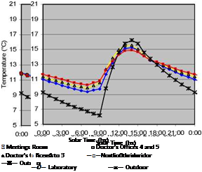
The Development Sector needs auxiliary heating during the winter, because the solar heat gain is mostly collected only on East windows (the West windows are shaded by the surrounding buildings). Figure 7a shows the hourly thermal behaviour of this Sector: when the mean outdoor temperature is 10.7 °С, the mean indoor air temperatures are around 11.7 °C with thermal swings of 5°C. Between 10:00AM and 16:00PM, the outdoor air temperature is higher than indoors, and the maximum temperature is reached at 14:00PM. The office of the social assistant is the warmest
local because it is small and it collects direct solar gain, whereas the more cold local is the storeroom, that does not have direct solar gain. To reduce the auxiliary heat load in winter, two options were tested: an increase of the solar collection through clerestories in the roof, and a lowering of the thermal losses through the roof. The simulation of the first option, that is, the addition of glazed areas facing North in the roof showed no significant increase of the indoor air temperatures. The second tested option was the addition of a tight air chamber in the roof (with ventilation in summer), between the metal sheet and the thermal insulation. The results are shown in Figure 7b: in this case, with an outdoor mean temperature of 10.7°C, the indoor mean temperature is around 12.7 °С. Also it was observed that diurnal temperatures of several rooms increased behind the outdoor temperature. A greater indoor thermal amplitude is not a problem since the thermal behaviour of the building was significantly improved during the occupation hours. For example, the daily thermal amplitude of the classrooms is 9 °С, but during the occupancy period (8 AM to 20PM) it is around 5°C and the mean temperature is 15°C.