Как выбрать гостиницу для кошек
14 декабря, 2021
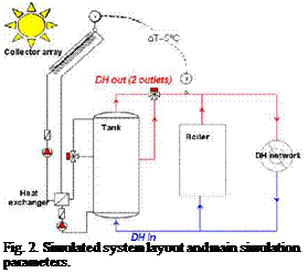
There are several possible ways to connect a solar thermal plant to a DH network, with no proven general optimal system layout. The chosen system design principle is shown in fig 2., where the storage tank is connected in parallel with boilers. The control system keeps the outlet temperature from the collector array always above the required DH supply temperature by varying the collector loop mass flow rate. This control strategy is needed, if one wants to be able to completely turn off the boilers for a period during summer.
The main sizing criteria was to be able to turn off boiler(s) for some period during the summer, as this would both save maintenance costs and reduce boiler operation at low efficiency. This requires a solar fraction of around 90-95% during June-July. It should be mentioned that this is not the optimal case for the solar thermal plant as high solar fractions result in lower specific collector yields, mostly because of higher collector temperatures and the fact that the storage tank is more often fully charged. It was also decided that for simplicity boiler operation would not be considered in the storage tank sizing. The benefits of having a storage tank available for a boiler are too difficult to convert to economical benefits in a generalized manner, and can only be considered case to case when sizing a plant.
Collector
 По (-) 0.8
a1 (W/m2K) 1.76
a2 (W/m2K2) 0.0323
A total (m2) 13.52
Aaperture (m ) 12 5
Storage tank
h/D ratio (-) 2.5
lave, internal (W/mK) 0.8
Insulation thickness (m) 0.3
DH flow temperatures
Tsupply/Treturn winter (°С) 90/50
Tsuppiy/Treturn summer (°С) 65/40
Tamb at sizing point (°С) -30
The scenario is that solar panel array and heat storage tank are added to an existing DH-plant. The panel array and storage tank are ground mounted. Expected main financial savings: fuel, maintenance and electricity. Cost functions for the investment, running costs and savings were based on earlier studies, reported costs from realized plants and budget prices from manufacturers. The NPV calculations were done and the results presented in a manner that tries to answer the question “Under which scenarios would it be feasible?” rather than more traditional case studies, where the feasibility for only a few scenarios are calculated and for which a sensitivity analysis is done. In the presented graphs a shortest feasible payback period for a scenario is found where the curve crosses the x-axis.
The useful lifetime of a solar thermal plant is estimated to be 20-30 years. No subsidies are considered in the calculations. At the time of the study, energy prices for large scale consumers were as in table 1. The calculated electricity savings were so small that changes in electricity price had insignificant effect on feasibility.
|
Table 1. Used energy prices.
|
It must be noted here that economic viability is up to the investor to decide, keeping in mind that different actors within the heat service business may have different decision criteria depending on company size and long term strategy. Therefore only comments on whether a feasible payback period can be found within the lifetime of the plant are given here.