Как выбрать гостиницу для кошек
14 декабря, 2021
Transient shading of the outer module (left module in Fig. 1) by the edge of the roof or wall starts in the morning earlier at the solar angle — mE <-mF. Correspondingly, it expires later in the evening. Duration of the transient screening in angle units corresponds to Eq. (5), while we exchange the distance between the modules to the distance from the edge of the basis DR^DC. The module is completely illuminated, when the sun reaches the position described by the clock angle mF, while the sun shines along the virtual envelope plane.
An outer module performs close to the stand-alone module once per day, while it performs like an inner module for the second time. Duration of the transient screening of the outer module in Fig. 6 is less than such for the inner one.
 |
 |
Available minimum value of the distance DC min=WC (cos%)/2, when the edges of the basis and the module touch. In this case =x and there is no transient shading effect. If a module should be installed at an infinitive long distance from the edge of the fa$ade, then DC and the duration of the transient screening aspires to zero.
 |
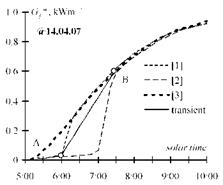
A “PV-module” is modeled with two pyranometers, installed on the outer (“1” & “4”) and inner edges (“2” & “5”) of a plywood sheet (Fig. 7). We use two of such “modules” instead of rotating and commutate the outputs at the moment of “rotating”. Neighboring modules, which screen the beam component of radiation, are the pure plywood sheets installed at a certain distance and with the corresponding deflection angle. Pyranometers “3” and “6” are installed above the “farm” and perform like a stand-alone module with a two-positional tracking. They are used for the experimental control of the limited gain. Figure 7 shows a “farm” with the vertical position, but the same was used to control the “farm” with the tilted (p0=45°) position. The diagram in Fig. 8 shows a recorded transient shading process in the sunny morning on 14 April 2007. The dashed lines are irradiances measured by pyranometers 1, 2 and 3, correspondingly. Lines have finite slopes due to the finite area (25 cm2) of the used pyranometers. The points highlighted correspond to the start of transient screening (point A) and its finish (point B).
 |
 |
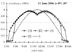
The diagram in Fig. 9 shows the recorded irradiance for an inner module exposed with the two — positional tracking while the deflection angle is x =30°. the tilted p0 =45° “farm” was installed due south y0=0 using the relative distance dR = 2. Positions of sensors correspond to Fig. 7. The line without marks shows the irradiance for the stand-alone fixed module at p0 = 45° due south.
Fig. 8. Measured transient shading process for Fig. 9. Recorded irradiance for the module with two-
the stand-alone [3] and the inner module of the positional tracking inside a “farm” while deflection
“farm” [1, 2]. angle is 30° and relative distance dR =2.