Как выбрать гостиницу для кошек
14 декабря, 2021
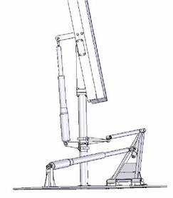
The azimuthal tracking system with linear actuators developed on the platform of Transilvania University of Bra§ov is presented in fig. 3. Panel 1 is assembled on a frame made of L profiles 2 mounted along the panel welded together with the central beam 3. The seasonal rotational axis is created by the rotational link 9 between the central beam 3 and the parts mounted on the beam 10 attached to the leg. The seasonal movement (with angle a) is performed with the screw linear actuator 11, attached to bushing 4, through lever 13, on one side and on lever 12 attached to central beam 3, on the other side.
|
|
|
|
 In order to accomplish the azimuthal (daily) movement, the pillar is built from two sub-assemblies. The leg 5 and the tube 14 (fig. 4), attached together by the pin 17, are fixed on the support structure 6. Tube 4 and central beam support 10, assembled with screws, can rotate towards the other sub-assembly. The azimuthal movement is driven by the screw linear actuator 8 acting on element 7 of a spatial mechanism.
The bearing mounting of the rotating parts 10 and 4 relative to the fixed parts 14 and 5, is taking axial forces at one side, leaving the other side for taking possible thermal displacements. The ball bearing 15, mounted with a bearing nut 16 can take axial forces in both directions. The pin bearing 18 allows thermal expansion of parts, coming from themperature differences of seasons.
Figure 5 presents a longitudinal section through the bearings of the seasonal rotational axis. Double sealed ball bearings are used for this rotational axis. The journal part 19, on which the inner ring of the bearing is mounted, is assembled on the central beam 3. The cap 20, on which the outer ring of the bearing is mounted, is assembled with screws on the central beam support 10, which is made of a square profile. The axial force on this bearing mounting is transmitted from the exterior of the inner ring to the interior of the outer ring, as it can be seen from the diagram from fig. 5.
 |
 |
Figure 6 presents the extreme positions of the panel, corresponding to loading cases: a — for a = 67°, summer solstice at noon; b — for a = 9°, winter solstice at sunrise.
Fig. 6. Extreme positions