Как выбрать гостиницу для кошек
14 декабря, 2021
The simulation model of the installation will be used in future to perform online simulations in order to detect some potential errors/malfunctions of the system and alert the users. This process has to be automated in order to simulate at the end of each day the installation and compare the results with the measurements.
Additionally, the model will be used to study the possibility of varying the cycle of the adsorption chillers when the cooling demand of the building is not so high, in order to increase the COP and reduce the input heat in the chillers. Furthermore, the control strategy of turning on the 3 chillers according to the cooling demand will also be investigated.
This paper shows the results of dynamic simulations of a large solar adsorption cooling plant installed in the company FESTO AG nearby Stuttgart in Germany. Even if some works are still required to enhance the quality of the model, the results show an acceptable agreement between simulated values and measured ones. This simulation model will be used in future to perform online simulations for an automated alarm and fault detection system. The adsorption chiller model will be also used to study the effect of the variation of the cycle time of the chiller and to optimize the control strategy of turning on the 3 adsorption chillers (when should they be turned on).
 |
 |
This work would not have been possible without the collaboration of the company FESTO AG and the University of Applied Sciences Offenburg who have provided all the measurement data necessary for this study. This work has been supported by the 6th European Union Research Program’s Marie-Curie early stage research training network in “Advanced solar heating and cooling for buildings” — SOLNET. http://cms. uni-kassel. de/index. php? id=2142
[1] Huber, K. “Detailmonitoring einer solarthermischen Anlage zur Unterstutzung des Kalteversorgung eines Buro — und Verwaltungsgebaudes”, 18. Symposium Thermische Solarenergie Staffelstein, 2008.
[2] Schumacher, J. “Digitale Simulation regenerativer elektrischer Energieversorgungssysteme”, Dissertation Universitat Oldenburg, 1991 www. insel. eu
[3] Dalibard, A., Pietruschka, D., Eicker. “Performance analysis and optimisation through system simulations of renewable driven adsorption chillers“. 2nd SAC, Tarragona, Spain, 2007.
[4] University of Applied Sciences Offenburg. Internal meeting project (July 2008)
[5] Saha, B. B. et al.: “Computer simulation of a silica gel-water adsorption refrigeration cycle—the influence of operating conditions of cooling output and COP”ASHRAE Transactions 13 (6) (1995) 348355.
[6] K. C. Ng, H. T. Chua, C. Y. Chung, C. H. Loke, T. Kashiwagi, A. Akisawa, B. B. Saha. “Experimental investigation of the silica gel-water adsorption isotherm characteristics”, Applied Thermal Engineering, Volume 21, Issue 16, 2001, 1631-1642.
Simulations discussed above were repeated for Melbourne and Darwin climates. Mean monthly climate profiles for each of the three cities [8] are illustrated in Figure 6. Melbourne is a warm temperate climate, similar to Sydney, but with a colder winter and colder nights. Darwin is a tropical climate with wet and dry season differences dramatically influencing cloud cover.
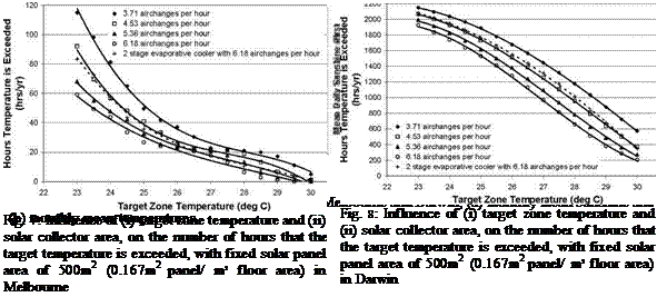 |
The impact of air flowrate on the frequency of high zone temperature events for the Melbourne and Darwin climates is illustrated in Figures 7 and 8 respectively
Figure 7 suggests that zone temperatures can be maintained below 26°C for all but 20 hours per year without the use of any backup fossil fuel heat source. It appears that the stand-alone solar desiccant cooling process can potentially provide an acceptable comfort airconditioning solution in the Melbourne climate.
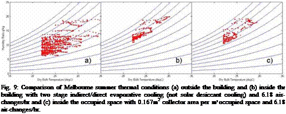 |
The viability of the two processes (solar cooled and two stage evaporative cooled) in Melbourne is further illustrated in Figure 9, by plotting the simulated temperature and humidity in the occupied space at each half hour interval where temperature exceeds 22°C.
In Melbourne, the less complex evaporative cooling process achieves much of the same benefit as the solar desiccant cooling process. However, the solar desiccant step reduces the number of hours where temperature is above traditional airconditioning set-point temperatures (~23°C) and reduces humidity levels in the occupied space by around 5.5%
In contrast to the Melbourne climate, Figure 8 suggests that high temperature events can not be adequately prevented in Darwin by the stand-alone solar desiccant cooling process. Evaporative cooling appears to provide only limited assistance to the solar desiccant cooling process in the tropical Darwin climate. This is understandable because outdoor air starts off significantly warmer and more humid. Consequently, evaporative cooling is less able to achieve low temperatures consistent with desirable indoor air conditions.
|
Figure 10 illustrates the impact of target zone temperature and collector area on the number of hours per year that the zone temperature exceeds the target in Darwin.
Target Zone Temperature (deg C) |
Fig. 10: Influence of (i) target zone temperature and (ii) solar collector area, on the number of hours that the target temperature is exceeded in Darwin, with fixed desiccant cooled air flow of 3.71 airchanges per hour.
It is apparent that the addition of extra collector area will not easily produce acceptable comfort conditions in Darwin using the solar desiccant cooling process as described in Figure 1.
Alternative cycles/ component arrangements may need to be considered for tropical climates.
The hour by hour performance of a standalone, once-through desiccant cooling system for airconditioning a commercial office space, was examined using the TRNSYS computer simulation software. The study particularly focuses on the potential for designing and operating a desiccant cooling system without any thermal backup provided to mitigate for intermittent solar availability.
The study investigated the impact of manipulating (i) indirect evaporative cooler effectiveness, (ii) desiccant cooled air flow to the office space, and (iii) solar collector area, on the comfort conditions experienced in the office space. Differences between the performance of the solar desiccant cooling system in (i) the warm temperate climates of Melbourne and Sydney and (ii) the tropical climate of Darwin were also investigated.
When low humidity air is available, the effectiveness of the indirect evaporative cooler heat exchanger was shown to have a marked impact on the achievable temperature drop. Increasing collector area and air flowrate to the occupied space, were both shown to reduce the frequency of high temperature events in the occupied space. In the warm temperate climate of Melbourne (and to a lesser extent Sydney), high ventilation rates enabled comfort conditions to be maintained at or near acceptable levels in the occupied space, with-out the use of a backup thermal source. During extreme weather conditions, evaporative cooling appears to be the dominant mechanism for cooling the occupied space.
This synergy between evaporative cooling and solar desiccant cooling, observed in the warm
temperate climates, was not evident in the tropical Darwin climate. Further research is required to
model alternative cycles with more promise in tropical climates.
П Solar collector efficiency
T Collector fluid inlet temperature (°С)
Tamb Ambient temperature (°С)
G Solar insolation (W/m2)
[1] White S. D., Kohlenbach P., and Bongs C., “Desiccant cooling system modelling and optimisation”, International Sorption Heat Pump Conference, Seoul, Korea, September 2008, in press
[2] Lam J. C., Hui S. C.M., and Chan A. L.S., “Regression analysis of high rise fully air-conditioned office buildings”, Energy and Buildings, 26, 1997, 189-197
[3] Beccali, M., Butera, F., Guanella, R., and Adhikari, R., “Simplified models for the performance evaluation of desiccant wheel dehumidification”, International Journal of Energy Research, 27, 2003, 17-19.
[4] TRNSYS v16.x TESS Libraries Version 2.0, Thermal Energy Systems Specialists, LLC, Madison, WI
[5] LTS-Collector Catalogue 2002, Institute fur Solartechnik SPF Rapperswil. BFE Bundersamt fur Energie, Bern, Switzerland
[6] H.-M. Henning, Solar Airconditioning and Refrigeration, Task 38 of the IEA Solar Heating and Cooling Programme, presentation to Sustainability Victoria, May, (2007)
[7] 2008 ASHrAe Handbook, HVAC Systems and Equipment, pgs 40.2-3
[8] Australian Bureau of Meteorology, http://www. bom. gov. au/climate/averages/
On-off Control
This kind of control is based on the comparison of two different signals: one is the variable we want to control Ts and the other is the setpoint we want to obtain Ti. It is evaluated the difference between them and in function of the value of this error is calculated the output. If it is in stop state, the output is not set to 1 until is reached a value of the difference higher than ATa. If it’s running and the error begins to decrease, it does not stop till this error reaches a value ATp. With this kind of control, is possible to reduce the number of oscillations of the system.
Control by means of PI (Proportional-Integral).
Once they have been established the conditions to start up the installation, using any of the previous strategies, the setpoint value can be sent to the pump, in which case there can be an on-off control system or on the other hand there can be a controller which receives the start signal and that varies the pump flow in order to maintain the temperature setpoints.
Although there are a huge amount of theories about the adjust of the parameters of the controller, note that the fine-tuning has been made in this case by means of trial and error, and so the values introduced on the system are the best of all obtained.
The PI controller has been used for the variable flow regulation of the pumps as well as for the three way valve if necessary (depends on the case).
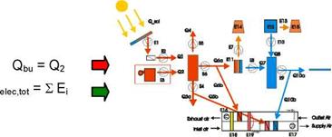 |
The first level of the procedure permits to acquire basic information on cost and performance (on primary energy level) of the system with a limited number of sensors. Within this level 4 heat flow meters and the electricity counters for the measurement of the electricity consumption of the overall system is required. In Figure 3 the scheme with the measured energy fluxes is shown.
Figure 3. 1st level monitoring scheme including measured inputs and outputs of the solar assisted cooling
system
The primary energy ratio of the solar assisted cooling system can be calculated as shown in (Equation 1:
Where the heat and electricity fluxes are measured while the primary energy conversion factors for heat and electricity from fossil fuels have been set with the following values, being based on European Directives [4], Task 25 and Task 32 [7]:
• seiec = 0.4 (kWh of electricity per kWh of primary energy)
• sfossil = 0.9 (kWh of heat per kWh of primary energy)
• nboiler = 0.95 (boiler efficiency)
In general it has to been stated that the conversion and performance factors given in the present paper are based on literature and discussion agreements but have to be considered only as proposals for calculation and comparison as they depend on different aspects such us country specifications, technology and component size. The Primary Energy Ratio of a reference system (see Figure 2) can be calculated as shown in (Equation 2:
In this equation the heat and electricity fluxes are again the measured values. Within the calculation of the electricity consumption of the reference system the consumption of the pumps of solar circuit loop and of the absorption chiller have to be subtracted according to Figure 2 and as shown in (Equation 3.
![]() Eelec, tot _ ref = Eelec, tot — (E1 + E2 + E6 + E7 + E8 + E10 + E11 + E14 + E18 + E1q)
Eelec, tot _ ref = Eelec, tot — (E1 + E2 + E6 + E7 + E8 + E10 + E11 + E14 + E18 + E1q)
The electricity consumption of the auxiliary E3 has to be corrected as described with (Equation 15, since the auxiliary in the reference has to deliver much more heat. The primary energy conversion factors for heat and electricity from fossil fuels have been listed before, the Seasonal Performance Factor (SPF) of the reference compression chiller has been set to:
• SPFref = 2.8 (compression chiller efficiency of the reference system)
• nboiler, ref = 0.95 (reference boiler efficiency)
From the financial point of view the overall cost per installed cooling capacity can be calculated following
Cost (€) includes the costs of all components shown in Figure 1 minus the appliances deployed in the corresponding conventional reference system (Figure 2) such us back up heating / cooling system and eventually installed cogeneration systems.
2.1. Second level
 |
The second step consists within deeper partial monitoring of single parts of the system with an increased number of sensors in respect to the 1st level. In fact within this level 2 heat counters and a pyranometer have to be added to the 4 heat counters and the total electricity counters already present in the 1st level. The monitoring for this level is concentrating mainly on the solar thermal energy management (see Figure 4).
In the following several equations are shown which allow to calculate the amount of solar energy which the solar assisted cooling system is not able to exploit because of different losses such us within the solar collectors, heat exchangers or the storage.
The amount of solar energy that is not exploited because of losses in the solar loop, heat exchangers and collectors is calculated by the (Equation 5 — (Equation 6:
|
Vcott. net _ Q Qsol |
(Equation 5) |
|
^Qsol _ Qsol (1 — Vcoll ) |
(Equation 6) |
|
The amount of thermal energy that is not exploited because of losses in the storage the (Equation 7 — (Equation 8: |
is calculated by |
|
n _ Q3 + Q6 + Q4 иГа*Є Q1+Q2 |
(Equation 7) |
|
Qloss, storage _ (Q1 + Q2) — (Q3 + Q6 + Q4) |
(Equation 8) |
|
Finally, the amount of available solar energy that is not used in the thermal loop of the solar |
|
|
assisted cooling system (Qsolar, unex) is calculated by the (Equation 9 — (Equation 13: |
|
|
SF _ Q (Q, +Q2) |
(Equation 9) |
|
Q* _ SF • Q6 Q3* _… |
(Equation 10) |
|
Q* _ Q* + Q* + Q* |
(Equation 11) |
|
Qo — Q* |
|
|
|
|
|
|

The third level consists in a full system monitoring based on the method of “fractional energy saving” as part of the FSC method which was elaborated in the IEA SHC Task 26 for solar combi systems and extended in the IEA SHC Task 32 for solar heating and cooling systems [7]. This file outlines the energy-flux components required to characterize the performance of solar heating and cooling systems with this method. The FSC method as such is not explained in this document, readers interested in a tutorial on the FSC method are referred to the cited literature [8] [9] [10].
 |
|
|
|
|
|

(Equation 14 defines the “fractional solar heating & cooling savings” (f savshc) in terms of:
• energy consumption attributed to auxiliary devices required for the solar heating/cooling system. (numerator)
• energy usage allocated to a reference system with no solar energy-input (denominator)
The crux of the mater is to come up with a practical definition as to define the reference system, having in mind that the only accessible measurement object is the building with the SHC system. The proposed strategy is to derive the electricity consumption of the reference system “Eel, ref” from the SHC system, by adequate modifications in the measurement data analysis, following the below outlined scheme:
• define a maximal equipped SHC system (see Figure 1, labelled “SHC_max system”)
• the appliances deployed in the corresponding conventional reference system are depicted graphically in Figure 2 by skipping all solar assisted equipment from the SHC_max system.
• All thermal and electrical energies of the conventional reference system can be determined from measurements conducted in the SHC_max system using the following assumptions.
• All thermal energies (hot/cold) supplied by solar in the SHC-system are fully substituted by conventional heat/cold production in the reference system.
• Electricity consumption of pumps for DHW+SH and cold supply is equivalent in the SHC — systems and the reference systems.
For the measured solar heating and cooling system (numerator in (Equation 14) the energies according to Figure 1 are as following: The measured boiler energy supplied to the system Qboiler is equal to Q2 and the additional cooling provided from the compression chiller Qc0oiing, m[ssed is equal to Q8. The electricity consumption Eel is the sum of all electricity consumer except the compression chiller: Eel = (£ Ei)-E10-E12-E13-E15.
For the reference system (denominator in (Equation 14) the following calculations have to be done:
For the boiler the ratio of electrical energy to thermal energy is identical in the SHC-system and the reference-system.
Reference storage heat losses according to IEA SHC Task 26 and with reference to ENV 12977-1 (2000):
Qlossref… Reference storage heat losses [kWh/a]
VD.. .Average daily hot water consumption [Liter/day]
TT.. .Set point temperature of the hot water tank [°С], 52.5°C is used for this
in Task 26
Ta. Ambient temp. around the hot water tank [°С], 15°С is used for this in
Task 26
The reference boiler energy supplied to the system therefore is:
Qboiler, ref = Q SHc(Q3) + QsDHcw (Q4) + Qf (Equation 17)
On inspection of Figure 2 the electrical energy consumption in the ref. system sums up to:
Er1f = E DfW, el(E5) + Ef (E4) + Ercrfsupply (E9) + E^”1" + E^ (Equation 18)
|
Eel, boiler ref * aS |
|
= asHc * (QSHc(Q3) + QDHw (Q4) + Qross) |
Where the electrical consumption of the boiler in the reference system is given through:
Fans’ electricity consumption for the conventional ventilation system is calculated based on the measured electricity consumption of the desiccant cooling system (SHC_max,) and corrected by the ratio of theoretical design pressure losses of the conventional ventilation system to the desiccant cooling system (based on datasheet of the DEC system). The electrical consumption of the two fans of the ventilation system can be estimated by:
Б™пРє1 = E™^1 • f (APREF, APdec ) (Equation 20)
Considering that for each fan of the system, the electrical power is given by (with V in [m3/s] and AP in [Pa]):
 AP • V
EFan =——- W ]
Assuming the same n and flow rates for the fans of the reference and DEC system, the electricity power of the reference system can be calculated as following:
All the AP are known for the DEC system. The AP for the reference Air Handling Unit (AHU) can be estimated considering in the calculation only the components used, assuming that normally the pressure losses of each component of the DEC Air Handling Unit are known from the manufacturer of the AHU.
|
+ (E16 + E17) * f (AP) |
 |
|
These calculations result in the definition of the electrical consumption of the reference system in terms of data measured in the SHC-system:
Qcooling, ref = Q cHC= 6acm(Q7) + 6bup(Q8) + Qdec — Q10b 25)
Where QDEC is: Thermal cooling energy delivered from DEC system in the SHC-system in terms of enthalpy difference between ambient air and supply air (latent and sensible heat has to be taken into account!)
The Seasonal Performance Factor SPF for the compression chiller in the reference system can not be known exactly. The following possibilities are proposed:
• SPFmeas measured SPF in the monitored SHC system
• SPFref proposed SPF for a chiller in the reference system: SPFref = 2.8
3. Expected results
The target from the presented monitoring procedure is to have a common base for the monitoring of solar assisted heating and cooling systems, allowing a comparison of the performance of different systems and allowing the elaboration of a learning curve of the following years.
The developing process has comprised design and production of process equipment and processing forms for paddle vanes and turbine casing as well as internal heat exchangers.
Although there are substantial technological challenges to be solved related to the design, construction and test of the proto type, the primary challenge is to end up with a system that is commercially competitive.
Design and construction of prototype
The design of the turbines together with the bearing systems was fulfilled at the end of February. The conceptual design gave adequate data to produce the 4 different turbine parts and further design of the turbine house, the bearing system, the spindle etc. all to manage high speed on the spindles.
The turbine parts were delivered in the start of April and installed together with the external components (evaporator, condensers, fans etc.). The turbine sealings/washers were later changed to manage adequate higher temperatures.
Through the sampling of the parts several changes were made e. g on the sealing on the connections between external parts for keeping a specific vacuum in the pipelines.
Testing
The external cooling and heating components have been designed, produced and mounted/installed for test purpose e. g. prepared for vacuum, setting up for optimal measurement of temperature, pressure etc.
Furthermore a PC and a data logger has been installed to make the measurement on different temperatures and pressures around the turbines and external components. The RPM-counter uses light to measure the speed — the power used to heat the water (in stead of a solar collector) is measured; PC- programs to calculate the performance on the proto type using test data (temp., pressure, RPM, power) are completed.
Test series on the proto type are going on in august 2008. Report on the test results will firstly be available on www. ac-sun. com.
Newest: Logged data from the first tests on the proto type gives positive results and confirms the function in the design. The expander delivers the compressor capacity as expected and used in the cooling process for air condition.
Plans for further testing
The proto type test is followed up by making 3-5 test units mounted with solar panels and placed around in the surroundings mainly in the southern Europe for optimal test conditions.
The AC-Sun system is a new concept for solar driven air-condition.
It is expected to have much higher efficiency than other soar driven systems as well as it is expected to be manufactured to much lower cost than other solar driven systems.
If expectations are met the system should have the potential to overcome market barriers for solar driven air-condition.
The challenge has been the design and construction of the steam driven turbine which rotate at very high speed.
For the moment (August 2008) a prototype had been constructed and is being tested. The testing until now has detected problems which have been solved. If the further testing in the coming months perform successful further prototypes will be produced and tested under real conditions in Southern Europe.
The AC-Sun system is reported and modelled as part of the Danish participation in IEA SHC Task 38 Solar Airconditioning and Refrigeration
[1] S. A.Klein, (1992-2008). EES (Engineering Equation Solver) PC-program, © F-Chart Software 2008.
[2] TRNSYS (TRaNsient SYstems Simulation program), © 2002 The Board of Regents of the University of Wisconsin System.
|
Figure 3 shows the temperatures in the rooms, the ambient temperature and the forerun temperature of the chilled ceiling. On this particular day (07/31/2008) no cooling energy was needed in the morning and the chiller started operation at 9:45. The ice-storage had not been discharged.
Time [hh:mm:ss] |
Fig.3: Temperatures in the rooms
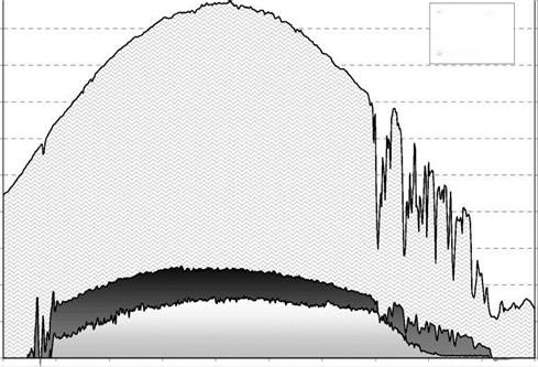
The room temperatures did not exceed 26 °C until 17:00. The chilled ceiling system was almost not able to transfer the cooling energy to the rooms. Hence, the system ran on very low temperatures in the afternoon at 13:00 to 15:00. At 16:00 the cooling performance of the chiller was slowly dropping. The reason lies in the decreasing performance of the solar collectors when the azimuth is increasing. In addition the sky became cloudy. Hence, the heat gains dropped and the cooling power as well (refer Fig. 4 and 5). After 17:00 no notable cooling power could be generated.
Figure 5 shows the operational conditions of the chiller. The average COP over the day was 0.61.
|
|
|
|
|
|
|
|
|
|
|
|
|
|
|
|
|
|
300 200 100
09:00:00 10:00:00 11:00:00 12:00:00 13:00:00 14:00:00 15:00:00 16:00:00 17:00:00 18:00:00 19:00:00
Time [hh:mm:ss]
Fig. 4: Heat Fluxes (direct cooling)
|
Objective analytical investment tools, such as Net Present Value (NPV) and Internal Rate of Return (IRR), were used to process the data and set them out to be compared.
Values of NPV and IRR at the end of the estimated service life of the system, 20 years, allow to deciding the economic viability of the installation. As soon as NPV becomes positive, and IRR higher than the banking interest rate, the system starts to be economically viable.
To measure the degree of viability of the installation, the period of time required to reach a positive NPV and an IRR higher than 5% was calculated.
Absolute values of cost and maintenance were also taken into account, showing the influence that each of the savings have, depending on the housing typology considered.
1.5. Results
As shown in figure 2, the cost of installation depends on the typology of housing and the configuration of the system, being the centralized compression system (which is identical for all the cases) the
cheapest one, and the centralized absorption system (also identical for the three housing typology) the most expensive one. Decentralized compression system is more expensive as far as the size of the individual house is smaller, because of the high number of splits required.
6-apartment-building decentralized system is the one which has the highest energy consumption, because of the high simultaneity of use. In absolute terms, the energy consumption cost of the absorption system is the cheapest, followed by the centralized system and the decentralized systems in decreasing surface order respectively.
Once shown the absolute initial and operation costs of all the systems, the results of the comparison between using an absorption cooling system and the rest of the considered are described.
 |
 |
||
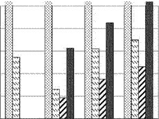
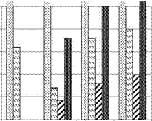
The objective analysis of costs and savings data from the different technologies threw the results shown in the graphics below:
Fig. 4.a Period for NPV>=0 Fig. 4.b Period for IRR>=5%
As expected, the time period required to reach a balance between incomes and expenses of the absorption system, without external aids, exceeds its service life-time. Only considering environmental criteria, its installation could result profitable. The most probably scenario, SBS_CHT_SHW, is the one which gives the best results, with a minimum period of less than five years to get a positive NPV.
It is followed by the second scenario, which only considers the public subsidy. The complementary energy savings obtained by using the solar field to pre-heat sanitary and central heating water are not enough to justify the installation of such a big-surfaced solar field.
Related to the energy consumption of each housing typology, the time required to get a positive NPV grows with the size of the house, being proportionally inverse to the simultaneity of use.
Looking at Fig. XXX, the values of NPV and IRR in the second and third scenarios make the system economically attractive to be installed. It is clear that the solar cooling system will be more viable as far as the consumption of the electric system is higher. Maximum consumption occurs in the building of 6 apartments, where the bigger simultaneity factor increases energy needs.
Taking into account the second and fourth scenarios, the fact that the subsidy was granted or not, could be the angular key_that makes viable the project.
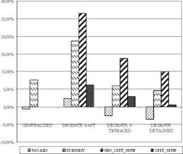 |
Fig. 5.a NPV in the 20th year Fig. 5.b IRR in the 20th year
advantage of the additional uses of the solar field. Despite the fact that the operation costs are very low, its high initial cost hinders a reasonable period of return.
Due to the small number of low-powered absorption chillers, it would be profitable to centralize them, refrigerating the air of a group of small houses. The smaller the house, the bigger the simultaneity of the use factor, and consequently, the bigger the energy consumption avoided.
By considering a public subsidy to the solar field, profitability could turn positive. That is not enough; profitability rate should be higher to counteract the big initial cost. By adding the effects of sanitary and central heating hot water pre-heating, positive results are obtained.
The most profitable housing typology to use the solar cooling systems is the 6 apartments building, because of its high simultaneity of use coefficient and the habitual splits overpowering.
To conclude, it is remarkable that the results of this analysis are very close to getting a real economic viability, but it requires public support and a large campaign to make people aware of environmental care. This would boost the number of installations, increasing the investment in R&D, which will cause the development of the solar cooling sector, promoting its economic profitability..
[1] ANAGNOSTOU, J., PRITCHARD, C., TSOUTSOS, T. et al. (2003). “Solar cooling technologies in Greece. An economic viability analysis”. Applied Thermal Engineering, 23, 1427-2439.
[2] FLORIEDS, G. A., KLGIROU, S. A., TASSOU, S. A. et al. (2002). “Review of solar low energy cooling technologies for buildings”. Renewable and Sustainable Energy Reviews, 6, 557-572.
[3] GARCIA CASALS, X. (2006). “Solar absorption cooling in Spain. Perspectives and outcomes from the simulation of recent installations”. Renewable Energy, 31, 1371-1389.
 |
 |
 |
|
The energy equations related to the adsorber, which will be given next, correspond to a multi-tubular system, whose inner surface exchanges heat with the water coming from the hot storage tank or from the water supply network, depending on the stage of the cycle. The adsorbent occupies the space delimited by the external wall of the tube and the corrugated fins.
Fig. 2 — Fin-tube heat exchanger and the simplification by annular fins
For the heat transfer in the adsorbent medium, the following model assumptions have been considered: (a) the pressure is uniform; (b) the heat conduction is two-dimensional (axial and radial) as detailed in Fig. 2; (c) the adsorbent-adsorbate pair is treated as a continuous medium in relation to thermal conduction; (d) the convective effects and pressure drops are negligible; (e) the condenser and evaporator are ideal, i. e. they have a constant temperature during the isobaric phases; (f) all the adsorbent particles have the same properties (including shape and size); they are uniformly distributed throughout the adsorbent, and in local thermal equilibrium with the adsorbate and the surrounding gaseous phase; (g) the gaseous phase behaves as an ideal gas; (h) the properties of the metal and the gaseous phase are assumed to be constant; (i) the properties of the heat transfer fluid, as well as those of the adsorbate, are considered as temperature dependent. It results the following equation
[Pi (CPі + aCP2 )] ] = к V2T + qst p ^ (2)
d t d t
where Cp is the specific heat (indices 1 and 2 refer to the adsorbent and the adsorbate, respectively), p the specific mass and к, the conductivity of the adsorbent. The total derivation of the concentration, a, is given by
The da/dt term depends on the process that occurs in the adsorber. In the case of an isosteric process it is zero and for adsorption or desorption process, the term d lnp/dt is zero. Then, the energy equation for the adsorbent can be written as
where u is a function of the process, 0 for isosteric and 1 for adsorption or desorption process. The condition in the middle of the adsorbent material, between two fins or two tubes comprises the adiabatic boundary condition. Other boundary conditions are in the interface between the adsorbent and the wall of the tubes and the fins. To solve the Eq. (4), the temperature on the wall of the tubes and on the fins are considered known, recalculated for each simulation step by the energy equation
to the tubes and the following to the fins
where P is the perimeter, A is the area, Tt is the tube temperature, Tw is the water temperature, h is the conductance at the interface tube/adsorbent, and hfi is heat coefficients between the fluid and the tubes. The hfi is evaluated as the method described in [3]. The boundary conditions of Eq. (5) are adiabatic in both extremities and, to Eq. (6), they are adiabatic in the middle of the fin and known in the interface tube/fin. The temperature of the water is given by
were mw is the mass flow of water. To solve the system of equations formed by Eq. (1), (4), (5), (6) and (7) a mixed finite-difference and finite-volume method was used and the input data is chosen to be the temperature and the mass flow of the hot water, the number of tubes, the number and the thickness of the fins and the material of the fin. Additionally, the porous medium properties must be known, especially к and h. According to [4], for the AC-35 activated carbon: к = 0.19 W/mK and h = 16.5 W/m2K.
The annual energy consumption for space heating and cooling in a office building of Japan is 359GJ/m2 [4]. About 40% of the annual energy consumption for space heating and cooling will be expected to be reduced using this solar thermal system for the similar type of the office building. Therefore, the reduced annual energy consumption for space heating and cooling in the field test office building is assumed by 57.6GJ/year. The reduced crude oil and the CO2 emission are estimated by 1.5kL and 4ton using the rates of 38.7GJ/kL and 2,649kg-CO2/kL, respectively.
The initial cost of this solar thermal system was 20 million JPY included the construction fee. If this solar system is used for 20 years, the CO2 reduction cost is 250 JPY/kg-CO2.
The solar desiccant cooling system was developed and the system performance was described in this paper. This system was developed as the passive solar thermal system using the renewable energy without the heat source equipment and the dehumidification cooling system for the fresh air.
From the field test results, it was found that the solar desiccant cooling system for office building
was effective throughout a year.
This study was supported by the research funds of NEDO project, Research and Development of
Technologies for New Solar Energy Utilization Systems for FY2005-F2007, and Grant-in-Aid for
Scientific Research (C)(19560598). The authors would like to express their sincere thanks to the
support.
[1] H. Roh, K. Suzuki, Research and Development of Air-based Passive Solar Dehumidification Cooling System, Part 1 Operation Test of Solar Dehumidification Cooling System, Proceeding of JSES/JWEA Joint Conference 2006 (Renewable Energy 2006 Japan Day), pp.309-312. (in Japanese)
[2] H. Roh, K. Suzuki, Research and Development of Air-based Passive Solar Dehumidification Cooling System, Part 2 Field Test of Solar Dehumidification Cooling System in Summer, Proceeding of JSES/JWEA Joint Conference 2007, pp.405-408. (in Japanese)
[3] S. Song, K. Suzuki, H. Roh, Study on the Performance of Dehumidification Cooling System with Solar Thermal and Well Water, Summaries of Technical Papers of Annual Meeting Architectural Institute of Japan 2008, D-2, pp.1209-1210. (in Japanese)
[4] Heat Pump & Thermal Storage Technology Center of Japan, White Paper of Heat Pump and Thermal Storage, pp.335, Ohmsha, 2007. (in Japanese)
Three external circuits are connected to the Millennium MSS Air Conditioning:
Thermal heat source (e. g. MSS solar collectors)
Air conditioning distribution system for cooling and heating (e. g. radiant floor, fan-coil units)
Heat sink for charging and discharging (e. g. swimming pool, cooling tower, air cooled condenser or geothermal holes)
Millennium Mss Air Conditioning System is a modular absorption machine that differs from the “standard” Lithium Bromide type absorption machines in three main aspects:
It has internal storage in each of the two accumulators. This allows the machine to store chemical energy with a very high density. This energy can subsequently be used both for cooling and heating. It is important to emphasize that this is chemical energy, not thermal energy that is stored.
It works intermittently with two parallel accumulators (Barrel A and Barrel B).
It is designed to use relatively low temperatures and is hence optimized for usage with solar thermal collectors. It also works with a stable temperature inside the accumulators, which in turn allows for an effective use of solar thermal collectors.
Millennium MSS Air conditioning system made up of two “barrels” each consisting of a reactor and condenser/evaporator. The two barrels can operate in parallel.
The water returns from the distribution system at a higher temperature than when it left the condenser / evaporator (we have cooled the building). This heat causes the water in the evaporator to boil and the steam passes down to the reactor, where it condenses, since the reactor is relatively cooler. Steam that condenses into water in the reactor will dilute the LiCl solution. The diluted LiCl solution is then pumped through the filter basket, where it mixes with the salt and regains its saturation. The saturation is needed to continuously provide a temperature difference between the condenser/evaporator and the reactor.
|
|
680 mm 680 mm
Barrel ABarrel B
|
Mode |
Storage Capacity * |
Maximum Output Capacity ** |
Electrical COP[7] |
Thermal Efficiency |
|
Cooling |
60 kWh |
10/20 kW |
77 |
68% |
|
Heating |
76 kWh |
25 kW |
96 |
160% |
|
* Total storage capacity (i. e. including both barrels) |
** Cooling capacity per barrel: 10 kW cooling is the maximum capacity. If both barrels are used in parallel (double mode) the maximum cooling output is 20 kW and the maximum heating output is 25 kW.
 |
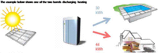 |
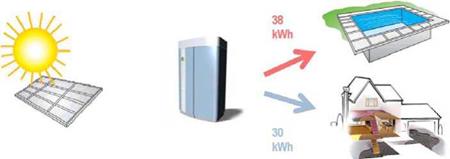
Heating is just cooling in reverse, meaning that the charged energy is extracted as heat by connecting the condenser/evaporator to the heat sink and the reactor to the distribution system. Water returns from the distribution system at a lower temperature than when it left the reactor (we have heated the building). This water boils the water in the condenser/evaporator and steam passes down to the reactor. Steam condenses into water which dilutes the LiCl solution in the reactor. The diluted LiCl solution is pumped through the salt filter basket where it mixes with the salt and regains its saturation. The saturation is needed to continuously provide a temperature difference between the condenser / evaporator and the reactor. During discharging, the heating energy is extracted by connecting the evaporator to the heat sink and the reactor to the distribution system. Under charging, heat can also be extracted by connecting the condenser to the distribution system under charging mode.