Как выбрать гостиницу для кошек
14 декабря, 2021
Сегодня каждый, кто собирается в отпуск и не знает, с кем оставить своего котика или кошку, может во[...]
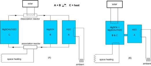 |
The hydration and dehydration of the TCM material take place in a reactor. This may be a separate reactor or the reactor may be integrated in the storage, as shown in the systems presented in Fig. 1.
If the TCM material is a solid, nowadays integrated reactors are used. This has the advantage that it is not necessary to transport the solid material. However, for large storages such as seasonal storage, this also has disadvantages such as a larger sensible heat loss, especially if the storage is not compartimented since then the whole reactor content has to be heated up before dehydration occurs. Also the required heat exchange area is much larger than for a separate reactor. In a separate reactor, it is possible to heat up only the required amount of TCM, thereby making the charging process much more efficient. Similar benefits occur on discharging the material. Also, the heat- and vapour transfer can be optimised within a separate reactor by stirring of the material.
A SGSP collects and stores solar energy all over the year being the storage zone designed in a way that the summer stored energy can be used during winter [7]. Temperatures in the Storage Zone can range from some degrees above ambient temperature to values reaching 100 °C, depending on the Solar radiation available in the region and on the design of the storage zone and thus are appropriated for a wide range of applications. In this work we will focus in Aquaculture facilities.
In fact, the decrease of natural catches and the increase of fish demand as a food source, led to a growing interest in intensive aquaculture. In Portugal, Aquaculture growth, in the last decade, with an hundred farms providing 5% of the total consumed fish. Portugal is also the European country with largest per capita consumption and one of the highest in the world, with an annual average consumption of 60 kg/person.
In order to build a Solar Pond the basic conditions are the union of three factors: good solar irradiation good access to salt (typically NaCl but other available salts can be used) and existence of water. In the presence of these conditions the initial cost of construction evolves basically: excavation and waterproofing of a basin and the installation of some kind of heat extraction device. In a second phase the pond must be monitored making it possible to measure salinity and temperature gradients and the state of the Pond in terms of transparency to solar radiation. Those measurements will allow to predict the beginning of instabilities in the gradient zone allowing consequently its reposition. It may be referred that the basic destabilizing process in the gradient zone is the diffusion of salt which is a very slow process which in fact is the reason why solar ponds actually work. However the presence of the opposing temperature gradient can give rise to double diffusive instabilities and from time to time maintenance operations are necessary to correct the salinity gradient to values well above the critical values for the start of instabilities [8].
These corrections can be the extraction of a higher quantity of thermal energy from the storage zone, if the temperature achieved by the Solar Pond is higher then a known value, the injection of salt if the initial imposed profile is getting smooth, as a consequence of the diffusion process or of any convective instability, the injection of low concentration water on top of the gradient zone in the case of he existence of great losses by evaporation and the introduction of wind suppressors at surface, in the case of the existence of wind ripple at the surface [9].
If only the salt diffusion process was involved as a destabilizing process in a SGSP the expected lifetime of these devices without maintenance would be around ten years. However the above mentioned double diffusion instabilities and also the gradual decrease of transparency lead to the necessity of maintenance of the pond at least two times a year.
The idea behind this paper is to propose a different concept for the maintenance of a solar pond making maintenance operations simple standardized and with an annual periodicity.
H. I. Villafan-Vidales*, C. A. Arancibia-Bulnes, U. Dehesa-Carrasco
Centro de Investigation en Energia, Universidad National Autonoma de Mexico, A. P. 34, Temixco 62580,
Morelos, Mexico.
Corresponding Author, hivv@,cie. unam. mx
Abstract
The radiative heat transfer in a solar thermochemical reactor, for the thermal reduction of cerium oxide, was simulated with the Monte Carlo method. The model takes into account, in a detailed manner, the directional characteristics and the power distribution of the radiative energy that enters to the reactor. It is considered that the reactor contains a gas/particle suspension directly exposed to concentrated solar radiation. The suspension is treated as a non-isothermal, non-gray, absorbing, emitting, and anisotropically scattering medium. The optical properties of cerium oxide were obtained from Mie-scattering theory. From the simulations, the aperture radius and the particle concentration were optimized to match the characteristics of the concentrator.
Keywords: Thermochemical reactor, Solar concentrator, Cerium oxide, Radiative transfer.
Water-splitting thermochemical cycles constitute one of the possibilities for hydrogen production. Greenhouse gas emission can be avoided in these cycles, if solar radiation is used as energy source. Some of them are based on two-step metal-oxide redox pairs like the ZnO/Zn cycle, which has been studied extensively in connection with solar energy utilization [1]. In a recent publication, Abanades and Flamant [2] have demonstrated experimentally a new cycle based on cerium oxide. This cycle consists of the endothermic reduction of Ce2O3 at high temperature (2300 K), where solar energy is used as a source of heat; and of the subsequent steam hydrolysis (700-800 K) of the resulting cerium sesquioxide to produce hydrogen, as in the equations below
2CeO2 (s) ^ Ce2O3 (s) + A O2 (AH = 198 kJ/mol at 2300 K) (1)
Ce2O3(s) + H2O (g) ^ CeO2(s) + H2 (g) (AH = -125kJ/mol at 700 K) (2)
One of the main advantages of this process is that the reduced oxide remains in the condensed phase, while oxygen is released and transferred to the surrounding gas, and the reverse reaction is not carried out during the material quenching. The opposite happens for instance in the reduction of zinc oxide, where zinc and oxygen are produced simultaneously and can recombine if cooling is not efficient [2].
Solar thermochemical reactors are used in the endothermic step of the above cycles. These reactors sometimes feature cavities containing directly irradiated reacting particles. In particular, as in the case of CeO2, cavity receivers may help to compensate for the very low solar absorption of the material particles (scattering albedo of 0.75), although initial demonstrations have been carried out in an all glass reactor. To propose a reactor design that deals with this problem it is necessary to carry out a radiative modelling.
In this work, radiative heat transfer is analyzed within a cylindrical cavity solar reactor by the Monte Carlo method [3]. The reactor is assumed to contain a gas fluidized suspension of radiatively participating CeO2 particles. The model takes into account the radiative characteristics of the particles (absorption and scattering cross sections) as predicted from the Mie scattering theory, and by using the optical properties of CeO2 measured over the UV, visible, and infrared spectrum. The opening of the cavity is assumed subject to concentrated solar radiation from a paraboloidal concentrator.
Fig. 2 shows inorganic materials which have been proposed as a PCM. For comparison also two metals are shown. The lightweight alkali metal lithium has a high melting enthalpy, whereas metals with a high molar mass, such as tin show low enthalpies (Fig. 2). One major disadvantage of lithium is the handling. Tin has a high thermal conductivity of a few 10 W/mK in the solid and liquid phase around the melting temperature. However, for large scale systems tin is not attractive from an economical point of few due to the low melting enthalpy and the high price per mass. For temperatures below 100°C, salt hydrates are a major PCM option. There are also salt hydrates above 120°C (Fig. 2)[7,24]. However, the release of water and encapsulation at these temperatures can be regarded as challenging.
|
Metals (solid-liquid) |
|
Anhydrous Salts |
|
Alkali Lithium 181°C, 432 J/g |
|
Others Classified by anions, typical cations are Li, K, Na, Ca, Mg |
|
solid-liquid Nitrates Nitrites Hydroxides Thiocyanates Chlorates Chlorides |
|
solid-solid Na2SO4 250°C, 60 J/g KOH 250°C, 110 J/g |
|
Salt Hydrates MgNO32H2O 130°C MgBr2-6H2O 172°C |
 |
— Inorganics
Fig. 2. Inorganic PCMs in the temperature range 120 to 250°C.
There are solid-solid and solid-liquid phase transitions of anhydrous salts which can be utilized. As low cost PCM with solid-solid phase transition, sodium sulphate (Na2SO4) has been examined [24, 25]. The transition enthalpy is rather low (Fig. 2) and difficulties with the mechanical stability
have been reported [25]. Other solid-solid PCMs, such as anhydrous KOH, have been also suggested (Fig. 2)[1,5,24].
There are different types of anhydrous salts and salt mixtures with a melting temperature in the range 120 to 250°C. Table 2 summarizes suggested PCMs in thermal energy storage literature classified by their anions [1,3,5,7,8,9,24,26-30]. Additionally, there may be other salts with a suitable melting temperature, such as alkali metal thiocyanates.
|
Table 2. Suggested anhydrous salts and binary mixtures with a melting temperature from 120 to 250°C.
|
The scope, in terms of general system aspects, for Subtask C was the same as that for the whole of Task 32, namely solar heating and cooling systems for residential buildings, principally detached houses for one up to a few families. Buildings with a larger specific heat load (>100 kWh/(m2a) for Zurich climate) are not considered. The main focus was to find storage solutions sized to achieve a significant solar fraction but also for other applications in the heat storage field for domestic housing, especially to reduce the cycling rate of conventional boilers.
Some solutions using PCM have already been tested in full scale pilot plants and some durable commercial products are already on the market for special applications (Cristopia, Rubitherm among others).
Detailed activities included
• the selection of suitable materials,
• the development of storage prototypes and
• the optimization of existing solutions in an integrated system such as the reference combisystem defined by Subtask A.
All solutions with PCM stores were compared to pure water stores.
Fig. 1 shows a classification of processes for PCM storage of heat, in Subtask C only the paraffins (analytical grade) and hydrated salts have been addressed.
|
Fig. 1. Classification of energy storage materials [1]. |
![Подпись: Fig. 1. Classification of energy storage materials [1].](/img/1128/image409.gif) |
In terms of temperature, the storage solutions have been limited to temperatures < 85°C, because the maximum needed temperature for the domestic applications with low temperature heating systems is the DHW demand with around 50°C. The phase change temperature of the materials chosen (mainly sodium acetate trihydrate, partly embedded in a graphite matrix to increase the thermal conductivity) is at about 58°C. For some other tests additional PCM with a lower phase change temperature was chosen (paraffin).
Simulation models of the PCM storage component were developed for different types of PCM heat store philosophies, as no validated models were available for the simulation software TRNSYS at the beginning of the task. These models were validated by laboratory tests before being integrated into a system model within TRNSYS. Each Subtask was responsible to develop an appropriate tool, in order to enable an estimation of the performance of a system with the proposed storage concept.
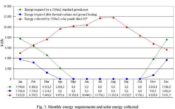
The use of thermal curtains during the heating season can lead to energy savings in the order of 22% to 58% [6]. Because AT from inside to outside is relatively small in our location (lower rate of thermal loss), we will assume that, with the use of these techniques, the energy consumption can be decreased only by 20%. Thus, the consumption on the above example would decrease to approximately 25.651,1 kWh/year and the solar contribution would be 24.60,9 kWh/year (93.8%).
2.1. Ground (root zone) heating analysis
Ground heating at low temperatures (max. 40°C) allows to decrease the inside temperature of a greenhouse between 3° to 6°C. According to the Rutgers report [7] this technique can lead to energy savings in the order of 20% in colder regions of the U. S.A.
A typical temperature pattern for a 60cm tall crop with an outside temperature of -12°C would be a floor temperature of 24°C, a canopy temperature of 13°C and a temperature of 9°C at 120cm above the ground [8]. Thus, setting the mean inside temperature of the air in contact with the glaze at 12°C instead of the previous 14°C, the energy consumption for the simple greenhouse in the example will now be 15.632,9kWh/year (Fig. 3), which represents a reduction of 51,2% on the original demand.
This apparently exaggerated reduction results from the fact that the temperature we are now trying to maintain inside the greenhouse is significantly closer to the outside air temperature. Adding this reduction to the 20% obtained with the use of thermal curtains, the energy consumption will decrease to 12.506,3 kWh/year, representing a total reduction of 61,0%. Figure 3 also shows the energy requirements of our standard greenhouse after being fitted with thermal curtains and root zone heating.
|
|
The x-rays emissions with energy characteristics of the composite chemical elements let completed of the qualitative and quantitative elemental analysis on elemental compositions distributed on a sample surface and in a depth of 1-2 microns.
|
Fig.3. Point spectrum (yellow) of the point area A of the NaNO3 /KNO3 eutectics/graphite NG (20%) composite, compared to the integral spectrum (red) scanned for the sample section. Peak energy levels characterize chemical elements: K, Na, N2, O2, and C. |
 |
The EDS spectra were used for a qualitative element analysis of the composite sample. Peak energy levels characterize chemical elements: K, Na, N2, O2, and C. (Fig.3.). Comparable EDS qualitative elemental analysis on both, a point elemental spectrum and an integral elemental spectrum made on the Area A of NaNO3 /KNO3 eutectics/ graphite NG (20%) composite indicate negligible shifting in energy levels.
Different areas and segments of the same composite sample were EDS scanned, but the element determination shows variety of elemental distribution in different sections taken across the solidified salt melts in the graphite matrix. The element concentrations in micro-volumes of the composite were calculated by quantitative element analysis of the peak energy levels from EDS spectra. The calculated data for element concentration of two different area of the same sample were summarized in Table 5.
|
Table 5. EDS quantitative point elemental analysis of the NaNO3/KNO3eutectics/graphite (20%) composite. Element concentration is measured in weight percentage (wt%).
|
Element concentration presented on Table 5, suggest the element K-rich area in the point area A of the composite sample scanned. The concentration of the element K (from KNO3) is 21.69 wt%, calculated in the fixed point area A of a salt/graphite composite, while the concentration of the
element Na (from NaNO3) is calculated as 9,81 wt%. The calculated element concentrations at a point area B show different values than values for point area A. So, the chemical element concentrations vary depending on spectral area scanned.
The EDS calculated data illustrated clearly the variations in the K and Na element concentrations fixed at different point areas but scanned for the same sample of the salt/graphite composite after its re-crystallization. Therefore, the elemental distribution of salt eutectics is not homogeneous and defines some irregularity in the composite structure and thermophysical properties of the salt/graphite composite.
Thermal behaviour of the novel KNO3/NaNO3eutectics/graphite composite depends on intermolecular interaction of both components: salt and graphite. Correlation between thermal and structural analysis of the composite allows identifying the factors for efficient release of heat absorbed and stored.
Solidification of the re-melted KNO3/NaNO3 eutectics in graphite composite led to elemental separation and forming the Na-rich spherical masses and the K-rich layered structure over the graphite plane, clearly proved by methods of x-ray microanalysis. As the products of chemical degradation or chemical reaction were not identified, the inhomogeneous elemental distribution characterizes the salt in salt/graphite composite structure and presents a factor for proper eutectics salt crystallization, finally responsible for structural and thermal stability of composites during repeatable heat charging/discharging process.
[1] K. Lafdi, O. Mesalhy, A. Elgafy, “Graphite foams infiltrated with phase change materials as alternative materials for space and terrestrial thermal energy storage applications”, CARBON, 46 (2008) 156-167.
[2] Z. Zhang, X. Fang, “Study on paraffin/expanded graphite composite phase change thermal energy storage material”, Energy Conversion and Management, 47 (2006) 303-310.
[3] S. Pincemin, R. Olives, X. Py, M. Christ, “Highly conductive composites made of phase change materials and graphite for thermal storage”, Sol. En. Mat. & Sol. Cells, 92 (2008) 603-613.
Making sure that air velocity stays below the critical value, a constant sand flow and a steady state temperature field specific for cross flow heat exchangers similar to Fig. 2 can be obtained.
The heat transfer effectiveness is defined as the ratio of actual and maximum possible heat flow. In a system with different products of mass flow rate and heat capacity for the two media, the maximum possible heat flow is defined by the lower value:
s _ Q (4)
(m cp L •( — TS, in)
As for the power plant operation both high sand output temperature and low receiver air heat losses are desired, for the heat exchanger measurements it is aimed for balanced products of mass flow rate and heat capacity for air and sand.
For an effectiveness measurement with sand grain size 1-2 mm the following values were measured: Ta, hi=687 °C, TS, in=25 °C, mA =0.0143 kg/s, mS =0.0205 kg/s, TA, out=62.4 °C, Ts, out=427.5 °C
The lower product of mass flow and heat capacity is defined for air. Further decrease of sand flow is impeded by the valve design, otherwise higher sand output temperatures could be obtained.
The heat exchanger effectiveness comes to
|
______________ Q_______________ _ mS • cp, S (Tr. f ^ Tin, S ) • (Tin, S — Tref ) ‘ (cp )A * ( — Ts,„, ) _ (43kg/s • cp) • (687°C — 25°C) |
mS • cp, S(Tr. f ^ T„„.,S) * (Tout, S — Tr. f )
(0.0143kg/s • cp )*(687°C — 25°c) (5)
0.0205 — • 920 J •(427.5°C — 25°C)
|
0.748 |
![]() ________ s kg • К v___________________ ’ _ 7591W
________ s kg • К v___________________ ’ _ 7591W
0.0143^ 4072 — l(687°C — 25°C) 10148W
s kg • К)y ’
The measured heat exchanger effectiveness is clearly below the values obtained from simulation of 0.8-0.9, according to section 2.2. This is partly explained by heat losses on the heat exchanger surfaces and air leakages. Additionally, it is a result of disturbing effects due to the limited heat exchanger width.
Figure 5 shows a front view on the air outflow area and the according air outflow temperatures. As expected the temperatures increase to the bottom, similar to the right line in the middle area of Fig. 2. However, moving on horizontal lines from the centre to the heat exchanger frame the temperatures increase, too. Whereas for determination of effectiveness the air and sand temperatures are measured in the centre section, the energy balance is largely determined by the differing temperatures on the heat exchanger frame region on the left and right side. The temperature increase is attributed to heat conduction effects in the steel frame and air leakages between steel frame and sand.
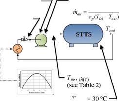
The charging performance of the tank concepts is to be assessed under both constant and variable inlet conditions. This is illustrated in Figures 12 to 14 and Table 3. The energy curve applied to the variable conditions was taken from TRNSYS simulation data provided by the Drake Landing network. The energy input curve for the Variable Temperature and Variable Flow Rate (VTVFR) case below represents a clear day with a sudden drop in available energy to drive a decrease in the inlet temperature.
The conditional algorithm for the VTVFR case was derived from the sequence of control currently in use at the DLSC. However, the upper limit on the inlet temperature (60 °C) was chosen arbitrarily as the value is strongly dependent upon environmental considerations. Thus, although 60 °C shall be used for this test, it should be noted that future simulations could determine the system’s sensitivity to various upper temperature limits.
|
|
|
Thermal Reservoir |
|
=10kg/5 |
|
initial |
|
= 25 °C |
|
Figure 12. Constant Temperature and Constant Flow Rate (CTCFR) |
|
Desired Temperature Tdes = 60 °C |

|
Desired Flow Rate Q (t) |

|
Energy Profile, Q(t) |

|
initial ’ |
![]()
|
Figure 14. Variable Temperature and Variable Flow Rate (VTVFR) |

 Upper Temperature Limit on Delivered Energy = 60 °C
A. Hauer
Bavarian Center for Applied Energy Research — ZAE Bayem Dept. 1: Technology for Energy Systems and Renewable Energy Walther-Meissner-Str. 6, D-85748 Garching hauer@muc. zae-bayern. de
Abstract
Based on the laws of thermodynamics and the sorption theories, possibilities and limits of sorption storages for solar applications can be defined. For the storage of thermal energy closed and open sorption systems as well as solid and liquids sorbent materials can be utilized. Each system has its own advantages and disadvantages. Over the last years a number of R&D activities were performed. Examples are a closed adsorption storage system in Austria for seasonal storage of solar heat and an open liquid absorption storage system for solar cooling in Singapore. The conclusion of this paper is that even the high storage capacities and the possibility of providing heat and cold of sorption storages do not solve all solar thermal storage problems. It is still necessary for each system constellation to find an appropriate application and to carefully check the relevant boundary conditions.
Keywords: Sorption Storage, Adsorption, Absorption, Liquid Desiccant Cooling
Thermal Energy Storage (TES) is crucial for the efficient use of solar energy. TES systems are able to buffer the variable supply of solar radiation in a short term TES. Seasonal TES systems are able to keep the thermal energy surplus from summer to winter.
A high storage capacity and low thermal losses over the storage period are preferable for TES systems in general. Looking at the three possible technologies for TES — sensible, latent and thermochemical TES — thermochemical systems seem to have optimal properties for solar thermal applications, since they are able to achieve the highest capacities and have no thermal losses.
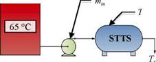
Thermochemical TES are utilizing reversible chemical reactions. The number of possible reactions for this application from first principle is huge, however only very few are suitable with respect to their reaction temperature. The processes of adsorption on solid materials or absorption on liquids are the most investigated ones. Figure 1 shows the adsorption process schematically.
|
Adsorption means the binding of a gaseous or liquid phase of a chemical component on the inner surface of a porous material. During the desorption step — the energetic charging step — heat is provided to the sample. The adsorbed components — in this example water molecules — are removed from the inner surface. As soon as the reverse reaction — the adsorption — is started by adding water molecules to the sample, the molecules will be adsorbed and the heat, brought into the system during desorption will be released. The adsorption step represents the discharging process.
Figure 2 shows the examples of liquid and solid open sorption storage systems. In both cases the desorption is activated by a hot air stream carrying the heat of desorption. For the solid a packed bed of adsorbent pellets and for the liquid solution a reactor are blown through, leaving the packed bed dry and the solution concentrated.
|
air + water :nt ed air |
|
Adsorbent Packed Bed! |
|
air + water |
|
Absorber |
|
heat of |
|
S ДЩД ~~ -| Ї- |
|
oncentrated Salt Solution |
|
Diluted |
 |
 |
Solid Adsorbent Liquid Absorbent
Figure 2: Examples of open sorption storage systems during desorption / charging
TES can be achieved by separating the desorption step (charging mode) from the adsorption step (discharging mode). After desorption the adsorbent and the absorbent can theoretically remain in the charged state without any thermal losses due to the storage period until the adsorption process is activated.
|
Humidifiei |

|
Cool |
![]()
![]() Solid Adsorbent Hot
Solid Adsorbent Hot
і і 0гУ
Liquid Absorbent Dry Cool
Figure 3: Examples of open sorption storage systems during adsorption / discharging
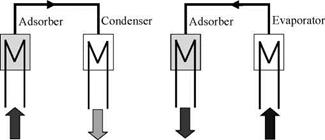
Figure 3 shows schematically the discharging of open sorption storages. Humid air blown through the storage becomes dry and can be used for dehumidification or, by adding a
humidification step, for cooling (desiccant cooling systems). If solid adsorbents are used the air might be very hot after the adsorption. This heat can be used for heating purposes.
Open and Closed Sorption Storages
The charging process of a sorption TES is a reaction where two components A and B — adsorbent and adsorbed water — will be separated by the input of heat Q and entropy S : AB o A + Bg. The water will be evaporated in this step.
In an open system Bg can be released into the ambience (see figure 4). For the discharging Bg has to be provided to the reactor in sufficiently high concentrations. The water vapour will be adsorbed again and the stored heat can be released.
Figure 5: Schematic view of the thermodynamics of a closed sorption storage
The evaporated component Bg will be condensed during the charging step in a closed (evacuated) system. This is in order to reduce the volume. The heat of condensation and its entropy have to be dissipated into the ambience. For discharging the condensed water has to be evaporated again in order to be adsorbed at the reactor [1].
Closed Sorption Storage Systems
A closed sorption system is shown in figure 6. It is based on the same physical effect as the open storage. However the engineering is quiet different from open sorption systems. Closed system could be more precisely described as evacuated or air-free systems. The operation pressure of the fluid to be sorbed can be adjusted in theses systems. In closed systems chemical components, which do not exist in the atmosphere, can be used, because there is no connection to the ambience.
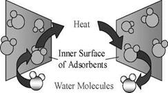
Figure 6 is showing a closed sorption system using water vapor as adsorptiv. The heat has to be transferred to and from the adsorbent by a heat exchanger. This holds also for the condenser/evaporator. Heat has to be transported to the adsorber and at the same time the heat of condensation has to be distracted from the condenser in order to keep up the water vapor flow from the adsorber to the condenser during the desorption. During adsorption the heat of adsorption has to be taken from the adsorber and the heat of evaporation has to be delivered to the evaporator. Is
this not possible, the sorption process will reach thermodynamic equilibrium and the flow of water vapor comes to a stop.
The main problem in the system design is the heat and vapor transport in and out of the adsorbent. Advanced heat exchanger technologies have to be implemented in order to keep up the high energy density in the storage, which would be reduced by the amount of "inactive" heat exchanger material.
|
Water Vapor Water Vapor
QDes Qcond QAds QEvap Figure 6: Closed Sorption system |
Thermal energy storage can be realized by closing the valve between adsorber and condenser/evaporator after desorption. The energy density expected is reduced compared to open sorption storages due to the fact that the adsorptive (water vapor in this case) is part of the storage system and has to be stored as well. In the case of Zeolite or Silicagel as adsorbent this is about 30% to 40 % of the weight of the storage material [2], [3].
Closed systems are able to reach higher output temperatures for heating applications compared to open systems. Furthermore they can supply lower temperatures for cooling, e. g. it is possible to produce ice in the evaporator [4].