Как выбрать гостиницу для кошек
14 декабря, 2021
Сегодня каждый, кто собирается в отпуск и не знает, с кем оставить своего котика или кошку, может во[...]
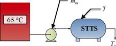
The charging performance of the tank concepts is to be assessed under both constant and variable inlet conditions. This is illustrated in Figures 12 to 14 and Table 3. The energy curve applied to the variable conditions was taken from TRNSYS simulation data provided by the Drake Landing network. The energy input curve for the Variable Temperature and Variable Flow Rate (VTVFR) case below represents a clear day with a sudden drop in available energy to drive a decrease in the inlet temperature.
The conditional algorithm for the VTVFR case was derived from the sequence of control currently in use at the DLSC. However, the upper limit on the inlet temperature (60 °C) was chosen arbitrarily as the value is strongly dependent upon environmental considerations. Thus, although 60 °C shall be used for this test, it should be noted that future simulations could determine the system’s sensitivity to various upper temperature limits.
|
|
|
Thermal Reservoir |
|
=10kg/5 |
|
initial |
|
= 25 °C |
|
Figure 12. Constant Temperature and Constant Flow Rate (CTCFR) |
|
Desired Temperature Tdes = 60 °C |

|
Desired Flow Rate Q (t) |

|
Energy Profile, Q(t) |

|
initial ’ |
![]()
|
Figure 14. Variable Temperature and Variable Flow Rate (VTVFR) |
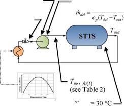 Upper Temperature Limit on Delivered Energy = 60 °C