
Как выбрать гостиницу для кошек
14 декабря, 2021
Сегодня каждый, кто собирается в отпуск и не знает, с кем оставить своего котика или кошку, может во[...]
|
в(т) = exp |
|
C(ARa) |
|
-1 |
|
(4) |
|
T |
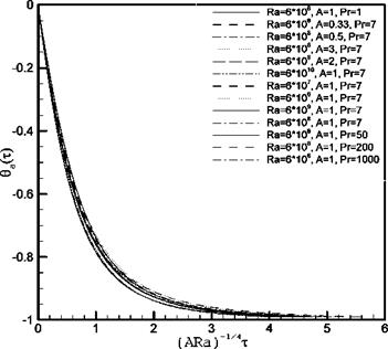
The evaluation of the long-term behavior of the fluid is well represented by the transient average temperature 0a(x). Thus, by writing the global energy balance inside the tank, it has been shown that the temperature can be characterize in terms of the three control parameters of the flow (Ra, Pr and A) as follow:
The approach for verifying the scaling relation eq.4 is firstly done by examining the dependence of these scaling relation on individual control parameters Ra, A, and Pr respectively, which has been achieved by carrying out a series of numerical simulations with several selected values of a specific parameter while keeping the other control parameters unchanged with selected values, and then by examining the combined dependence of the scaling relations on all control parameters, by combining the three sets of individual numerical results. Specifically, numerical simulations with Ra=6.106, 6.107, 6.108, 6.109, and 6.1010 while keeping A=1 and Pr=7 unchanged to show the dependence of the scaling relations on Ra; simulations with A=1/3, 1/2, 1, 2, and 3 while keeping Ra=6.108 and Pr=7 unchanged will be carried out to show the dependence on A; and simulations with Pr=1, 7, 50, 200, and 1000 while keeping Ra= 6.108 and A=1 unchanged to show the dependence of the scaling relations on Pr.
Fig. 2 shows the numerically mean temperature въ (т) obtained for all the numerical cases to prove the dependence of the scaling relation eq.1 on the control parameters Ra, A and Pr =7. The scaling relation eq. 1 shows that the dependence of вa (т) on (ARa) goes like (ARa)-14, and the time series of в3 (т) are well defined with this scaling.
|
1st International Congress on Heating, Cooling, and Buildings " ‘ 7th to 10th October, Lisbon — Portugal *
Fig. 2. Times 0a(x ) again (ARa)-1/4 corresponding to different tested cases. |
The data set from the several computations carried out has been fitted to the scaling relation eq. 4. In order to find the specific values of the proportionality constant C for each run, the fitting process has been done by mean of the GNU Regression, Econometrics and Time-series Library (gretl) [13]. This tool provides the solution to the non-linear function, minimising the sum of the squares of the deviations.
|
Table 1. Values of Ci for each case and thier corresponding standard deviations.
|
From the curve-fitting method, the constant C for each run with the minimal standard deviation (denoted as sdi), are listed in Table 1. It is noted that the variation in the C values is of the order of 8%, indicating that a single C value will provide a good representation of the behavior of the flow. This general value of C is found in the same fashion for all 13 sets of data by combining them into a single average set, as C = 1.119.
*
The transient process of cooling-down a fluid has been investigated numerically. In order to decribe the long term behaviour of the fluid inside the storage tank, the transient profile has been represented by the mean the average fluid temperature.
This analysis has led to the identification of the significant parameters that define the transient natural convection phenomena inside the storage: the Rayleigh number Ra, the aspect ratio H/D, and the Prandtl number variations Pr.
Variations on the different relevant parameters have been taken into account. The average fluid temperature at each instant of all numerical simulations, have been fitted to a scaling relation proposed in terms of the identified relevant parameters. The non-dimensional temperature (0a) is well represented by the correlation obtained. The similar correlation has been obtained in [14].
[1] M. Cotter, M. Charles, Transient cooling of petroleum by natural convection in cylindrical storage tanks.
I. Development and testing the numerical simulator, International Journal of Heat and Mass Transfer, 36 (8) (1993) 2165-2174.
[2] M. Cotter, M. Charles, Transient cooling of petroleum by natural convection in cylindrical storage tanks. II. Effect of heat transfer coefficient, aspect ratio and temperature-dependent viscosity, International Journal of Heat and Mass Transfer, 36 (8) (1993) 2175-2182.
[3] A. Ivancic, A. Oliva, C. D. Peres-Segarra, M. Costa, Heat transfer in vertical cylindrical enclosures for supercritical Rayleigh number and arbitrary side-wall conductivity, International Journal of Heat and Mass Transfer, 42 (2) (1999) 332-343.
[4] R. C. Oliveski, A. Krenzinger, H. A. Vielmo, Cooling of cylindrical tanks submitted to natural internal convection. International Journal of Heat and Mass Transfer, 46 ( 2003) 2015-2026.
[5] R. C. Oliveski, A. Krenzinger, H. A. Vielmo, Comparison between models for the simulation of hot water storage tanks. Solar Energy, 75 ( 2003) 121-134.
[6] W. Lin, S. W. Armfield, Direct simulation of natural convection cooling in a vertical circular cylinder, International Journal of Heat Mass Transfer, 42 (1999) 4117-4130.
[7] W. Lin, S. W. Armfield, Natural convection cooling of rectangular and cylindrical containers, International Journal of Heat Fluid Flow, 22 (2001) 72-81.
[8] I. Rodriguez, J. Castro, C. D. Peres-Segarra, A. Oliva, Unsteady numerical simulation of the cooling process of vertical storage tanks under laminar natural convection, International Journak of Thermal Sciences, doi: 10.1016/j. ijthermalsci.2008.06.002 (2008).
[9] S. V. Patankar (1980). Numerical Heat Transfer and Fluid Flow, McGraw-Hill, New York.
[10] P. H. Gaskel et. and A. K.C. Lau, Curvature-compensed convective transport: SMART, a new boundness-presserving transport algorithm, International Journal for Numerical Methods in Fluids, 8 (1988) 617-641.
[11] J. P. Van Doormal and G. D. Raithby, Enhancements of the SIMPLE method for predicting incompressible fluid flows. Numerical Heat Transfer, 7 (1984) 147-163.
[12] L. Davidson, Calculation of the turbulence buoyancy-driven flow in a rectangular cavity using an efficient solver and two different low Reynolds number к— turbulence models. Numer. Heat Transfer Part A, 18 (1990) 129-147.
[13] A. Cottrell, R. Lucchetti, (2005). Gretl, GNU Regression, Econometrics and Time-series Library, version
D. Haillot12*, V. Goetz1, X. Py1and M. Benabdelkarim2
1 PROMES CNRS UPR8521 : PRocess, Materials and Solar Energy Laboratory, Universite de Perpignan Via
Domitia, Rambla de la Thermodynamique Tecnosud 66100 Perpignan, France
2 Saunier Duval Eau Chaude Chauffage Industrie, 17 rue de la Petite Baratte, BP 44315 Nantes Cedex 03
Corresponding Author, didier. haillot@univ-perp. fr
Abstract
A new integrated collector storage (ICS) system is investigated in this paper. This innovative collector includes a composite, made of compressed expanded natural graphite (CENG) and phase change material (PCM), just behind a solar absorber. This composite thanks to its high storage capacity and thermal conductivity, allows storage and release of solar energy at high power level.
ICS, including CENG/PCM composite, has been realised and tested under charge and discharge processes. Comparison between experimental and numerical results allowed us to validate a mathematical model that describes thermal process in the ICS.
Keywords: Integrated Solar Collector, thermal modelling, phase change materials (PCM).
Integrated solar collector-storage (ICS) system, compared to conventional domestic heating water systems, combines collection and storage of thermal energy in a single unit. Using PCM as storage medium, such system presents several advantages:
• reduction of collector temperature maximum,
• enhancement of the useful efficiency [1],
• reduction or even avoidance of storage tank volume,
• new storage functionality.
Few ICS-PCM have been already studied in several ways (as example, salt hydrate above the absorber[2], paraffin in tube). In this communication we propose a new type of ICS with a composite material based on phase change materials (PCM) and expanded natural graphite (CENG) as storage media. These composite materials are of particular interest in this study due to theirs enhanced properties. They present high storage capacities and high effective conductivity which increases thermal transfer between storage medium and fluid transfer [3]. An ICS prototype (figure 1) including PCM/CENG composites has been realised. The technical feasibility and the obtained thermal performance of the ICS are first described.
The corresponding numerical model describing the thermal process during the charge and discharge of the composite material is presented according to the particular geometry. Then, the obtained experimental results have been compared to the data from numerical model.
Unfortunately there are no typical or measured infiltration rates available for the building types used in this study. For the purposes of this paper the average air leakage rate found by a UK study
[13] is used (13.1 ACH50). The study uses the fan pressurization method (or “blower door method”). This rate is converted to an infiltration rate under normal conditions as described in the literature [14,15]. The whole building ventilation rates used in the models are based on the ANSI/ ASHRAE Standard 62.2-2007 [16].
|
Table 3. Calculated infiltration and ventilation rates per zone
|
The minimum whole building ventilation rates suggested by the standard include a default infiltration rate of 10L/s per 100m2. The standard also defines that if a higher infiltration rate applies then the minimum ventilation rate can be decreased by half of the excess of the known infiltration rate. For bathrooms and kitchens the continuous ventilation rates suggested by the same standard are used and are 10 L/s and 5 ACH respectively. Erro! A origem da referenda nao foi encontrada. shows the ventilation rates used for the various zones of the house, calculated in relation to the average infiltration rates for the houses.
The main findings of the studies on closed adsorption storage, as reported by SPF in Switzerland, are the following:
• The geometrical parameters and the dynamical behaviour of the closed sorption system are strongly related. The available temperature depends on the pressure of the sorbate and the driving force is limited by the external temperature ranges — the low temperature energy source — the mid temperature source/sink and — the high temperature energy source, which is aimed to be a solar collector.
• The measured temperature behaviour as a function of time in the sorbent module and in the sorbate (water) tank is indicating an optimum cycle time in the range 3 to 8 min. The determined power output shows a higher system performance for cooling than for heating because of a higher heat transfer in the evaporation of the sorbate. Regarding the short cycle time and the higher power output for cooling, the adsorption process is more suitable for cooling application of a thermally driven heat pump. At this development level a scaling up to long term storage is doubtful.
• A further understanding of the sorption system will be needed for a maximum power design because it will be determined by the geometric dimension of the system i. e. particle distribution of the sorbent fixed bed in a defined solid sorbent — liquid sorbate material combination.
• In a comparison of the solid adsorption and a the liquid absorption processes the liquid system could be favoured for storage application — exactly because the fluid can be pumped from one storage tank through a reaction zone to an other storage tank.
• Thermal energy storage in a sorption storage system is depending on the available thermal energy sources and sinks. So, the selection of the sorbent — sorbate material combination has to be done under these general conditions, beside of others. With the idea of the reduction of moving parts i. e. pumps in a solid sorption system the power limiting low heat transfer coefficients are leading to a layer structure in the sorption module. But a layer structure applied to a heat exchanger will limit the energy output of the system.
At first, the performance of the storage was determined in standalone tests. For this, a total of 70 charge and discharge cycles were performed and several parameters recorded. Fig. 4 shows typical temperature-time curves at the inlet and outlet of the two storage modules and at two locations in the PCM. Using the volume flow of the heat transfer fluid and its heat capacity, the heating / cooling power were calculated and then by integration over time the stored energy. The left side of fig. 4 shows the results for loading, which is heating the storage modules, the right side for unloading, that is cooling down the storage modules.
The evaluation of the recorded data showed that charging the storage modules latent interval at design temperature 36 °C takes about 10 hours. The measured power at charging with a supply temperature of 36 °C was 11 kW, which is close to the design value of 12 kW. The measured power at discharge with a supply temperature of 22 °C was 10 kW. The extended discharging process (about 12 hours), is caused by the fact that the thermal resistance within the PCM increases with time. The subcooling oft the PCM is about 2 K, and only observed at the start of the discharge process. The integration of the power over time, which gives the stored heat, shows that the storage achieves the design storage capacity of 120 kWh. Further on, the tests showed no degradation of the storage capacity during the 70 cycles.
|
time [h:min] |
|
time [h:min] |
|
time [h:min] |
|
36 о ф 32 =3 го О) 28 E <D 24 20 |
|
outlet storage 1 outlet storage 2 storage 1 storage 2 inlet |
|
8 |
|
6 |
|
00:00 02:00 04:00 06:00 08:00 10:00 12:00 14:00 time [h:min] 10′
|
|
і 4 2 |
|
0 00:00 02:00 04:00 06:00 08:00 10:00 12:00 14:00 time [h:min] time [h:min] |
 |
 |
Fig. 4. Operational results of the two latent heat storage modules. Temperatures (top), power (centre) and
stored energy (bottom) during loading (left) and unloading (right) of the storage modules.
The performance of the latent heat storages depending on the logarithmic mean temperature difference in the latent interval during several charging and discharging cycles is shown in fig. 5 and fig. 6. They show an almost linear relationship, which is caused by the respective thermal resistances and the fact that the measurements were performed while the PCM was in the melting / solidification process.
|
|
OPCM-storage 2 datal PCM-storage 1 datal PCM-storage 2 data2 + PCM-storage 2 data3 ■ PCM-storage 1 data2 + PCM-storage 1 data3 ■PCM-storage 1 data4 |
|
4 |
|
10 |
|
Imtd 11 12 |
 |
Fig. 5. Performance characteristic of both latent heat storages depending on the inlet temperature while
charging.
power [kW]
|
7 — |
|
6 — |
|
5 — |
|
4 — |
|
3 — |
|
2 — |
|
OPCM-storage 2 data1 ■ PCM-storage 1 data1 A PCM-storage 2 data2 OPCM-storage 1 data2 Ж PCM-storage 1 data3 OPCM-storage 2 data3 + PCM-storage 2 data4 ■PCM-storage 1 data4 |
|
0 0 1 2 3 4 5 6 7 |
|
Imtd |
|
9 10 11 12 |
 |
8 1
Fig. 6. Performance characteristic of both latent heat storages depending on the inlet temperature while
discharging.
In summary, the results from the experimental evaluation show that the storage can provide hot water with a temperature of 40 °C for more than two hours, at an average power of 3 kW. The control strategy for discharging according to a specific load requirement is however presently under development.
It is possible to charge the 140 liter HEATPACK prototype with close to the theoretically calculated value of 15 kWh. Hence, this is a PCM storage solution with a storage capacity of over 100 kWh/m3 which is a good value for accomplishing overall cost effectiveness as compared to a stratified hot water storage.
It is desirable to further increase the heat transfer rate within the HEATPACK prototype. One measure is to include finned tubes in the next generation, although here care must be taken not to significantly increase the cost of the tank while doing this. Discussions with potential manufacturers are underway. The next generation design will also be configured for a lower pressure drop on the water side such that the water flow rate can be increased while still using a reasonable sized pump.
The conclusion is thus that with some changes in design, the HEATPACK concept is promising, and after further evaluation it should be ready for taking the project into the commercial phase during 2008 and 2009.
References
[1] A. Hauer, H. Mehling, P. Schossig, M. Yamaha, L. Cabeza, V. Martin, F. Setterwall, (2005). Final Report of the IEA/ECES Annex 17 — Advanced Thermal Energy Storage through Phase Change Materials and Chemical Reactions — Feasibility Studies and Demonstration Projects. www. fskab. com/annex17
[2] R. V. Seeniraj, N. L. Narasimhan, (2008), Performance Enhancement of Solar Dynamic LHTS Module having both Fins and Multiple PCMs, Solar Energy, vol. 82, 535-542.
[3] S. Pincemin, R. Olives, X. Py, M. Christ, (2008), Highly Conductive Composites made of Phase Change Materials and Graphite for Thermal Storage, Solar Energy Materials and Solar Cells, vol. 92, 603-613.
[4] W. Streicher (editor), (2007), Laboratory Prototypes of PCM Storage Units, Report C3 of Subtask C within the IEA Solar Heating and Cooling Programme Task 32, May 2007, www. iea-shc. org/task32
[5] J. Banaszek, R. Domanski, M. Rebow, F. El-Saiger, (1999), Experimental Study of Solid-Liquid Phase Change Spiral Thermal Energy Storage Unit., Applied Thermal Engineering, vol. 19, 1253-1277.
[6] B. Zalba, J. M. Marin, L. F. Cabeza, H. Mehling, (2004), Free-Cooling of Buildings with Phase Change Materials, Int. J. of Refrigeration, vol. 27, 839-849
The system is designed to achieve a solar fraction of 35 to 40 % of the total heat demand. This corresponds to a yearly reduction of 390 tons of CO2 emission. Compared to the original situation (without refurbishment) energy savings of 65 % will be achieved. Operation of the system is planned to begin in summer 2008.
On the one hand detailed investigations such as on the hydraulic behaviour of the store or concerning the influence of ground water on the thermal losses will be carried out. On the other hand an energetic analysis of the entire system including the performance of the heat pump will be conducted.
|
1st International Congress on Heating, Cooling, and Buildings^ 7th to 10th October, Lisbon — Portugal |
|
Fig. 9: Cross section of the GW-TES, location of temperature sensors in the store and in the surrounding soil |
 |
Acknowledgement
This project is supported by the German Federal Ministry for the Environment, Nature Conservation and
Nuclear Safety (BMU: Bundesministerium fur Umwelt, Naturschutz und Reaktorsicherheit), FKZ 0329607J.
The authors gratefully acknowledge this support and carry the full responsibility for the content of this paper.
[1] Pfeil M., "Realisierung eines solaren Nahwarmesystems mit Langzeitwarmespeicher in einem Schul — und Sportzentrum der 1960er Jahre”, 17. Symposium Thermische Solarenergie, 09.-11. Mai 2007, Kloster Banz, Bad Staffelstein, 2007.
[2] Riegger M., Mangold D., Planungsoptimierung und Bau des solaren Nahwarmesystems mit saisonalem Kies-Wasser-Warmespeicher in Eggenstein-Leopoldshafen, OTTI — 18. Symposium Thermische Solarenergie, Bad Staffelstein, 2008.
[3] Ochs F., State of the Art of Seasonal Thermal Energy Storage, Report, Institute of Thermodynamics and Thermal Engineering (ITW), Uni Stuttgart, Stuttgart, 2007.
[4] Ochs F., Heidemann W., Muller-Steinhagen H., Weiterentwicklung der Erdbecken — Warmespeichertechnologie, Forschungsbericht zum BMU-Vorhaben 0329607E (November 2002 bis Oktober 2007), Stuttgart, 2008.
[5] Ochs F., Heidemann W., Muller-Steinhagen H., Modelling and Measurement of the Effective Thermal Conductivity of the Insulation of Buried Heat Stores as a Function of Temperature and Moisture Content, Heat and Mass Transfer (2007), doi:10.1016/j. ijheatandmasstransfer.2007.05.005, 2007.
[6] Benner M., Bodmann M., Mangold D., NuBbicker J., Raab S., Schmidt T., Seiwald H., Solar unterstutzte Nahwarmeversorgung mit und ohne Langzeit-Warmespeicher, Forschungsbericht zum BMBF-Vorhaben, November 1998 bis Januar 2003, ISBN: 3-9805274-2-5, 2004.
Test 3 shows a better distribution of microcapsules of PCM throughout the polyurethane foam than the other manufacturing processes commented above, see Figure 6 (c) and (d).
|
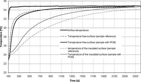
Figure 8 shows a fast heating in the sample with PCM than reference sample. Adhesion results tested are within of the limits (table 2).
|
Figure 8 Thermal performance test of the reference sandwich panel and sandwich panel with PCM (Test 3)
4. Discussion
Thanks to the high thermal storage capacity of microencapsulated PCM, they can confer high thermal inertia to the sandwich panels. Related to test 1 and test 2 were observed problems with the adhesion test, but this problem can be solving if the process is industrialized by the company, as well as, test 2 could improve its thermal behaviour. Another option was studied using the macroencapsulation (rigid container) (Carbonari et al [14]), so that, it was added to one side of the sandwich panel.
In test 3 problem of adhesion test was solved, but a new effect is observed, this time the distribution of the microcapsules is homogeneous, but microcapsules took the air spaces that have the polyurethane foam, and the effect of the PCM is overlap by a possible increase in thermal conductivity.
The goal of this study was to demonstrate the feasibility to use the microencapsulate PCM (Micronal BASF) in sandwich panels to increase its thermal inertia, and therefore, reduce the energy demand of the final buildings. The results shown above include different manufacture processes and the results obtained with these experiments were very promising. The possibility to adapt this technology to manufacture panels allows their installation on ceilings and walls.
[1] D. Banu, D. Feldman, F. Haghighat, J. Paris, D. Hawes, Energy-storing wallboard: flammability test, Journal of Materials and Civil Engineering, 10 (1998) 98-105.
[2] H. G. Barkmann, F. C. Wessling, Use of buildings structural components for thermal storage, Proceedings of the Workshop on Solar Energy Storage Subsystems for the Heating and Cooling of Buildings, Charlottesville (Virginia, USA) (1975).
[3] I. Dincer, M. A. Rosen, (2002).Thermal energy storage. Systems and applications, John Wiley & Sons, Chichester, England.
[4] D. W. Hawes, D. Feldman, D. Banu, Latent heat storage in building materials, Energy and Buildings 20 (1993) 77-86.
[5] T. Wada, F. Yokotani, Y. Matsuo, Equilibria in the aqueous ternary system containing Na+, CH3CO2", and P2O74- between 38 and 85°C, Bul. Chem. Soc. Jpn. 57 (1984) 1671-1672.
[6] I. O. Salyer, A. K. Sircar, R. P. Chartoff, D. E. Miller, Advanced phase-change materials for passive solar storage applications. In: Proceedings of the 20th Intersociety Energy Conversion Engineering Conference. Warrendale, Pennsylvania, USA (1985) 699-709.
[7] M. Shapiro, D. Feldman, D. Hawes, D. Banu, PCM thermal storage in drywall using organic phase change material. Passive Solar J 4 (1987) 419-438.
[8] M. W. Babich, R. Benrashid, R. D. Mounts, DSC studies of energy storage materials. Part 3. Thermal and flammability studies. Thermochimica Acta 243 (1994) 193-200.
[9] D. Banu, D. Feldman, F. Haghighat, J. Paris, D. Hawes, Energy-storing wallboard: flammability tests. J. Mater Civ Eng 10 (1998) 98-105.
[10] A. M. Khudhair, M. M. Farid, A review on energy conservation in building applications with thermal storage by latent heat using phase change materials. En Conv & Management 45 (2004) 263-275.
[12] A. Hauer, H. Mehling, P. Schossig, M. Yamaha, L. F. Cabeza, V. Martin, F. Setterwall, International Energy Agency Implementing Agreement on Energy Conservation through energy storage. Annex 17 Final Report (2005).
[13] B. Zalba, (2002). Almacenamiento termico de energia mediante cambio de fase. Procedimiento experimental, Ph. D. Thesis, University of Zaragoza (Spain).
[14] A. Carbonari, M De Grassi, C. Di Perna, P. Principi. Numerical and experimental analyses of PCM containing sandwich panels for prefabricated walls. Energy and Buildings 38 (2006) 472-483.
A simulation of the night time cooling system was developed in TRNSYS, using the standard components within the library. The model was based on a typical multistorey commercial building with a total floor area of 8000 m2. Rather than simulating the building load, an empirical equation was developed applying standard design loads as provided by the Australian Institute of Refrigeration, Air conditioning and Heating [7] and an assumed load profile, defined by the dry bulb temperature. This approach will produce an overestimation of the load as the solar load is assumed to be maximum for all days.
At the design temperature of 38 oC, the design load is 120 W/m2 or 960 kW. The average load, assumed as half the design load, was assumed to occur at the average summer 3pm temperature. It was assumed that at 23 oC, no cooling was required by the system, below which an economy cycle would deliver cooling. Based on these points, Eqn. (1) was developed for the load of the building.
Q =-3.474 Tdb2 + 276 Tdb — 4509 (1)
where Q is the load in kW and Tdb is the dry bulb temperature in oC.
The system was designed based on average night time conditions during the summer and the design load. Since the specified cooling tower must be capable of operating as a conventional cooling tower, the condenser load was determined from the design load and assuming a COP for a chiller of 3.5.
Based on this load, a cooling tower was sized from the specifications of a local cooling tower manufacturer [8]. This cooling tower had a flow rate of 60.5 L/s of water, 106150 m3/hr air flow,
7.5 kW fan power and 6 m3 sump volume.
The mean summer 9 am wet bulb temperature is 15.3 oC which was assumed as the average night time wet bulb temperature. Applying an average approach of 2 oC, this gives the average tank temperature in the morning of 17.3 oC. The return temperature from the chilled beam is generally fixed at approximately 21 oC as shown from measured results [1]. Based on a night time operation of 9 hours at the specified flow rate, this equates to a total potential storage capacity of 8517 kWhrs. Assuming a day time operation of 11 hours, this equates to an average cooling capacity of 774 kW which is 81% of the design load. This value represents a satisfactory capacity factor and suggests that the design has the potential to meet a significant portion of the cooling load. Therefore the night time operation of the cooling tower requires a 2000 m3 tank.
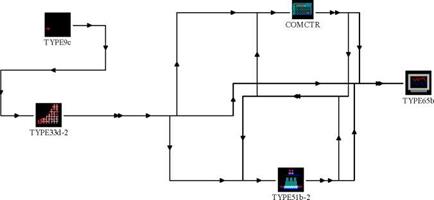
The key component within the TRNSYS model is the cooling tower defined by TYPE 51b. The model is based on determining mass transfer number of transfer units [9]. This parameter is defined by
empirical coefficients which vary widely. In order to validate the cooling tower model, performance data was obtained from the manufacture [8]. Data at low dry and wet bulb conditions, are not readily available, as a result, the cooling tower model was validated against a data set based on standard daytime conditions. Overall, the difference in outlet water temperature was less than 2%.
The TRNSYS model is presented in Fig. 1. A stratified tank (TYPE 4a) is used for thermal storage. The tank height is fixed at 12 m. Section 1 of Fig. 1 represents the simulation of the night time cooling method and section 2 determines the energy balance of the tank. For the simulations, the overall energy balance was less than 1% of the total energy transferred. The control strategy adopted was based on a day time (0700 — 1800) and night time (2100 — 0600) operation. During the night, if the temperature of the top of the tank was greater than the wet bulb temperature, water from this point would be directed to the cooling tower and returned to the bottom of the tank. As specified from the manufacturers, cooling towers are best operated at a constant water mass flow rate to prevent scaling. Therefore the cooling tower was operational for the entire night period at the specified flow rate of
60.5
|
Section 2: J Energy balance |
 |
kg/s. For the designed tank size of 2000 m3, the average approach from the cooling tower was 2 oC. Based on the standard deviation most approach values ranged from 0.6 to 3.4 oC. These values reflect the approaches presented in [3] as well as that presented by the manufacturer’s data [8].
During the day, chilled water was taken from the bottom of the tank only when this temperature was less than 18 oC. Chilled beam systems are controlled through variable flow [1]. Therefore under different load conditions, the mass flow rate was determined based on the load from Eqn. (1). The return temperature from the chilled beam was fixed at 21 oC as specified in [1].
A second TRNSYS model (Fig. 2) was developed in which the cooling tower was used to meet the condensing load from a chiller system during the day. With this arrangement the load was determined using equation 1 and modified by the COP of the chiller. The mass flow rate was constant at 60.5 kg/s and therefore the outlet temperature varied with load.
|
Fig 2. TRNSYS model of a conventional cooling tower system. |
The TRNSYS simulations were run over the entire year with a time step of 1 hour and tolerances maintained at 0.001. The system was modelled with different sized tanks. Fig. 3 shows the proportion of the cooling load achieved using the cooling tower in combination with night time thermal storage for each tank volume. At the minimum volume of 250 m3 a meaningful contribution of 36% of the load was met, at 2000 m3 the contribution was 84% while for a 5000 m3 tank, 97% of the load was provided by the system. This result shows that for many days when cooling is needed the preceding night provides an adequate heat sink for the system. Increasing the tank size reflects storage of many days, with diminishing benefits at larger tank volumes. The contribution values at large tank volumes reflect the impact of a few nights each year where the wet bulb at night is high and insufficient cooling can be achieved for the following day. Overall the results show that a 5000 m3, tank 12 m high which equates to a diameter 23 m, can provide essentially the entire sensible cooling demand of the building.
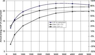
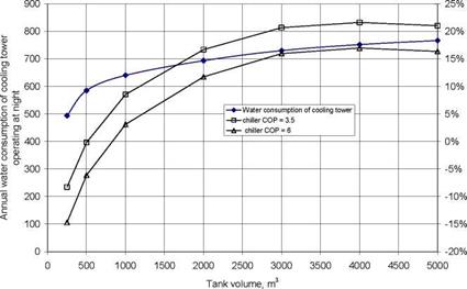
Due to the lower driving potential, a cooling tower operating at night may need to operate for longer, requiring more fan power and use more water. Fig. 4 shows the annual energy based COP of the cooling tower for each tank volume and Fig. 6 shows the corresponding annual water usage of the cooling tower operating at night. The COP was determined by the ratio of the total cooling delivered and the total fan energy used over the year. The additional pumping power required for the night time operation was ignored. From the simulation of the conventional system with the cooling tower operating during the day with a chiller, and ignoring the heat of compression from the chiller system, the COP of the cooling tower was found to be 61 and the annual water consumption was 875 m3.
Overall the COP of the cooling tower shown in Fig. 1 reduced significantly compared to a conventional cooling tower COP, ranging from 12 to 24. However, relative to the COP of a chiller, which ranges from 3.5 to 10, a significant saving can be achieved. Fig. 4 shows the saving which can be achieved with respect to tank volume. To calculate the saving, the cooling demand which could not be met by the proposed system was assumed to be met by a backup chiller with a COP of 3.5. This value was then compared to a conventional chiller system with an annual energy COP of the chiller of 6 as well as 3.5. A lower COP for the unmet load of the proposed system was applied as this load is more likely to occur when the chiller is fully loaded. For most tank volumes a significant energy saving was obtained. For the specified 2000 m3 tank, the saving ranged from 50% to 71%, and savings occurring at a tank volume greater than 500 m3, based on a chiller COP of 6. The energy reductions achievable, particularly at the low tank volumes, are strongly dependant on the COP of the comparative chiller.
|
Tank volume, m3 Fig. 3. The energy contribution of the night time cooling system to the total sensible cooling load. |
A conventional cooling tower removes both the heat from the cooling load and the heat of compression, which is a function of the COP of the chiller. Compared to the water consumption not including the heat of compression of 875 m3, this heat can increase the water consumption by up to 18%, at the lowest chiller COP. Therefore, potential exists for a water saving.
|
Tank volume, m3 |
|
Fig. 5. Water consumption of a conventional cooling tower with various chiller COPs.
|
|
Fig. 6 shows the water saving of the proposed cooling tower system. To determine the total water usage of the proposed system, the water usage of a backup chiller to provide the unmet load was calculated from the data set, based on a chiller COP of 3.5. The water saving, was then calculated against a conventional system operating with a chiller COP of 3.5 and 6. In most cases the water consumption of the proposed system is lower than the water consumption of the conventionally operated cooling tower. The water saving reduces with tank volume and at the low tank volumes, an overall increase in water consumption is observed. However, this is strongly dependant on the COP of the chiller. For the 2000 m3 tank the saving ranges from 12% to 17% with savings achieved at a tank volume greater than 1000 m3, based on a chiller COP of 6. Chiller COP |
A TRNSYS simulation was conducted on a cooling tower driven chilled ceiling system with thermal storage. Overall, the system can readily meet the majority of the load. At the specified tank size of 2000 m3, 84% of the load was met while at 5000 m3, 97% of the load was met. Due to the lower driving potential, the cooling tower was found to operate at a significantly lower COP then when operating conventionally. However, significant energy savings were still achieved with this arrangement. Furthermore, water savings are also achievable. The performance of the system is strongly dependant on the COP of the chiller and the tank volume. For a building with 8000 m2 floor space, savings in energy and water were achieved with a tank volume of 1000 m3. For the specified tank volume of 2000 m3, the saving in energy was at least 50% and the saving of water was at least 12%. For a 5000 m3 the savings of energy and water were at least 69% and 16%, respectively. Consequently, the proposed system has the potential to provide the vast majority of sensible cooling and achieve significant energy and water savings.
[1] M. Virta, D. Butler, J. Graslund, J. Hogeling, E. Kristiansen, M. Reinikainen and G. Svensson (2005). Chilled Beam Application Guidebook, Federation of European HVAC Engineers (REHVA).
[2] F. Alamdari, D. Butler, P. Grigg and M. Shaw, Renewable Energy, 15 (1998) 300-305.
[3] B. Costelloe and D. Finn, Energy and Buildings, 13 (2007) 1235-1243.
[4] F. Bruno (2006). Centralised PCM Systems for Shifting Cooling Loads During Peak Demands in Buildings, Sup. Tech. Paper, Melbourne City Council, Australia.
[5] S. Esmore, Innovative design — Batiso and night sky cooling, Ecolibrium — Journal of the Australian Institute for Refrigeration Air conditioning and Heating (AIRAH), September 2005 (2005) 30-35.
[6] C. Broadbent, Legionella in hot water systems, Ecolibrium — Journal of the Australian Institute for Refrigeration Air conditioning and Heating (AIRAH), April 2003 (2003) 24-29.
[7] AIRAH (2005). AIRAH Handbook, Australian Institute of Refrigeration, Air-conditioning and Heating Inc., Melbourne, Australia.
[8] Aqua — Cool Towers Pty Ltd (accessed 2008), MSS Cooling Tower Specifications, URL://www. aquacooltowers. com. au/.
[9] J. Braun (1988). Methodologies for the Design and Control of Chilled Water Systems, Ph. D. Thesis, University of Wisconsin — Madison.
J.-C. Hadorn
Operating agent Task 32 for the Swiss Federal Office of Energy
Groupe Berney — BASE Consultants SA, Geneva, Switzerland
ichadorn@baseconsultants. com
Abstract
Storage is a key success factor for the large development of solar heat utilisation in mid climate. IEA Solar Heating Cooling Programme started Task 32 in 2003. After 4,5 years Task 32 was completed in December 2007. The main objective of the Task was to contribute to the development of advanced storage solutions in thermal solar systems for buildings that lead to high solar fraction, and up to 100% in a typical 45N latitude climate.
The Task was organised in 4 Subtasks:
1. Subtask A: Evaluation and Dissemination (Subtask Leader: Switzerland / France Thomas Letz)
2. Subtask B: Chemical and Sorption (Subtask Leader : Chris Bales, Sweden)
3. Subtask C: Phase Change Materials (Subtask Leader: Wolfgang Streicher, Austria)
4. Subtask D: Water (Subtask Leader: Harald Drueck, Germany)
and gave valuable results and new information in all aspects of the 4 technologies that were investigated. This paper by the Operating Agent presents an overview of achievements and some of the main results. For detailed presentations of the scientific work, the reader can refer to companion papers from experts who participated in Task 32 and to the http://www. iea-shc. org/ web site.
Keywords: heat storage, cold storage, water tank, PCM, sorption, chemical reaction, solar