Как выбрать гостиницу для кошек
14 декабря, 2021
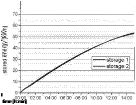
At first, the performance of the storage was determined in standalone tests. For this, a total of 70 charge and discharge cycles were performed and several parameters recorded. Fig. 4 shows typical temperature-time curves at the inlet and outlet of the two storage modules and at two locations in the PCM. Using the volume flow of the heat transfer fluid and its heat capacity, the heating / cooling power were calculated and then by integration over time the stored energy. The left side of fig. 4 shows the results for loading, which is heating the storage modules, the right side for unloading, that is cooling down the storage modules.
The evaluation of the recorded data showed that charging the storage modules latent interval at design temperature 36 °C takes about 10 hours. The measured power at charging with a supply temperature of 36 °C was 11 kW, which is close to the design value of 12 kW. The measured power at discharge with a supply temperature of 22 °C was 10 kW. The extended discharging process (about 12 hours), is caused by the fact that the thermal resistance within the PCM increases with time. The subcooling oft the PCM is about 2 K, and only observed at the start of the discharge process. The integration of the power over time, which gives the stored heat, shows that the storage achieves the design storage capacity of 120 kWh. Further on, the tests showed no degradation of the storage capacity during the 70 cycles.
|
time [h:min] |
|
time [h:min] |
|
time [h:min] |
|
36 о ф 32 =3 го О) 28 E <D 24 20 |
|
outlet storage 1 outlet storage 2 storage 1 storage 2 inlet |
|
8 |
|
6 |
|
00:00 02:00 04:00 06:00 08:00 10:00 12:00 14:00 time [h:min] 10′
|
|
і 4 2 |
|
0 00:00 02:00 04:00 06:00 08:00 10:00 12:00 14:00 time [h:min] time [h:min] |
 |
 |
Fig. 4. Operational results of the two latent heat storage modules. Temperatures (top), power (centre) and
stored energy (bottom) during loading (left) and unloading (right) of the storage modules.
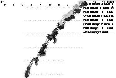
The performance of the latent heat storages depending on the logarithmic mean temperature difference in the latent interval during several charging and discharging cycles is shown in fig. 5 and fig. 6. They show an almost linear relationship, which is caused by the respective thermal resistances and the fact that the measurements were performed while the PCM was in the melting / solidification process.
|
|
OPCM-storage 2 datal PCM-storage 1 datal PCM-storage 2 data2 + PCM-storage 2 data3 ■ PCM-storage 1 data2 + PCM-storage 1 data3 ■PCM-storage 1 data4 |
|
4 |
|
10 |
|
Imtd 11 12 |
 |
Fig. 5. Performance characteristic of both latent heat storages depending on the inlet temperature while
charging.
power [kW]
|
7 — |
|
6 — |
|
5 — |
|
4 — |
|
3 — |
|
2 — |
|
OPCM-storage 2 data1 ■ PCM-storage 1 data1 A PCM-storage 2 data2 OPCM-storage 1 data2 Ж PCM-storage 1 data3 OPCM-storage 2 data3 + PCM-storage 2 data4 ■PCM-storage 1 data4 |
|
0 0 1 2 3 4 5 6 7 |
|
Imtd |
|
9 10 11 12 |
 |
8 1
Fig. 6. Performance characteristic of both latent heat storages depending on the inlet temperature while
discharging.