Как выбрать гостиницу для кошек
14 декабря, 2021
Сегодня каждый, кто собирается в отпуск и не знает, с кем оставить своего котика или кошку, может во[...]
|
public pool |
|
fire station |
|
renovated gym |
The solar assisted district heating system with seasonal thermal energy storage in Eggenstein — Leopoldshafen (Germany) is the first system realized with existing renovated buildings. The project was initiated by a major refurbishment of the school, the gym and the existing district heating system. An additional gym with shed roof carrying 600 m2 of flat plate collectors (FC) was built. Together with a public swimming pool and a fire station the district heating system consists of buildings with a gross building area of 12 000 m2. For seasonal thermal storage of the solar heat produced by 1 600 m2 of flat plate collectors a 4 500 m3 gravel-water thermal energy store (TES) is integrated into the district heating system, see Fig. 1.
|
600 m2 FC |
 renovated school
1000 m2 FC
new gym
gravel-water thermal
energy store
Fig. 1: Solar assisted district heating system with 1600 m2 flat plate collectors and seasonal storage in
Eggenstein-Leopoldshafen (Germany
For backup heating two 600 kW gas boilers and a 30 m3 buffer store are available. Discharging of the seasonal TES down to 10 °C is facilitated by the use of a heat pump with a thermal power of 60 kW. Thus, the thermal capacity of the store is increased by 75% compared to discharging of the heat store to a return temperature of the heating net of 40 °C.
A detailed description of the system concept is given in [1]. Furthermore, optimization of the solar assisted district heating system by means of TRNSYS simulations is presented in [2]. This paper focuses on the design and construction of the gravel-water store and the measurement concept of the system.
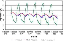
The effect of the PCM during winter season was evaluated in the experimental set-up during a free — floating temperature test. Fig. 11 shows the outside ambient temperature and the inside ambient temperature of the brick cubicles and Fig. 12 presents the data for the alveolar brick cubicles.
In the second week of December the temperature was very low, never reaching 15 °C (Fig 11a). The inside temperature in the RT27-PU cubicle follows the same tendency as in the PU cubicle with a higher absolute value. At the beginning of the week the temperatures were almost the same but the difference increased to 0.4 °C at the end of the week. Similar results were observed in January, February and March (Fig. 11b to Fig. 11d) with temperature differences around 0.3 °C, especially during the cold hours of the day. This effect can be caused by the low thermal conductivity of the PCM (0.2 W/mK), which works as insulation.
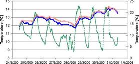
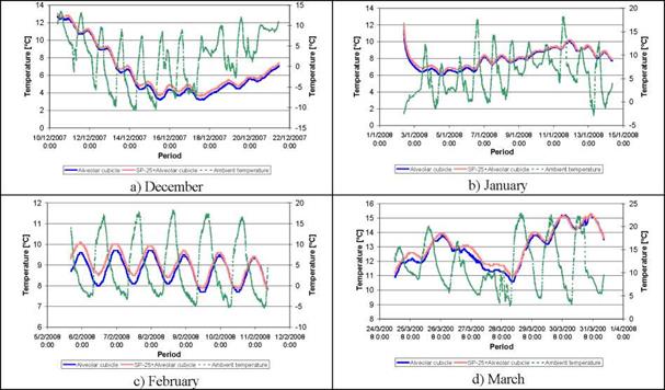
Referring to the alveolar brick and PCM-alveolar brick cubicles, Fig. 12a presents the data of the outside and inside temperatures during the second week of December. A similar effect as in the brick cubicles is observed. Although the temperature of both cubicles presents the same tendency, the SP25- alveolar one is between 0.1 °C and 0.5 °C warmer than the alveolar. Similar results are obtained for January, February and March (Fig. 12b to Fig. 12d). In those cases the effect in more visible at the beginning of the week and decreases with time.
|
15 10 5 Е ш 3 0 ш а. -5 I- -10 -15 |
![]()

|
PU cubicle |
![]()
|
c) February Fig. 11 Comparison of the inside temperatures of PU and RT27-PU cubicles. |

RT-27+PU cubicle — — — Ambient temperature |
a) December
|
|
b) January
|
|
8 0:00 8 0:00 8 0:00 8 0:00 8 0:00 8 0:00 8 0:00 8 0:00 0:00
Period
I PU cubicle………………………. RT-27+PU cubicle ■ • ■ Ambient temperature]
d) March
SHAPE * MERGEFORMAT

|
In this work the benefits of using PCM in conventional and alveolar brick construction are studied. Both free-floating temperatures and energy consumptions are analyzed for summer and winter periods.
During summer period, a reduction of the energy consumption of the HVAC system was achieved for set points higher than 20 °С. When the set point was reduced the PCM effect decreased since it is not melting properly.
The experimental results of the winter period showed a positive effect of the PCM. The increase of the insulation effect introduced by the PCM results in higher temperatures in the cubicles, especially during the cold hours of the day.
The work was partially funded with the project ENE2005-08256-C02-01/ALT, the project 2005SGR 00324 and with a collaboration with the companies Synthesia, Honeywell, Gremi de Rajolers,
Hispalyt, Tealsa, Europerfil, Prefabricats Pujol, Prefabricats Lacoma, Ceramicas Sampedro and Cityhall of Puigverd de Lleida.
Marc Medrano would like to thank the Spanish Ministery of Education and Science for his Ramon y Cajal research appointment.
[1] I. O. Salyer, A. K. Sircar, R. P. Chartoff, D. E. Miller, Advanced phase change materials for passive solar storage applications, in: Proceedings of the 20th Intersociety Energy Conversion Engineering Conference, Warrendale, PA, USA, (1985), pp. 699-709.
[2] M. Shapiro, D. Feldman, D. Hawes, D. Banu, PCM thermal storage in drywall using organic phase change material, Passive Solar Journal 4 (1987) 419-438.
[3] D. Banu, D. Feldman, F. Haghighat, J. Paris, D. Hawes, Energy-storing wallboard: flammability tests, Journal of Materials and Civil Engineering 10 (1998) 98-105.
[4] A. M. Khudhair, M. M. Farid, A review on energy conservation in building applications with thermal storage by latent heat using phase change materials, Energy Conversion and management 45 (2004) 263-275.
[5] B. Zalba, J. M. Marin, L. F. Cabeza, H. Mehling, Review on thermal energy storage with phase change: materials, heat transfer analysis and applications, Applied Thermal Engineering 23 (2003) 251-283.
[6] A. Hauer, H. Mehling, P. Schossig, M. Yamaha, L. F. Cabeza, V. Martin, F. Setterwall, International energy agency implementing agreement on energy conservation through energy storage, Annex 17 Final report, 2005.
[7] L. F. Cabeza, C. Castellon, M. Nogues, M. Medrano, R. Leppers, O. Zubillaga, Use of microencapsulated PCM in concrete walls for energy savings, Energy and Buildings 39 (2007) 113-119.
On account of the aforementioned reasons, the implementation of predictive control (i. e., control taking into account estimates of future loads or conditions) is highly advisable in a house with active and passive storage capacities, such as the ANZEH. At the present time, predictive control is facilitated by the availability of reliable and complete weather forecasts.
To study the response of the ANZEH under different conditions, artificial sequences of 5 days, attempting to represent typical series of cloudy and sunny days, were designed. In these sequences, a sunny day was assigned a daily clearness index (KT) of 0.7, an intermediate day was assigned a KT of 0.5, and a cloudy day was assigned a KT of 0.3. The model of Liu and Jordan, as described in
[5] , was used to determine a typical distribution of hourly clearness indexes (kT) for both conditions. The Erbs model [5] was used to calculate the diffuse fraction of the global horizontal radiation. Finally, the Perez model [6] was used to calculate radiation on surfaces with different orientations.
In the sequences of 5 days used in this study, the last two days were assumed to be cloudy, while the first three days can be either cloudy (represented by a C), intermediate (represented by an M) or sunny (represented by an S). These sequences can be applied to any five consecutive days in the year. After choosing an initial day (from 1 to 365) astronomical angles can be taken into account. The graphs below correspond to the days from January 15th to January 19th.
|
Figure 4. Global Horizontal Radiation corresponding to scenarios SCCCC, SCSCC and SSMCC. |
|
day |
 |
 |
Temperatures for Montreal were modelled using a steady-periodic curve using an average value and average fluctuation range for the corresponding month, and the design day data (quasisinusoidal) proposed by ASHRAE [7]. Wind speed data from a TMY2 (TRNSYS typical meteorological file) [8] corresponding to the dates examined, was used.
day day
4.3 Tank charging, space heating, and ventilation
The tank will only be charged when the top tank temperature is below the setpoint. For all cases, the HX is used directly if the BIPV/T air temperature is at least 3 degrees above the top tank’s temperature. If this is not the case, but the BIPV/T air temperature is above 10 °C, then both heat pumps are used to charge the tank. If the temperature is between 3.5 and 10 °C, then only one heat pump is used. Finally, if the BIPV/T air temperature is below 3.5 °C, one heat pump is turned on using the ground as a source. If the temperature in the house is too high (28.0), then the ventilation rate will be increased from 0.3 ACH (including natural and mechanical ventilation) to 1 ACH per hour.
HMOUDA Imen1*, RODRIGUEZ Ivette2 and BOUDEN Chiheb1
1Energy in Buildings and Solar Energy, National School of Engineers of Tunis
ENIT B. P. 37 1002 Tunis — Belvedere Tunisia
2Centre Tecnologic de Transferencia de Calor (CTTC), Universitat Politecnica de Catalunya (UPC), C.
Colom 11, 08222, Terrassa, Barcelona, Spain
Corresponding Author e-mail : ih tn@yahoo. fr
|
C (ARa) І4т |
|
as @a(T) = exp |
|
1, where T the dimensionless time, A the aspect ratio of the vertical |
Thermal energy storage tank is an essential component of solar heating systems. In this process, the buoyancy convection plays an important role where it is essential to ensure the availability of energy at the following days. Long-thermal behaviour of cooling an initially isothermal Newtonian fluid in a vertical cylinder by unsteady natural convection has been investigated in this study by scaling analysis and direct numerical simulation. The studied case assumes that the fluid cooling is due the imposed fixed temperature on the vertical side wall where as the top and bottom boundaries are adiabatic. Transient, axi-symmetric and natural convection in storage tank is studied. The unsteady natural convection has been investigated numerically by mean of an appropriate CFD code developed and validated using different benchmarking cases. The long-term behaviour of the fluid cooling in the cylinder is well represented by the average fluid temperature function of time, and the average Nusselt number on the cooling boundary. The scaling analysis shows that the dimensionless temperature is related to the dimensionless time, the Rayleigh number and the aspect ratio of the vertical cylinder. The dimensionless temperature ejj) is scaled
cylinder, Ra the Rayleigh number, and C a proportionality constant. A series of direct numerical simulations with the selected values of A, Ra, and Pr (Pr is the Prandtl number) in the ranges of 1/3< A <3, 6.106< Ra < 6.1010 and 1< Pr <1000 have been carried out to validate the developed scaling relations, and it is found that these numerical results agree well with the scaling relations. The numerical simulations reveal that the flow has considerably different transient features and vigorous flow activities mainly occur in the vertical thermal boundary layer on the side wall.
Key words: CFD, natural convection, cooling-term.
The phenomenon of laminar convection in fluids in a cylindrical enclosure, driven by density difference, often occurs in technical applications and industrial processes. The fluid motion caused by this phenomenon has a great impact on the working characteristic of devices and processes where it occurs. This problem arises in applications such as: tanks for energy storage. Indeed, buoyancy convection plays an important role in process of thermal energy storage where it is essential to ensure the availability of energy at the following days. Thus, the system response to changing boundary conditions and the understanding of its behavior is of fundamental interest and practical importance.
Several works concerning this subject are available in the literature, involving experimental and numerical analysis. Cotter and Charles [1-2], in two papers, investigated, during the cooling
*
process, the transient natural convection of a warm crude oil contained in a vertical cylindrical tank. The numerical results have been compared with experimental data and a time dependence of Nusselt number for several oil viscosity has been defined. Natural convection was also analyzed by Ivancic et al. [3]. They investigated the case of the cylindrical tank using an adiabatic sidewall while maintaining low temperature at the top and high temperature at the bottom. Different tank aspect ratios (1 — 5) and Prandlt number (10-2 — 105) have been examined.
Oliveski et al. [4] made a numerical and an experimental analysis of velocity and an temperature fields inside a storage tank submitted to natural convection. They studied the effect of aspect ratio, volumes and insulation thicknesses on the thermal performance of the storage tank. Correlations for the Nusselt number were obtained. A good agreement between the numerical and experimental results have been obtained. Adopting the same methodology, these authors [5], compared the onedimensional results with detailed model and experimental results. They shown that simplified model can agree with experimental only when several computational artifices were included.
In [6], [7], the authors carried out a scaling analysis and direct numerical simulation of the transient processes of cooling-down an initially homogeneous fluid by natural convection in a vertical cylinder. Many direct numerical simulations under different flow situations in terms of Ra, Pr and A were studied. The results show that vigorous flow activities concentrate mainly in the thermal boundary layer along the sidewall.
More recently, Rodriguez et al. [8] carried out a scaling analysis and numerical simulation of transient process of cooling-down an initially homogeneous fluid in a vertical cylinder submitted to natural convection. The obtained correlations can be extrapolated to other situations as they are expressed in term of non-dimensional parameters governing the phenomenon that occurs inside the tank.
In this work, a long-term cooling process of a storage tank submitted to unsteady natural convection is numerically investigated. The the top and upper walls of the stoarge tank are supposed adiabatic while the sidewall is submitted to ambient temperature. A series of numerical simulations with the selected values of A, Ra, and Pr (Pr is the Prandtl number) in the ranges of 1/3< A <3, 6.106< Ra < 6.1010 and 1< Pr <1000 have been carried out to validate the developed scaling relations.
|
and |
|
1 |
|
^eoSeo |
|
1 |
|
h |
|
co co |
|
(14) |
|
(15) |
|
Zi |
|
Z |
|
9 |
Zi and Z9 The thermal resistance between the heat source and the external surface of the evaporator and between the external surface of the condenser and the heat sink respectively are given by
|
evaporative and |
 Z2 and Z8 are the thermal resistances across the thickness of the tube wall in the the condenser respectively, which is determined as
Цр./р,)
2nlek
and
|
(17) |
![]() 7 = ln(D,/D)
7 = ln(D,/D)
8 2nlck
2.2.1 Internal resistant.
|
Z3p = |
|
______ 1______ Ф3д°’20°’4 (iDLe)0-6 |
|
(18) |
Z3 and Z7 are the internal resistances due to pool and film boiling of the working fluid which is divided into Z3p is resistant from pool boiling:
Z3f is resistant from film boiling at the evaporator section :
Z = CQ13
3f " Бі4/У/3ЬєФ 24/3 (19)
when g is gravity (m/s2)
C is constant of cylinder tube C = (1/4)(3/n)43 = 0.235
Ф2 is Figure of Merit:
|
(20) |
![]() ( 3 2 у ‘ "
( 3 2 у ‘ "
Lkl Pl
,l
L is Latent heat of working fluid (kJ/kg)
kl is thermal conductivity of working fluid as liquid phase (W/moC) pl is density of working fluid as liquid phase (kg/m3)
, is viscosity of working fluid as liquid phase (N/m)
|
: Ф |
|
3 |
|
= 0.325 x |
|
0.5^0.3~ 0.7 pl kl Cpl p 0.25, 0.4,, 0.1 pv L Ul |
|
(21) |
|
0.23 |
 |
||
Ф3 Figure of Merit (3)
Cpl is the specific heat at constant pressure of working fluid as liquid phase (kJ/kgoC)
pv is the density of working fluid as vapor phase (kg/m3)
Pv is the vapor pressure of working fluid (Pa)
Pa is the atmospheric pressure 101.3 kPa and the condition for using Z3p and Z3f as Z3 is if Z3p > Z3f so
Z3 = Z3p
if Z3p < Z3f so
Z3 = Z3PF+Z3f(1-F) (22)
when F is the filling ratio that is defined by
Vi
|
F = |
|
(23) |
ALe
Vl is the volume of working fluid (m3)
A is the area cross section of the pipe (m2)
|
Z7 |
|
(24) |
|
CQ1/3 g1/3LcФ |
|
4/3 2 |
Z7 is the resistance from film boiling of working fluid at the condenser section
Z4 and Z6 are the thermal resistances that occur at the vapor liquid interface in the evaporator and the condenser respectively. These are always neglected, being exceedingly small.
Z5 is the effective thermal resistance due to the pressure drop of the vapor as it flows from the evaporative to the condenser. It is small compared to Z3 and Z7.
Z10 is the axial thermal resistance of the wall of the container. This is always neglected, being exceedingly small. Due to Z4,Z6,Z5 and Z10 always being neglected because of being exceedingly small, thus the overall thermal resistance is approximated by
|
(25) |
![]() Ztotal = Z1 + Z2 + Z3 + Z7 + Z8 + Z9
Ztotal = Z1 + Z2 + Z3 + Z7 + Z8 + Z9
In order to investigate the potential of solar thermal technologies at a residential scale in Wales, average weather data for the city of Cardiff is used in the simulations. The data used is in TMY2 format and is provided by the weather library of TRNSYS. The TMY2 average year for Cardiff is built in METEONORM, based on measurements from a local weather station [7]. Fig 1 shows the difference between predictions using 30 year average data and the weather data built in
|
Fig 1. Incident (direct and diffuse) solar energy curves (10m2 collector, 45° tilt South) with ECOTECT data and with 30 year average values given by Page and Lebens. |
 |
METEONORM. The values represent the incident solar energy on a 10m2 surface orientated towards south and tilted for 45o in Cardiff calculated with the TMY2 weather data and with average weather data of the years 1941-70[8]. To represent the variations found in real weather conditions, one year data for Cardiff taken from actual measurements from a weather station located at the roof of the Welsh School of Architecture [9] during year 2007 is also used in this study.
C. Bales1*, P. Gantenbein2, D. Jaehnig3, H. Kerskes4, M. van Essen5, R. Weber6, H. Zondag5
1Solar Energy Research Center SERC, Hogskolan Dalama, 78188 Borlange, Sweden
2SPF Hochschule fur Technik Rapperswil, Oberseestr. 10, CH-8640 Rapperswil, Switzerland
3AEE INTEC, Feldgasse 19, A-8200 Gleisdorf, Austria
4ITW, Pfaffenwaldring 6, D-70550 Stuttgart, Germany
5Energy research Centre of the Netherlands (ECN), P. O. box 1, NL — 1755 ZG Petten, The Netherlands
6EMPA Duebendorf, Abteilung Energiesysteme / Haustechnik, Ueberlandstrasse 129, CH-8600 Duebendorf,
Switzerland
* Corresponding Author, eba@du. se
Abstract
Six main groups have studied chemical and sorption storage within IEA-SHC Task 32 “advanced storage concepts for solar and low energy buildings”. Closed and open adsorption systems, two and three phase absorption as well as chemical storage have been studied. The main results of the work are: identification of potentially suitable materials for long term storage of solar heat and publication of material properties; development of new concepts of short and long term storage of solar heat to prototype stage with lab and field tests; development of models for simulation of chemical and sorption storage; simulation of three systems with long term chemical or sorption storage with the Task 32 boundary conditions; and support in the commercialisation of a chemical heat pump with short term thermal storage for solar heating and cooling applications. The main conclusion from the work is that there are a number of promising technologies and materials for seasonal storage of solar heat for single families but that a lot of research is required before it can be become practical and economical.
Keywords: Solar heating, thermal energy storage, sorption, chemical heat storage
Task 32 of the International Energy Agency’s Solar Heating and Cooling Programme has studied advanced storage concepts for solar and low energy buildings over the period 2004-2007. The Task was split into four subtasks covering the following areas: evaluation and dissemination (A), chemical and sorption storage (B), Phase Change Materials (C) and advanced water storage (D). This paper describes the work performed in Subtask B on chemical and sorption storage, including results from basic research in terms of material and heat transfer characteristics, as well as store and system modelling.
Six groups have been active in this Subtask, as shown in Table 1 below, which also shows the type of technology that the groups have studied. EDF from France have also participated with work on chemical storage towards the end of the Task. The scope, in terms of general system aspects, for Subtask B was the same as that for the whole of Task 32, namely solar heating and cooling systems for residential buildings, principally detached houses for one up to a few families. Buildings with a larger specific heat load (>100 kWh/m2 for Zurich climate) were not considered. The main focus was to be storage solutions sized to achieve a significant solar fraction. In terms of temperature, the
storage solutions have been limited to temperatures < 250°C, with the emphasis on materials suitable up to around 150°C.
The scope in terms of storage concepts included chemical reactions and thermo-chemical storage, which was in practice restricted to sorption processes, both adsorption and absorption. Only one storage solution dealt with in Subtask B has become commercial within the time frame of Task 32, that developed by the Swedish company ClimateWell from Sweden, with over 35 stores/heat pumps having been sold, mostly for solar heating and cooling systems in Spain. A demonstration system of a closed adsorption store was made in the Modestore project, but the materials available for the field test were shown to be not suited for seasonal storage. Three other projects have got as far as design and testing of lab prototypes of sorption stores, and the sixth project was at the stage of material characterisation.
10 reports from the work on chemical and sorption storage are available from Task 32 website at www. iea-shc. org/task32, along with a number of reports on the work on phase change materials, advanced water stores and methods and intercomparisons.
|
Table 1. Research groups participating in IEA-SHC Task 32’s work on sorption and chemical storage.
|
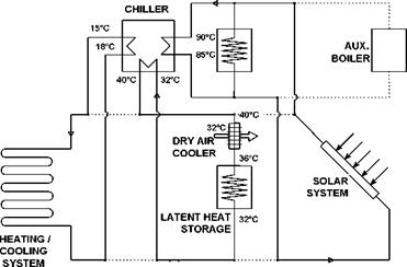
The system layout for cooling in summer shows fig. 1.
|
Fig. 1. System layout for cooling / heat rejection in summer. |
The solar collector field, additionally buffered by a hot water heat storage, drives the single-stage absorption chiller. The chiller has a design-point COP of about 0.7 and a capacity of about 10 kW. Consequently, about 14 kW driving heat are needed as input and about 24 kW must be released as reject heat. In the pilot installation, the new latent heat storage is used in combination with a dry cooling tower. About 50 % of the waste heat should be rejected using the dry air cooler directly in day time. The other 50 % are intermittently stored in the LHS for a duration of 10 hours and rejected using the dry air cooler at night. The night time air temperature is crucial: for Munich it should be below 18 °C most of the summer days. The respective storage boundary conditions including inlet and outlet temperatures are summarized in table 1.
Table 1. Storage boundary conditions for cooling.
|
Storage of reject waste heat in daytime / summer season |
||||
|
Tin [°C] |
Tout [°C] |
Power input [kW] |
Duration [h] |
Storage capacity [kWh] |
|
36 |
32 |
12 |
10 |
120 |
|
release of stored waste heat in night time / summer season |
||||
|
Tin [°C] |
Tout [°C] |
Power output [kW] |
Duration [h] |
Storage capacity [kWh] |
|
22 |
25 |
10 |
12 |
120 |
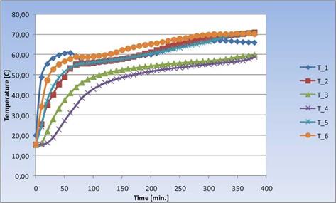
A schematic of the experimental test facility is depicted in Fig. 2. Inside the tank, two piping sections are submerged — one for the hot water from the simulated solar system (an electrical water heater), and one for the water from the simulated load (a mechanically cooled water system). The two sections are arranged for a counter flow regime. Flow rates and temperatures of the water inlets and outlets were measured and recorded, along with temperature readings from six thermocouples distributed inside the tank covering the tank diameter. This six tank temperatures were used to analyze the progress of the charging/discharging process in the melting/freezing PCM.
3.2. Results — charging
During charging the temperature and flow rate from a simulated solar heat source was set to a constant value. Below, example charging curves are shown in Fig. 3 where the charging temperature was 75 °C and the flow rate 0.2 m3/h. The figure shows the accumulated energy [kWh] over time (red curve with square symbols), as well as how the power [kW] varied over a charging cycle (blue curve with diamonds).
|
Fig. 2. The Schematic of the Experimental Test Facility. |
 |
Fig. 3. Example charging curves for PCM HEATPACK prototype (charging temperature 75 °C, and flowrate 0.2
m3/h).
In this particular case, over 14 kWh of heat had been charged after 380 minutes. Initially, the power is high due to a large temperature difference (PCM is at room temperature), and relatively high heat
transfer rate at the beginning of the melting cycle. However, the power then drops off to approximately 2 kW, corresponding to a specific power of 14 kW/m3 storage. The drop below 2 kW in power shown in this case is due to a temporary loss in temperature from the heat source (hot water heater).
To further examine the charging process, the temperature profiles within the tank were examined in more detail by evaluating temperature measurements from thermocouples submerged in the tank throughout the diameter of the storage. These profiles are shown in Fig. 4.
|
Fig. 4. Example temperature profiles within storage during charging of PCM HEATPACK prototype (charging temperature 75 °C, and flowrate 0.2 m3/h). |
As shown, most of the PCM is molten (temperature reading above 58 °C), however for the parts furthest away from the hot water inlet (T_3 and T_4 thermocouples) the melting temperature is not reached until after 300 minutes.
For seasonal storage of thermal energy several concepts have been realized within the last 30 years, see Fig. 2. At least one of each concept has been realized in Germany. Pit TES are constructed without further static means by mounting insulation and a liner in a pit. According to their storage medium seasonal pit TES are distinguished into gravel-water (GW) TES, soil/sand-water TES (SW) or hot water TES.
The hot water (pit) TES is preferable over the gravel-water TES in terms of thermal capacity and operation characteristics. Due to the improved dynamic behaviour compared to the other seasonal TES types, the integration of a hot water TES into the heating system is less problematic, i. e. no additional buffer store is required. In case of leakage, a hot water store may be repaired, whereas — depending on required maintenance and repair — it may be more economic to build a new gravel — water pit TES instead of repairing it.
Gravel — or soil/sand-water TES are only advantageous, if static concerns are of major importance as in the case of the gravel-water TES in Chemnitz, where a parking lot has been built on top of the store. A cover for a hot water TES with comparable static characteristics requires enormous technical and financial efforts. For hot water stores three types of covers may be distinguished, namely self-supporting (shell shaped) covers, supported covers and floating covers, see [3], [4].
For optical reasons, seasonal TES are buried or at least partially buried. Integration into the landscape is of major importance especially as in most cases a seasonal TES will be located within or close to residential areas. Several disadvantages result from the construction below surface level. First of all additional costs arise for the excavation. Secondly, due to the soil pressure, the static requirements are more complex. Furthermore, a construction in moist soil requires measures that prevent the insulation from getting wet. Above ground, a construction with rear ventilation would be a possible solution.
Buried TES may be constructed as cuboids, cylinders, as inversed (and truncated) pyramids or cones or as a combination of one of these geometries. Minimization of thermal losses requires optimization of the area to volume ratio. Additionally, an aspect-ratio of h/d = 1 should be aimed for seasonal storage.
The geometry of tank TES, constructed with in-situ concrete or with prefabricated elements, is more flexible than that of pit TES. The pit geometry is restricted to certain slope angles depending on the friction coefficient of the soil. Furthermore, the depth of the pit may be limited due to ground water. Steeper slopes or construction in ground water can be realized by applying special geotechnical works, such as sheet wall or bore pile wall. Earth works, however, contribute significantly to the total construction costs.
![]()
The decision for a certain concept depends on the geological and hydrological conditions in the bedrock of the respective location. Eventually the costs have to be minimized. For the determination of the costs, transient system simulations are required.
The wall of a buried TES is an assembly of several layers. The complexity of the design of such a composite wall arises due to the fact that the envelope has to guarantee protection of the thermal insulation from moisture penetration. Desiccation must be possible for the case the thermal insulation becomes wet.
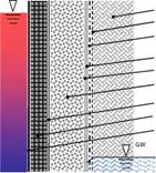
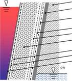
|
soil protective fleece (optional) drainage (labyrinth-like polymer core with filter layer on outer or on both sides) diffusive layer, welded or adhesive bonded (lost) form work (or geocontainer / geobag) thermal insulation (expanded glass or clay granules, foam glass gravel) vapour barrier (optional) concrete, reinforced liner: stainless steel, compound or polymer |
|
soil concrete or steel, according to special geotechnical method drainage (labyrinth-like polymer core with filter layer on outer or on both sides) diffusive liner, welded or bonded protective fleece (optional) thermal insulation (expanded glass or clay granules, foam glass gravel) (lost) form work (or geocontainer / geobag) protective fleece (1200 g) liner: stainless steel, compound or polymer |
 |
 |
The envelope of a buried seasonal TES is a composite consisting of several layers. The most important components are the liner with or without vapour barrier and the thermal insulation (see Fig. 3). Furthermore, several geosynthetics such as geogrid, geonet, drainage grid and (protective) fleece are part of the envelope.
Fig. 3. Multilayered (composite) wall of a seasonal TES, left: tank, insulation inside with respect to the concrete/steel structure; right: pit, insulation outside with respect to concrete/steel, GW: ground water
On the present market high temperature (>80°C) liner materials are not available. Hence, standard geomembranes known e. g. from landfill constructions had to be used for the lining of the store. Several materials were utilized as liner. The most common are (stainless) steel, polymers such as polyolefines (HDPE, LDPE, PP) and elastomers (EPDM, IIR). But also bitumen, clay, resin, high performance concrete and asphalt were considered and/or applied in research and pilot projects.
The majority of the tank TES are sealed with (stainless) steel liners, which are advantageous with respect to temperature resistance, aging and permeation resistance, but have the highest costs. Only the very first Swedish stores, Studsvik and Lombohov, and the TES in Lisse have elastomeric (HR) or polymeric liner (HDPE), respectively. The majority of the pit TES were sealed with HDPE liners, but also PP, EPDM and TPE were applied.
|
Table 1. Lining of pilot and research TES, see [3]
|
Due to the required pressure resistance and temperature resistance (up to 95°C), the application of polymeric insulation materials is limited, nevertheless it was applied in several projects.
Whereas in earlier projects, such as in Lombohov (S), Vaulruz (CH), Friedrichshafen (D), Chemnitz (D) or Sjokulla (FN) sheets of rock or mineral wool, polyurethane (PUR), extruded (XPS) or expanded (EPS) polystyrene were installed at the side walls and on the cover, the more recent TES such as in Hannover (D), Steinfurt-Borghorst (D), Munich (D) or Eggenstein — Leopoldshafen (D) are insulated with bulk insulation material i. e. expanded glass granules or foam glass gravel.
|
Table 2: Thermal insulation of pilot and research TES, see [3]
|
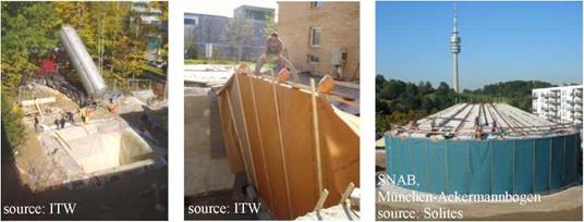
Particularly for large TES (~2000 m3), installation of bulk material by pouring or by air-injecting from silo trucks (see Fig. 4) is much more effective with regard to costs and time than mounting insulation sheets or plates. This is particularly true if costs for scaffolding can be avoided.
Depending on insulation material, operational mode and local boundary conditions, the insulation is built in layers with a thickness of up to 1 m. The thermal resistence of porous materials decreases with increasing moisture content and temperature. Already for dry insulation materials an increase of 30 % of the thermal conductivity at a temperature of 80 °C compared to 20 °C can be observed. This effect is more pronounced with wet insulation, see [5].
|
Fig. 4: Bulk insulation material in membrane-formwork with diffusible liner |