Как выбрать гостиницу для кошек
14 декабря, 2021
Сегодня каждый, кто собирается в отпуск и не знает, с кем оставить своего котика или кошку, может во[...]
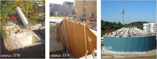
For seasonal storage of thermal energy several concepts have been realized within the last 30 years, see Fig. 2. At least one of each concept has been realized in Germany. Pit TES are constructed without further static means by mounting insulation and a liner in a pit. According to their storage medium seasonal pit TES are distinguished into gravel-water (GW) TES, soil/sand-water TES (SW) or hot water TES.
The hot water (pit) TES is preferable over the gravel-water TES in terms of thermal capacity and operation characteristics. Due to the improved dynamic behaviour compared to the other seasonal TES types, the integration of a hot water TES into the heating system is less problematic, i. e. no additional buffer store is required. In case of leakage, a hot water store may be repaired, whereas — depending on required maintenance and repair — it may be more economic to build a new gravel — water pit TES instead of repairing it.
Gravel — or soil/sand-water TES are only advantageous, if static concerns are of major importance as in the case of the gravel-water TES in Chemnitz, where a parking lot has been built on top of the store. A cover for a hot water TES with comparable static characteristics requires enormous technical and financial efforts. For hot water stores three types of covers may be distinguished, namely self-supporting (shell shaped) covers, supported covers and floating covers, see [3], [4].
For optical reasons, seasonal TES are buried or at least partially buried. Integration into the landscape is of major importance especially as in most cases a seasonal TES will be located within or close to residential areas. Several disadvantages result from the construction below surface level. First of all additional costs arise for the excavation. Secondly, due to the soil pressure, the static requirements are more complex. Furthermore, a construction in moist soil requires measures that prevent the insulation from getting wet. Above ground, a construction with rear ventilation would be a possible solution.
Buried TES may be constructed as cuboids, cylinders, as inversed (and truncated) pyramids or cones or as a combination of one of these geometries. Minimization of thermal losses requires optimization of the area to volume ratio. Additionally, an aspect-ratio of h/d = 1 should be aimed for seasonal storage.
The geometry of tank TES, constructed with in-situ concrete or with prefabricated elements, is more flexible than that of pit TES. The pit geometry is restricted to certain slope angles depending on the friction coefficient of the soil. Furthermore, the depth of the pit may be limited due to ground water. Steeper slopes or construction in ground water can be realized by applying special geotechnical works, such as sheet wall or bore pile wall. Earth works, however, contribute significantly to the total construction costs.
![]()
The decision for a certain concept depends on the geological and hydrological conditions in the bedrock of the respective location. Eventually the costs have to be minimized. For the determination of the costs, transient system simulations are required.
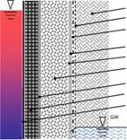
The wall of a buried TES is an assembly of several layers. The complexity of the design of such a composite wall arises due to the fact that the envelope has to guarantee protection of the thermal insulation from moisture penetration. Desiccation must be possible for the case the thermal insulation becomes wet.
|
soil protective fleece (optional) drainage (labyrinth-like polymer core with filter layer on outer or on both sides) diffusive layer, welded or adhesive bonded (lost) form work (or geocontainer / geobag) thermal insulation (expanded glass or clay granules, foam glass gravel) vapour barrier (optional) concrete, reinforced liner: stainless steel, compound or polymer |
|
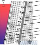
soil concrete or steel, according to special geotechnical method drainage (labyrinth-like polymer core with filter layer on outer or on both sides) diffusive liner, welded or bonded protective fleece (optional) thermal insulation (expanded glass or clay granules, foam glass gravel) (lost) form work (or geocontainer / geobag) protective fleece (1200 g) liner: stainless steel, compound or polymer |
 |
 |
The envelope of a buried seasonal TES is a composite consisting of several layers. The most important components are the liner with or without vapour barrier and the thermal insulation (see Fig. 3). Furthermore, several geosynthetics such as geogrid, geonet, drainage grid and (protective) fleece are part of the envelope.
Fig. 3. Multilayered (composite) wall of a seasonal TES, left: tank, insulation inside with respect to the concrete/steel structure; right: pit, insulation outside with respect to concrete/steel, GW: ground water
On the present market high temperature (>80°C) liner materials are not available. Hence, standard geomembranes known e. g. from landfill constructions had to be used for the lining of the store. Several materials were utilized as liner. The most common are (stainless) steel, polymers such as polyolefines (HDPE, LDPE, PP) and elastomers (EPDM, IIR). But also bitumen, clay, resin, high performance concrete and asphalt were considered and/or applied in research and pilot projects.
The majority of the tank TES are sealed with (stainless) steel liners, which are advantageous with respect to temperature resistance, aging and permeation resistance, but have the highest costs. Only the very first Swedish stores, Studsvik and Lombohov, and the TES in Lisse have elastomeric (HR) or polymeric liner (HDPE), respectively. The majority of the pit TES were sealed with HDPE liners, but also PP, EPDM and TPE were applied.
|
Table 1. Lining of pilot and research TES, see [3]
|
Due to the required pressure resistance and temperature resistance (up to 95°C), the application of polymeric insulation materials is limited, nevertheless it was applied in several projects.
Whereas in earlier projects, such as in Lombohov (S), Vaulruz (CH), Friedrichshafen (D), Chemnitz (D) or Sjokulla (FN) sheets of rock or mineral wool, polyurethane (PUR), extruded (XPS) or expanded (EPS) polystyrene were installed at the side walls and on the cover, the more recent TES such as in Hannover (D), Steinfurt-Borghorst (D), Munich (D) or Eggenstein — Leopoldshafen (D) are insulated with bulk insulation material i. e. expanded glass granules or foam glass gravel.
|
Table 2: Thermal insulation of pilot and research TES, see [3]
|
Particularly for large TES (~2000 m3), installation of bulk material by pouring or by air-injecting from silo trucks (see Fig. 4) is much more effective with regard to costs and time than mounting insulation sheets or plates. This is particularly true if costs for scaffolding can be avoided.
Depending on insulation material, operational mode and local boundary conditions, the insulation is built in layers with a thickness of up to 1 m. The thermal resistence of porous materials decreases with increasing moisture content and temperature. Already for dry insulation materials an increase of 30 % of the thermal conductivity at a temperature of 80 °C compared to 20 °C can be observed. This effect is more pronounced with wet insulation, see [5].
|
Fig. 4: Bulk insulation material in membrane-formwork with diffusible liner |