Как выбрать гостиницу для кошек
14 декабря, 2021
Сегодня каждый, кто собирается в отпуск и не знает, с кем оставить своего котика или кошку, может во[...]
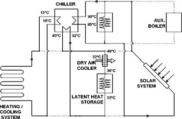
The system layout for cooling in summer shows fig. 1.
|
Fig. 1. System layout for cooling / heat rejection in summer. |
The solar collector field, additionally buffered by a hot water heat storage, drives the single-stage absorption chiller. The chiller has a design-point COP of about 0.7 and a capacity of about 10 kW. Consequently, about 14 kW driving heat are needed as input and about 24 kW must be released as reject heat. In the pilot installation, the new latent heat storage is used in combination with a dry cooling tower. About 50 % of the waste heat should be rejected using the dry air cooler directly in day time. The other 50 % are intermittently stored in the LHS for a duration of 10 hours and rejected using the dry air cooler at night. The night time air temperature is crucial: for Munich it should be below 18 °C most of the summer days. The respective storage boundary conditions including inlet and outlet temperatures are summarized in table 1.
Table 1. Storage boundary conditions for cooling.
|
Storage of reject waste heat in daytime / summer season |
||||
|
Tin [°C] |
Tout [°C] |
Power input [kW] |
Duration [h] |
Storage capacity [kWh] |
|
36 |
32 |
12 |
10 |
120 |
|
release of stored waste heat in night time / summer season |
||||
|
Tin [°C] |
Tout [°C] |
Power output [kW] |
Duration [h] |
Storage capacity [kWh] |
|
22 |
25 |
10 |
12 |
120 |