Как выбрать гостиницу для кошек
14 декабря, 2021
The results presented here correspond to the operation period from June 4th, 2007 to December 1st, 2007. From these 180 days the system was in operation during 108 day. The days without operation were either weekends or days without monitoring data due to a lightning stroke into the data acquisition system. Within these 108 days 1034 hours of operation were registered. In some hours the machine was in operation only a few minutes, but in most of the registered hours a
continuous operation was observed. In Table 1 the number of hours with an operation time within given limits is shown.
|
Operation mode |
Number of hours with an operation time t (in minutes) within the given limits |
||||
|
<15 min |
15<t<30 min |
30<t<45min |
45<t<60 min |
60min |
|
|
cooling |
65 |
23 |
36 |
37 |
282 |
|
heating |
56 |
72 |
28 |
73 |
398 |
|
solar |
39 |
35 |
34 |
26 |
176 |
|
Table 1.Statistics of the operation hours |
![image654 Подпись: to [°C] Fig. 3. Comparison of basic model and experimental results. (a) Ideal and experimental cooling capacity vs. tG (b) Ideal and. experimental COP vs. tG](/img/1154/image654.gif) |
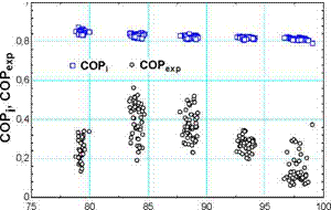 |
Fig. 3 illustrates the comparison of experimental performance parameters with those obtained through the basic model, Eqs. (14) and (15), for 220 test points. The differences observed help identifying the influence of components performance, serving as a diagnosis. In the following, the causes of deviation from the ideal conditions are explained, evaluated and included in the model.
5.1. Influence of components performance. Modified basic model.
The evaporators in this facility layout show low performance [8]. Because of this, part of m ref
supplied to them is not evaporated, but overflows. Therefore, in order to measure the performance of evaporators (fraction of evaporated refrigerant), the cooling capacity obtained if all refrigerant is used in the evaporators Qref is compared with QE exp:
Пе = ; Qref = mref • (hEin — hEo) (21)
Qref
Energy balance in the generator yields:
m = m — m
ref weak strong (22)
The obtained average nE is 50% which is considerably low. With the current design, the excess of refrigerant is not recirculated to evaporators, and therefore it goes to the solution reservoir inside the absorber. Beside this, it has been detected that the distribution of mref (m f and m f) is not symmetrical in some cases, and therefore one of the evaporators runs dry. This situation also explains the low value of qexp and its tendency is not consistent with rise in temperature (Fig. 3). Corresponding values of COPexp show obviously the same behaviour.
Taking into account the evaporators limitations explained above, the modified cooling capacity will be:
4E, mod 4Ei ‘ ПE (23)
The facility performance is also affected by the solution heat exchanger efficiency phex and consequently is considered in the analysis. Beside this, a noticeable difference was identified between solution temperature at generator outlet and separator outlet, as the generation process continued and the refrigerant separation kept on in the path followed by the solution. The temperature drop associated ranged from 4°C to 10°C. The heat transfer associated is called qG.
Then, considering the real efficiency of the solution heat exchanger and the heat transfer losses in the system generator-separator, the modified generation power will be:
qG, mod = qG, i + qhex. i (1 — Vhex ) + qG-sep (24)
As a result, the modified COP becomes:
COPmod = ^mo1 (25)
qG, mod
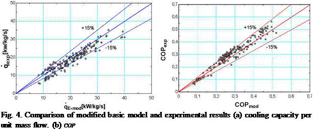
Results obtained incorporating the specific behaviour of components to the basic model can be appreciated in Fig. 4. The predicted cooling capacity and COP shows good agreement with experimental results. This indicates that the main causes of deviation have been included in the model, thus verifying the preliminary diagnosis.
(a) (b)
A facility representing a single effect adiabatic LiBr/water chiller implementing adiabatic absorption facility has been operated under different conditions, corresponding to both design and off-design operational conditions. Performance parameters have been experimentally determined for every test condition.
The differences observed between ideal and experimental results helped to diagnose and identify the influence of components performances on the overall performance of the facility. The
evaluation of the ideal and real cooling powers allowed detecting a low performance of evaporators caused by both dry operation and overflow. Another influence factors which causes the deviation from ideal behaviour are the solution heat exchanger efficiency and the heat transfer losses in the system generator — separator.
Taking into account the particular layout and operation features tested, a good agreement with experimental performance parameters and those obtained through a modified basic absorption model has been achieved. This model incorporates a quantified loss and/or efficiency separating from ideal and has been fitted to experimental data. Experimental results demonstrate the operational possibilities and flexibility of the design, showing a great potential for further work.
The financial support of this study by the Ministry of Education, Science and Technology through CLIMABCAR project DPI 2003-01567, TRANSMACA project DPI 2002-02439 and MINICOM project (FIT 0204-2004-68 and FIT 020100-2003-233), is greatly appreciated. The authors express their gratitude to the technicians of Universidad Carlos III de Madrid Mr Manuel Santos and Mr Carlos Cobos for their invaluable help in this work.
[1] Venegas M., Izquierdo M., Rodriguez P., Lecuona A. Heat and mass transfer during absorption of ammonia vapour by LiNO3-NH3 solution droplets, Int. J. Heat Mass Transfer, 47 (12-13) (2004) 26532667.
[2] Venegas M., Rodriguez P., Lecuona A., Izquierdo M. Spray absorbers in absorption systems using lithium nitrate-ammonia solution, Int. J. Refrigeration, 28 (4) (2005) 554-564.
[3] Arzoz D., Rodriguez P., Izquierdo M. Experimental study on the adiabatic absorption of water vapor into LiBr-H2O solutions, Applied Thermal Engineering, 25 (5-6) (2005) 797-811.
[4] Warnakulasuriya F. S.K., Worek W. M. Adiabatic water absorption properties of an aqueous absorbent at very low pressures in a spray absorber, Int. J. Heat Mass Transfer, 49 (9-10) (2006) 1592-1602.
[5] Elperin T., Fominykh A., Orenbakh Z. Coupled heat and mass transfer during nonisothermal absorption by falling droplet with internal circulation, Int. J. Refrigeration, 30 (2) (2007) 274-281
[6] Wang L., Chen G. M., Wang Q., Zhong M. Thermodynamic performance analysis of gas-fired air-cooled adiabatic absorption refrigeration systems. Applied Thermal Engineering. 27 (8-9) (2007) 1642-1652.
[7] Gutierrez G., Venegas M., Rodriguez P., Izquierdo M., Lecuona A. Experimental characterization of a single stage LiBr-H2O absorption test rig. In Proc. ECOS 2006, Vol. 3, Crete, Greece, July 12-14 (2006) p. 1331-1316.
[8] Gutierrez G., Zacarias A., Venegas M., Rodriguez P. Cooling power evaluation of a water lithium bromide absorption test rig. In Proc. ECOS 2007, Vol. 2, Padova, Italy, June 25 -28 (2007) p. 1183-1190.
Performance of the chiller
In order to evaluate the performance of the chiller a comparison of experimentally measured cooling capacities and COPs with expected values from calculations is shown in Fig. 2. The experimental values were selected according to the following criteria:
1. a continuous operation during the whole hour as well as in the hour before and after,
2. stable temperatures with a small standard deviation has been measures in all three circuits,
3. only cooling operation was considered.
TCooling operation
For the evaluation of the cooling operation only hours with constant and steady operation were considered. Operation periods less than 60 minutes within one hour were not considered in this evaluation in order to avoid effects of transient states. From Table 1 it can be seen that 282 hours could be considered.
B. M. Jones* and S. J. Harrison
Department of Mechanical and Materials Engineering, Queen’s University, K7L 3N6, Kingston, Canada
* Corresponding Author, jones@me. queensu. ca
Abstract
A thermal low-flow liquid-desiccant air handling machine was procured, installed, and field tested. The goal of the present investigation is to evaluate the field performance of the machine and characterize its operation for the temperature range of a solar thermal array. The system studied includes a natural gas boiler supplying the heat, and a cooling tower for heat rejection. System performance was evaluated for the 50 to 90°C temperature range, the operating range of solar thermal collectors. Cooling power varied between 4.3 kW and 22.8 kW for this range of temperature, with a latent heat ratio between 1.1 and 1.9, confirming that the unit is significantly dehumidifying the process air stream. Electrical COP varied between 0.58 and 4.48. Performance data indicates higher temperature solar collectors such as evacuated tube or double glazed flat plat collectors would be optimum in a solar cooling application with this system. These performance figures and methods will be used in future work to simulate and optimize a solar thermal driven dehumidification system for dedicated outdoor air systems.
Keywords: HVAC, Liquid Desiccant, Solar Thermal, Experiment
An effective approach to the problem of latent cooling demand is to decouple the latent and sensible cooling loads. This is accomplished by employing a dedicated outdoor air system (DOAS). A DOAS is designed to precondition the outside ventilation air required for the building by removing the moisture. The remaining sensible load is handled by a conventional AC system in the return air stream, avoiding overcooling and reheat. The conventional electric chiller is put in parallel with the dry outside air stream [1]. This decoupling allows each sub-system to be efficiently designed for the type of cooling load (latent or sensible). Not only does this improve energy efficiency of the overall system, but the system is now able to properly handle a wider range of cooling loads. Figure 1 shows a DOAS configuration, with RA, OA, EA, and SA referring respectively to the Return, Outside, Exhaust, and Supply Air streams.
With increasing importance placed on climate change, energy conservation, energy security, and air quality, the low flow liquid desiccant dedicated outdoor air system driven by solar thermal energy is an attractive technology. It has significant potential advantages over many alternative building energy schemes. The important advantages of the solar thermal low flow liquid desiccant concept are summarized [2-5];
• Sustainable clean solar thermal energy source
• Solar combi-system arrangements possible, increasing solar thermal array usability
• No global warming potential associated with common refrigerants
|
• Low system pressure drop • Zero carryover of corrosive desiccant material • Air cleaning and filtering • Lossless storage of solar cooling power in liquid salt solution
|
Figure 2 is a photograph of the air handling apparatus and the cooling tower. Prominent features of the system are labelled. The primary components of the dehumidification system under investigation include the heat rejection system, the air handling system, and the thermal source system. The process flows for these systems are presented in Fig. 3. The air handling system is a self contained pre-commercial prototype, and includes blowers, pumps, and data acquisition and control equipment. Figure 3 indicates the positions of sensors within the overall apparatus. Sensors are placed such that an energy balance on the sub components can be performed, and to evaluate the performance of the system. An energy balance is calculated for the system components using flow meters and inlet/outlet temperature probes. Table 1 lists the system operational variables provided by the manufacturer and those used in experiment [6].
|
||||||||||||||||||||||||||||||
|
|
O* Blower |
|
|
|
|
|
|
|
|
|
|
|
|
 |
|
|
|
|
|
|
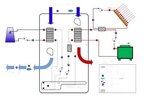

Figure 3 — Process flows and instrumentation
The system was operated over 20 days in July in Kingston, Ontario, Canada. The range of water temperatures expected for a solar thermal application was the primary independent variable. Table 2 is a summary listing of the daily operation of the air handling system under 4 types of regenerator heating profile. The 10th, 13th, and 20th correspond to the 50, 70, and 90°C heating set point. Average conditions for daily operation are listed.
|
Table 2 — Experimental results Day (July 2008)
|
System operation plots for the 25th of July are presented in Figs. 4 and 5. The 25th was operated on a time varying simulated solar heating profile, simulating a 70m2 evacuated tube collector array. Figure 4 is a plot of the conditioner performance for the 25th of July. The system begins operation when the temperature of the solar thermal array reaches 50°C, at 9:30 in the morning. The temperature profile can be seen in the top section of Fig. 4. The temperature profile approaches 80°C as the day progresses and the incident radiation on the simulated vacuum tube collector increases. The temperature profile is adjusted by the programmable logic controller every 30 minutes. From 2, the average cooling rate is 13.5 kW with a latent heat ratio of 1.4. The middle section of Fig. 4 displays the temperature at the process air inlet and outlet. The temperature rises an average of 2.4°C for this day. The bottom section of Fig. 4 shows a significant dehumidification effect, a change in absolute humidity averaging 3.6 g/kg. This amounts to a total absorption of 208.9 kg of water for this day. From the middle section of Fig. 5, it is observed that the absorption and desorption rates are similar. This indicates that the machine is approaching steady state operation even over a varying temperature profile The total amount of water desorbed for this day is 214.1 kg. The bottom section plots the coefficients of performance for this day. The average thermal COP for the 25th is 0.68, the average cooling COP is 0.48, and the average electrical COP is 2.68 for this solar temperature profile.
|
Figure 4 — Conditioner performance under simulated solar load |
|
Figure 5 — Regenerator solar heating profile and system COP’s |
Figures 6 and 7 display the average daily coefficients of performance for the data set. The thermal regeneration COP is the energy of desorbed water divided by the heat absorbed. The cooling COP is the energy change of the air stream divided by the heat absorbed. The electrical COP is defined as the energy change of the air stream divided by the electricity consumption rate, which was 5.5 kW for this system.
Overall, the regenerator COP averaged 0.81 for the days of constant heating temperature operation, while the cooling COP is an average of 0.53. The cooling COP is lower due to the enthalpy gained by the desiccant as it condenses and absorbs water vapor from the process air. The cooling COP can be improved with a higher capacity heat rejection system. The electrical COP can be improved with variable speed drives on pumps and blowers.
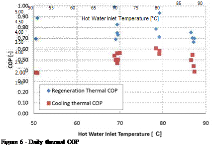 |
Figure 7 — Daily electrical COP
A liquid desiccant air handling system driven by thermal energy was procured. Piping, valves, motors, and thermal sub-components were connected. Transducers included flow meters, thermistors, and relative humidity sensors. Desiccant solution concentration was monitored using a batch process density meter and a density-concentration correlation. A data acquisition system was designed and installed. The system is controlled using a programmable logic controller using relay ladder logic controlling the drive units for pumps and fans, and monitoring system faults. The system commissioning included troubleshooting and government safety inspections.
The system was tested in a field environment. The data set was processed giving enthalpy flows and performance figures for daily operation of the machine. An enthalpy balance on the system was used to check sensors and assumption of adiabatic operation. The assumption of an
adiabatic control volume around the conditioner and regenerator was found to be valid. Regenerator thermal COP was calculated to be 0.76 to 0.99, and conditioner thermal COP was in the range of 0.38 to 0.61 for the entire data set over 50°C to 90°C. Electrical COP increased from 0.58 at 50°C to 4.48 at 90°C. The average latent heat ratio was 1.1, 1.3, and 1.5 respectively for the three temperatures evaluated, showing that the heat load on the conditioner increases as the desiccant is heated in the regenerator. The average cooling power was 4.3, 14.1, and 21.3 kW for the temperature range. Data indicates that high temperature solar thermal collectors would achieve better performance based on their ability to maintain a desired cooling power and their increased electrical COP.
Future work in this project will include coupling a solar thermal array incorporating liquid desiccant storage, and upgrading drive units to improve the system electrical COP.
[1] Mumma, S. A. (2007). DOAS and desiccants Engineered Systems, 24, 37 — 49.
[2] Mei, L. & Dai, Y. (2008) A technical review on use of liquid-desiccant dehumidification for airconditioning application Renewable and Sustainable Energy Reviews, 12, 662 — 89
[3] Hwang, Y.; Radermacher, R.; Al Alili, A. & Kubo, I. (2008) Review of solar cooling technologies HVAC and R Research, 14, 507 — 528
[4] Katejanekarn, T. & Kumar, S. (2008) Performance of a solar-regenerated liquid desiccant ventilation preconditioning system Energy and Buildings, 40, 1252 — 1267
[5] Jain, S. & Bansal, P. (2007) Performance analysis of liquid desiccant dehumidification systems International Journal of Refrigeration, 30, 861 — 72
[6] Lowenstein, A.; Slayzak, S. & Kozubal, E. A zero carryover liquid-desiccant air conditioner for solar applications International Solar Energy Conference, 397 — 407
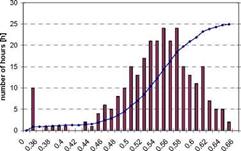
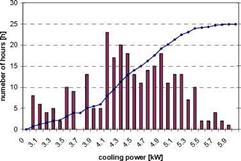
In Fig. 3 and Fig. 4 a histogram of the measured COP and cooling power is shown. COPs between 0.48 to 0.62 were obtained. The measured power shows a much larger dispersion: cooling powers between 3.1 and 5.9kW have been obtained.
![]()
![]()
![]()

 120%
120%
100%
80% « 0) □
60% I"
■o
0)
40%
з
Є
20%
0%
Fig. 3. Frequency diagram of thermal cooling COPs Fig. 4. Frequency diagram of cooling powers. Taking into account the total cold production and heat input over the whole cooling period including hours with on-off behaviour an overall COP of 0.574 with a standard deviation of 0.066 for the hourly values is obtained. The mean cooling power for the hourly values was 4.38kW with a standard deviation of 0.67kW. Nevertheless it is not clear, if this variation of cooling powers is due to a limitation in the capabilities of the chiller or to the requirements of the load. Although the cooling load of the canteen’s kitchen is almost always above 6kW because of the high internal loads, the control system may limit the chillers output power in order to avoid too low inlet air temperatures which may be uncomfortable.
Adsorption constitutes a solid sorption process by which the binding forces between fluid molecules (adsorbate) and the solid medium (adsorbent) derive from an electrostatic origin or from dispersion — repulsion forces. It is an exothermic process as a result of the gas-liquid phase change. The energy liberated during adsorption is called isosteric heat, and it depends on the nature of the adsorbent — adsorbate pair. The theory adopted is the Dubinin-Polanyi theory of volume filling of micropores [2], where the isosteric heat of adsorption can be given as
1.1 Ideal thermodynamic cycle

The adsorption refrigeration cycle consists of two well-defined stages: one is described as the adsorber cooling, with its consequent adsorption process, when the evaporation of the working fluid (the adsorbate) takes place. The other stage consists of the solid medium (the adsorbent) regeneration, when the adsorbate is desorbed and condensed (Fig. 1a). The ideal thermodynamic cycle can be represented by two isosters (isolines with constant adsorbed phase concentration, a) and two intercalated isobars, as shown in Fig. 1b.
The adsorber cooling corresponds to the isosteric process 1-2, depending on the ambient conditions. This process continues until the adsorber pressure reaches its minimum value (point 2), when it becomes equal to the evaporator pressure. At this point, the adsorption process starts and prolongs until its temperature reaches the minimum value (point 3). Then, the adsorber is heated, corresponding to
another isosteric process (3-4), until its pressure reaches a maximum value (point 4). Desorption starts at this point, and goes on until the adsorber temperature reaches its maximum value (point 1), completing, in this way, the cycle.
Figure 3 shows the example of the solar desiccant cooling operation in summer. The collected hot air is used for the regeneration of AHU A and the excessive solar thermal energy is directly exhausted to outdoor. AHU B is operated in dehumidification cooling. Fresh air passed through the foundation pit is cooled to be the air of high relative humidity. The fresh air from the foundation pit is dehumidified by AHU B and is supplied to indoor. When AHU A is finished in regeneration process, AHU A is switched in dehumidification cooling operation and AHU B is switched in regeneration operation. Two set of the solar desiccant cooling system as shown in Figure 3 are installed in the field test office building as shown in Figure 5.

|
Hum 1 |
dity ratio 1 AHU a out — —- 1— 1-4- -.-U — 1- V 1 1 1 1 ҐІ і 1 Lu—1»/ I if |
let in rec — Л*’1| 1 jl 1 |
eneration A г V і Г^ I 111 і і I |
^Hu B outlet in regeneration -U — J — -1— 1— L — 4- — 4- — 1- 1— Qutdoor |
|
1 |
і 1 iv^4—1 i |
1 1 1 1 1 1 —і — + — Iі— I- i і і i |
і і 1 і ^—U |
|
|
и —і — +- 1— L"’l 1 1 1 ‘"71 *T і і і l / l |
||||
|
Ц—і і і і—r і і і і і і і і і і і |
||||
|
1 |
AHU A outlet in dehumidification AHU B, outlet in dehumidification |
|
600 700 800 900 1000 1100 12 00 1300 1400 1500 1600 1700 1800 190C |
|
30 25 20 ^ 15 10 5 |
|
|
|
|
|
|
|
|
|
|
|
|
|
|
|
|
|
|


 250 200 150 100 50 0
C. The supplied air is dehumidified from the outdoor air by the humidity ratio of over 4.6g/kg. The cooling performance of this system was between 4-10 kW from 9:00 to 17:30. About the half of the system performance is occupied by the cooling effect of the foundation pit. Figure 7 shows the fresh air heat load for the EHP without a solar desiccant cooling system. The latent heat load is 68% of total fresh air heat load of 295MJ/day. The fresh air heat load of 73% is processed by the solar desiccant cooling system, because the daily performance of the solar desiccant cooling system is 214MJ/day as shown in Figure 6.
Though the field test space was cooled with both two solar desiccant cooling systems and EHP, the space cooling using EHP only was examined in a week per a month in order to evaluate the performance of the solar desiccant cooling system directly. The field test results for the solar desiccant cooling showed that the reduced daily electric power consumption of the EHP was 36% for the operation of the solar desiccant cooling system compared with the operation stop as shown in Figure 8. Two days when the weather data and the indoor thermal environment conditions were similar were selected to be the direct comparison.
0

![]()
![]()
![]()
![]()

![]()
![]()
![]()
 35
35
25 -40% I
20 15 10 5 0
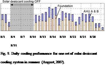
comparison of this system performance. The average of daily cooling performance for the solar desiccant cooling system is 138.6MJ/day in August, 2007. The cooling performance is assumed by twice times in this building, because two set of the solar desiccant cooling system is installed.
3.5. Field test results in winter
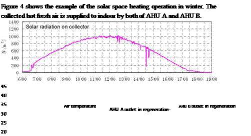
The field test results for the solar space heating showed that the reduced daily electric power consumption of the EHP was 40% for the operation of the solar space heating systems compared with the operation stop as shown in Figure 10. The direct comparison was carried out as like the summer field test.
Millennium Electric T. O.U. Ltd.
P. O. Box 2646, Raanana 43650 Israel
Phone : 972-9-7439490 E-mail : Info@millenniumsolar. com
Abstract
A new innovation technology includes Multi Solar Air Conditioning system using the Multi Solar (PV/T) Collectors System and an Air conditioning unit that using the excessive solar thermal energy produced by the Multi Solar System (MSS).
The basic principle of the Solar Air Conditioning operation:
The hot liquid from the thermal source the MSS collectors enters the air conditioning reactor heat exchanger. Normally the liquid from the MSS Collectors are at least 50oC for charging. This temperature will depend on the power delivered by the solar collectors, which in turn depend on the solar radiation, flow rate and the size and efficiency of the collectors. When the entering heat reaches the reactor heat exchanger, it causes the Li Cl solution in the reactor to boil. When boiling the Li Cl returns to crystalline form. At the same time the water evaporates and steam is released to the condenser/evaporator where it condenses on the heat exchanger with the relatively lower temperature. In some cases, when running the system on solar thermal energy, it is recommended that a back-up thermal source such as a small gas — boiler or a simple electric element be installed in parallel to complement the thermal source in the event of prolonged cold/cloudy periods.
The example below shows the energy balance during charging. Some 44 kWh are required to charge one barrel, giving the heat sink 33 kWh of energy. In winter, this energy can be sent directly to the building distribution system
|
|
It has been mentioned that the technology used for the solar cooling system makes it possible to produce cooling energy in spite of a varying temperature in the solar collector loop, as long as the temperature difference between the input fluid to the absorption heat pumps and the cooling fluid remains above 50°C. For this reason the control system was set to start giving hot water to the absorption heat pumps when the temperature at solar collector output reaches 60°C and while it is above 50°C. This allows the absorption heat pump to start charging up even if at a slow rate, thus making the most of the available solar energy. Then, when fluid temperature reaches 80 to 90°C and considering that cooling water remains below 30°C the absorption process can charge normally. Once at least one out of the four absorption heat pumps installed in Almeria is fully charged, it can start delivering cool water to the cooling coils. Actually, unlike other absorption chillers, the system used in Almeria is discontinuous. That is to say the machine must first charge before being able to deliver the first cooling kWh. When the first charge cycle is completed and the machines start giving cooling energy, a second barrel charges up. This way, when the first barrel goes empty, the charged second barrel takes over and the first barrel can be charged again. This allows for continuous operation as long as the charging rate is higher than the consumption rate of course. However, the system was designed to start charging as soon as possible in the morning so that the absorption heat pump’s barrels would be fully charged by the end of the morning (between 11 and 12h) when active cooling becomes necessary to maintain adequate thermal comfort in the building. On the other hand, the solar array was designed so that charging rate would always be sufficient to ensure continuous operation of the absorption heat pumps.
A solar driven cooling system was presented here, which is one of the first attempts in Spain to integrate a full scale solar cooling system to an office building actually in use. The building is now in its launch phase, so data is not available yet on whether the system is keeping its promises or not regarding energy efficiency. The optimization phase will however be decisive in order to get the system to work to its full potential and achieve the target in terms of energy savings.
P. Hollmuller1* and B. Lachal[13]
1 SESUL / IDL, Universidade de Lisboa, Campo Grande, 1749-016 Lisboa, Portugal
2 Pole en Sciences de l’Environnement, Universite de Geneve, 1227 Carouge / Geneve, Switzerland
* Corresponding Author, pierre. hollmuller@fc. ul. pt
This paper deals with air-soil heat exchangers used for heating or cooling of ambient air used for ventilation of buildings. Basing on a previously published analytical solution concerning heat charge and discharge around an array of buried pipes, it is shown how convective air/pipe and diffusive pipe/soil heat exchange are combining, and how the characteristic exponential amplitude-dampening along the pipe is achieved. The main result consists in dimensioning guidelines, in terms of relations between airflow and pipe length necessary for complete dampening of yearly or daily amplitude. Latter guidelines are finally illustrated and validated with numerical simulation.
Keywords: passive heating and cooling, buried pipes, daily and seasonal heat storage.
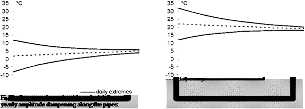
As considered throughout this article, an air-soil heat exchanger consists of an array of horizontal pipes, possibly a unique pipe, buried underneath or next to a building and situated at the inlet of the ventilation system (fig. 1). Purpose is to take advantage of the soil’s thermal inertia, so as to absorb and dampen the winter/summer or the day/night meteorological oscillation carried by the airflow, hence cutting off the cold or hot thermal peaks which would otherwise be transferred to the building. In principle this technique may be used as well for winter heating as for summer cooling purposes, although it was shown that under Mid-European climates both these modes differ as well in terms of the effect that is to be striven for (yearly versus daily amplitude dampening), as of synergy with the rest of the ventilation system and with the building itself [1].
As is schematically depicted here (fig. 1), and as will be discussed further down in all details, the main working characteristics of an air-soil heat exchanger are, in principle, as follows :
• Winter preheating and summer cooling characterize as well by daily amplitude-dampening (the day/night meteorological extremes contracting around the daily average) as by yearly amplitude-dampening (the daily average approaching the yearly meteorological average).
• While yearly heat storage propagates approximately 3 m around the pipes, daily heat storage does so on approximately 15 cm. Daily amplitude-dampening hence always surpasses yearly amplitude-dampening, which requires a wider storage volume and is limited by more in depth heat diffusion.
 |
![]()
![]()

![]() *
*
In the case of a sample soil (conductivity Xs : 1.9 W/K. m ; capacity csps : 1.9 MJ/K. m3), which will be taken as a reference, the daily heat wave hence extends on approximately 15 cm around the pipes, against 3 m for the yearly wave:
8day * 15 cm
8year * 3 m
• Thanks to the diffusive heat storage in the soil, the sinusoidal temperature input carried by the airflow:
Tin = в sm(ot) (2)
dampens exponentially along the pipe exchange surface S:
Strictly speaking, and as for all type of diffusive heat storage, this amplitude-dampening phenomenon actually goes along with delaying or phase-shifting of the input signal. It is however shown that, as long as heat storage may extend over its natural penetration depth, phase-shifting remains secondary, reason why it will here be ignored.
• The amplitude-dampening coefficient h, which will govern the dimensioning guidelines, basically results from serial linking between the convective exchange coefficient ha (air/pipe) and a diffusive exchange coefficient hs (pipe/soil):
The convective exchange coefficient ha can be computed by way of a simplified form of the Gnielinski relation [3], which relates air conductivity Xa and pipe radius r to Reynolds and Prandtl numbers Re and Pr:
The diffusive exchange coefficient hs relates to heat charge and discharge in a soil layer of thickness 8 and can be approximated by the corresponding static conduction coefficient.
Depending whether heat diffusion occurs in radial way around the pipe or in plane way downwards into the ground (as will be discussed further down), it hence writes as:
|
h * s (radial mode) r • ln(1 + 8/r) |
(6a) |
|
X h * г (plane mode) 8 |
(6b) |