Как выбрать гостиницу для кошек
14 декабря, 2021
B. M. Jones* and S. J. Harrison
Department of Mechanical and Materials Engineering, Queen’s University, K7L 3N6, Kingston, Canada
* Corresponding Author, jones@me. queensu. ca
Abstract
A thermal low-flow liquid-desiccant air handling machine was procured, installed, and field tested. The goal of the present investigation is to evaluate the field performance of the machine and characterize its operation for the temperature range of a solar thermal array. The system studied includes a natural gas boiler supplying the heat, and a cooling tower for heat rejection. System performance was evaluated for the 50 to 90°C temperature range, the operating range of solar thermal collectors. Cooling power varied between 4.3 kW and 22.8 kW for this range of temperature, with a latent heat ratio between 1.1 and 1.9, confirming that the unit is significantly dehumidifying the process air stream. Electrical COP varied between 0.58 and 4.48. Performance data indicates higher temperature solar collectors such as evacuated tube or double glazed flat plat collectors would be optimum in a solar cooling application with this system. These performance figures and methods will be used in future work to simulate and optimize a solar thermal driven dehumidification system for dedicated outdoor air systems.
Keywords: HVAC, Liquid Desiccant, Solar Thermal, Experiment
An effective approach to the problem of latent cooling demand is to decouple the latent and sensible cooling loads. This is accomplished by employing a dedicated outdoor air system (DOAS). A DOAS is designed to precondition the outside ventilation air required for the building by removing the moisture. The remaining sensible load is handled by a conventional AC system in the return air stream, avoiding overcooling and reheat. The conventional electric chiller is put in parallel with the dry outside air stream [1]. This decoupling allows each sub-system to be efficiently designed for the type of cooling load (latent or sensible). Not only does this improve energy efficiency of the overall system, but the system is now able to properly handle a wider range of cooling loads. Figure 1 shows a DOAS configuration, with RA, OA, EA, and SA referring respectively to the Return, Outside, Exhaust, and Supply Air streams.
With increasing importance placed on climate change, energy conservation, energy security, and air quality, the low flow liquid desiccant dedicated outdoor air system driven by solar thermal energy is an attractive technology. It has significant potential advantages over many alternative building energy schemes. The important advantages of the solar thermal low flow liquid desiccant concept are summarized [2-5];
• Sustainable clean solar thermal energy source
• Solar combi-system arrangements possible, increasing solar thermal array usability
• No global warming potential associated with common refrigerants
|
• Low system pressure drop • Zero carryover of corrosive desiccant material • Air cleaning and filtering • Lossless storage of solar cooling power in liquid salt solution
|
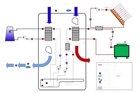
Figure 2 is a photograph of the air handling apparatus and the cooling tower. Prominent features of the system are labelled. The primary components of the dehumidification system under investigation include the heat rejection system, the air handling system, and the thermal source system. The process flows for these systems are presented in Fig. 3. The air handling system is a self contained pre-commercial prototype, and includes blowers, pumps, and data acquisition and control equipment. Figure 3 indicates the positions of sensors within the overall apparatus. Sensors are placed such that an energy balance on the sub components can be performed, and to evaluate the performance of the system. An energy balance is calculated for the system components using flow meters and inlet/outlet temperature probes. Table 1 lists the system operational variables provided by the manufacturer and those used in experiment [6].
|
||||||||||||||||||||||||||||||
|
|
O* Blower |
|
|
|
|
|
|
|
|
|
|
|
|
 |
|
|
|
|
|
|


Figure 3 — Process flows and instrumentation
The system was operated over 20 days in July in Kingston, Ontario, Canada. The range of water temperatures expected for a solar thermal application was the primary independent variable. Table 2 is a summary listing of the daily operation of the air handling system under 4 types of regenerator heating profile. The 10th, 13th, and 20th correspond to the 50, 70, and 90°C heating set point. Average conditions for daily operation are listed.
|
Table 2 — Experimental results Day (July 2008)
|
System operation plots for the 25th of July are presented in Figs. 4 and 5. The 25th was operated on a time varying simulated solar heating profile, simulating a 70m2 evacuated tube collector array. Figure 4 is a plot of the conditioner performance for the 25th of July. The system begins operation when the temperature of the solar thermal array reaches 50°C, at 9:30 in the morning. The temperature profile can be seen in the top section of Fig. 4. The temperature profile approaches 80°C as the day progresses and the incident radiation on the simulated vacuum tube collector increases. The temperature profile is adjusted by the programmable logic controller every 30 minutes. From 2, the average cooling rate is 13.5 kW with a latent heat ratio of 1.4. The middle section of Fig. 4 displays the temperature at the process air inlet and outlet. The temperature rises an average of 2.4°C for this day. The bottom section of Fig. 4 shows a significant dehumidification effect, a change in absolute humidity averaging 3.6 g/kg. This amounts to a total absorption of 208.9 kg of water for this day. From the middle section of Fig. 5, it is observed that the absorption and desorption rates are similar. This indicates that the machine is approaching steady state operation even over a varying temperature profile The total amount of water desorbed for this day is 214.1 kg. The bottom section plots the coefficients of performance for this day. The average thermal COP for the 25th is 0.68, the average cooling COP is 0.48, and the average electrical COP is 2.68 for this solar temperature profile.
|
Figure 4 — Conditioner performance under simulated solar load |
|
Figure 5 — Regenerator solar heating profile and system COP’s |
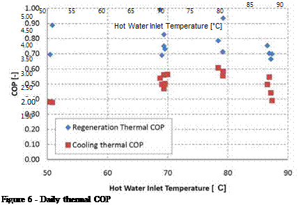
Figures 6 and 7 display the average daily coefficients of performance for the data set. The thermal regeneration COP is the energy of desorbed water divided by the heat absorbed. The cooling COP is the energy change of the air stream divided by the heat absorbed. The electrical COP is defined as the energy change of the air stream divided by the electricity consumption rate, which was 5.5 kW for this system.
Overall, the regenerator COP averaged 0.81 for the days of constant heating temperature operation, while the cooling COP is an average of 0.53. The cooling COP is lower due to the enthalpy gained by the desiccant as it condenses and absorbs water vapor from the process air. The cooling COP can be improved with a higher capacity heat rejection system. The electrical COP can be improved with variable speed drives on pumps and blowers.
 |
Figure 7 — Daily electrical COP
A liquid desiccant air handling system driven by thermal energy was procured. Piping, valves, motors, and thermal sub-components were connected. Transducers included flow meters, thermistors, and relative humidity sensors. Desiccant solution concentration was monitored using a batch process density meter and a density-concentration correlation. A data acquisition system was designed and installed. The system is controlled using a programmable logic controller using relay ladder logic controlling the drive units for pumps and fans, and monitoring system faults. The system commissioning included troubleshooting and government safety inspections.
The system was tested in a field environment. The data set was processed giving enthalpy flows and performance figures for daily operation of the machine. An enthalpy balance on the system was used to check sensors and assumption of adiabatic operation. The assumption of an
adiabatic control volume around the conditioner and regenerator was found to be valid. Regenerator thermal COP was calculated to be 0.76 to 0.99, and conditioner thermal COP was in the range of 0.38 to 0.61 for the entire data set over 50°C to 90°C. Electrical COP increased from 0.58 at 50°C to 4.48 at 90°C. The average latent heat ratio was 1.1, 1.3, and 1.5 respectively for the three temperatures evaluated, showing that the heat load on the conditioner increases as the desiccant is heated in the regenerator. The average cooling power was 4.3, 14.1, and 21.3 kW for the temperature range. Data indicates that high temperature solar thermal collectors would achieve better performance based on their ability to maintain a desired cooling power and their increased electrical COP.
Future work in this project will include coupling a solar thermal array incorporating liquid desiccant storage, and upgrading drive units to improve the system electrical COP.
[1] Mumma, S. A. (2007). DOAS and desiccants Engineered Systems, 24, 37 — 49.
[2] Mei, L. & Dai, Y. (2008) A technical review on use of liquid-desiccant dehumidification for airconditioning application Renewable and Sustainable Energy Reviews, 12, 662 — 89
[3] Hwang, Y.; Radermacher, R.; Al Alili, A. & Kubo, I. (2008) Review of solar cooling technologies HVAC and R Research, 14, 507 — 528
[4] Katejanekarn, T. & Kumar, S. (2008) Performance of a solar-regenerated liquid desiccant ventilation preconditioning system Energy and Buildings, 40, 1252 — 1267
[5] Jain, S. & Bansal, P. (2007) Performance analysis of liquid desiccant dehumidification systems International Journal of Refrigeration, 30, 861 — 72
[6] Lowenstein, A.; Slayzak, S. & Kozubal, E. A zero carryover liquid-desiccant air conditioner for solar applications International Solar Energy Conference, 397 — 407