Как выбрать гостиницу для кошек
14 декабря, 2021
Сегодня каждый, кто собирается в отпуск и не знает, с кем оставить своего котика или кошку, может во[...]
Panagiotis Tsekouras[23], Mario Motta[24], Aristotelis Aidonis1, Dimitris Chasapis1,
Christina Hatzilau[25], Constantinos Balaras4
1Center for Renewable Energy Sources (CRES)
19th km Marathonos Ave., GR-190 09 Pikermi, Greece
Email: ptsek@cres. gr. aidonis@cres. gr. chasapis@cres. gr
2 Politecnico di Milano. Dipartimento di Energia — Piazza Leonardo da Vinci. 32 — 20133 Milano — Italia
Email: mario. motta@polimi. it
3 National Technical University of Athens (NTUA). Heroon Polytechniou 9. GR 15780 Zografou
Athens. Email: hatzilau@central. ntua. gr
4 National Observatory of Athens (NOA). Institute for environmental Research & Sustainable
Development. Group Energy Conservation. I. Metaxa & Vas. Pavlou. GR 15236 P. Penteli. Greece
Email: costas@meteo. noa. gr
The market of the solar combi-systems (providing heat for both domestic hot water — DHW — and space heating) is continuously growing. especially in central and northern Europe. In Europe in 2006 the market share of combi-systems had been about 5% [Weiss et al. 2008]. In Austria. solar combi — systems had a market share of almost 40% until 2007 [ESTIF. 2007] while in Germany. the market share of combi-systems has reached 45% in 2007 [Koldehoff. 2008]. Moreover. the use of solar assisted air conditioning (SAC) is reaching the market level. with significant growth in European commercial and residential buildings [Balaras et al. 2007]. Recently. various small scale SAC systems appeared on the market [SOLAIR. 2008]. The combination of solar heating and cooling seems very promising and can increase the total solar fraction1.
The main “drawback” of solar combi systems has been the fact that excess summer solar heat couldn’t be utilized. thus making the system economically less attractive. and creating some technical problems related to stagnation (the condition when there is available solar radiation but no load and the liquid in the primary loop usually vaporizes). Since high building cooling loads generally coincide with high solar radiation. the excess solar heat can be exploited by a combi+ system (“combi+” or “combi plus” is the term used to identify the combination of solar heating and cooling systems).
Nevertheless. even in a common solar combi+ system. there is still some mismatch between the availability of solar energy and the loads. especially during the intermediate “low load” seasons in spring and autumn (low or even no heating and cooling space loads. only domestic hot water load). Moreover. the consecutive days in winter with low solar radiation. actually create a limit for the system’s solar fraction for space heating and DHW. Therefore. even a solar combi+ system can
hardly reach particularly high solar fractions (e. g. over 80% in terms of total solar fraction and over 70% in terms of partial space heating fraction).
A “solution” for the utilization of the excess solar heat during the “low load” periods is the use of a seasonal storage tank (SST), filled with water. There are several SST systems in operation [Schmidt, 2004]; most of them are quite large (thousands of m3 of water equivalent storage), typically ranging between 1.5 and 4 m3 per unit surface of solar collectors.
This paper focuses on an investigation of how to achieve particularly high solar fractions (over 90%) for heating and cooling of buildings through an optimized SST. The size of the SST is small compared to common practice and has some innovative aspects that are described in the following sections.
The work reported here-in is part of the ongoing European project “HIGH-COMBI” (Contract No: TREN/07/FP6EN/S07.68923/038659) which aims at developing high solar fraction systems by an innovative combination of optimized solar heating, cooling and storage technologies (www. highcombi. eu). In the frame of the project, five demonstration plants will be constructed in Greece, Italy, Austria and Spain using different technologies, components and control strategies in order to achieve high solar fractions’ values. Demonstration plants’ monitoring data will be analyzed, the simulation and design tools will be validated and the plants’ performance will be evaluated. A market analysis will be carried out in order to estimate the potential penetration for these systems in the European heating and cooling market. The sectors of the implementation are all medium and large buildings end-users having heating and cooling loads throughout the year.
M. Bakker1*, W. G.J. van Helden1, and A. Hauer2
1 ECN, Energy Research Centre of the Netherlands, P. O. Box 1, 1755 ZG Petten, The Netherlands
2 ZAE Bayern, Walther-Meissner-Strasse 6, D-85748 Garching, Germany
Corresponding Author, m. bakker@ecn. nl
Abstract
A new IEA SHC/ECES Joint Task will be started on January 1, 2009. The objective of this new task, designated SHC Task 42 and ECES Annex 24, is to develop advanced materials for compact thermal energy storage, which can be used for renewable heating and cooling as well as for energy conservation. The task focuses on thermochemical materials, including sorption and composite materials, as well as on phase change materials, and includes work on material engineering and development, characterisation, numerical modelling, demonstration, and dissemination.
Keywords: thermal storage materials, renewable heating and cooling.
Thermal energy storage is an important technology for renewable energy systems. By improving the effectiveness of thermal storage, the effectiveness of all renewable energy technologies that supply heat can be improved.
Particularly for solar thermal systems, thermal energy storage is essential. To reach high solar fractions, it is necessary to store heat (or cold) efficiently for longer periods of time. Until now, no cost-effective compact storage technologies are available to do this. For high solar fraction systems, hot water stores are expensive and require very large volumes of space. Alternative storage technologies, such as phase change materials (PCMs) and thermochemical materials (TCMs) are available on a laboratory scale. However, more research and development is needed before these technologies can be developed into commercial solutions.
In several IEA annexes, both ongoing and completed, it was concluded that materials are the main bottleneck for finding effective solutions for compact thermal energy storage, and that there is a need for new storage materials with a higher specific energy storage density and lower material cost.
Around the world, several groups are working on either thermal energy storage materials or applications. However, these activities are not sufficiently linked. The current activities are either limited to specific applications, or to specific materials. What is needed, and what can be provided by this new task, is a way to bring the ongoing work on materials and applications together.
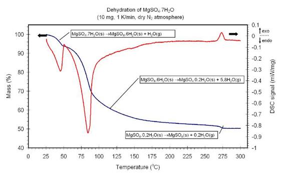
In the literature, several intermediates have been identified during the dehydration of MgSO4.7H2O. However, the published results are at some points conflicting on which intermediates are formed [2-6]. The dominant natural occurring magnesium sulfates on earth are Epsomite (MgSO4.7H2O), Hexahydrate (MgSO4.6H2O) and Kieserite (MgSO4.H2O). Since it is not clear which other intermediates are formed, it was decided to measure the dehydration of MgSO4.7H2O anew. The dehydration of MgSO4.7H2O was studied by means of thermogravimetric analysis (TGA) and differential scanning calorimetry (DSC). TGA involves the measurement of the mass change as function of time and DSC involves the measurement of heat as function of time, in which both are subjected to a predefined temperature program. The experimental results indicated that dehydration of MgSO4.7H2O proceeds in three discrete steps as illustrated in Figure 1:
|
Fig. 1. A typical TGA-DSC curve for dehydration of MgSO4.7H2O. The blue line denotes TGA curve and the red line denotes the DSC curve. |
The above Figure shows that the first dehydration reaction occurs at low temperature (<50°C) and involves the loss of one water molecule. The largest number of water molecules is dehydrated during the second reaction, which also allows storing the largest amount of energy of the three dehydration reactions: almost 10 times more energy compared to water (~2.3 GJ/m3 compared to 0.25 GJ/m3 for water in the temperature range 25-85°C). Additionally, the reaction occurs between approximately 60°C and 200°C: a temperature range which can be almost completely covered using a vacuum tube solar collector (Tmax=150°C). For these two reasons the second dehydration reaction is most interesting
for seasonal solar heat storage. Figure 1 also shows that the last water molecules are dehydrated at a high temperature (~275°C). In contrast to the first two dehydration reactions, the third dehydration reaction involves an exothermic process (indicated by the positive DSC signal). Ruiz et al [3] suggests that the final transition to MgSO4 includes an exothermic reaction due to recrystallization of an amorphous precursor. This suggestion was further investigated by performing X-ray diffraction (XRD) experiments as shown in Figure 2:
When the temperature of the sample is increased from 25°C to 55°C, the XRD measurement shows that MgSO4.7H2O is converted to MgSO4.6H2O. This result is in agreement with the results obtained by the TGA-DSC experiments (see also Figure 1). No peaks are observed in Figure 2 between 80°C and 276°C, indicating that an amorphous state is formed when MgSO4.6H2O is dehydrated further. This observation is in agreement with the findings of Ruiz et al [3].
The XRD measurements shows that the material only recrystallizes at T>276°C. It should be noted that recrystallization only occurs when a small amount of water is present (0.2 water molecules per MgSO4 molecule, see Figure 1) after which an exothermic reaction is observed. This could be explained by the hypothesis that below the critical water content of 0.2 water molecules per MgSO4 molecule, a spontaneous exothermic crystallization occurs that expels the last water that is present in the material. The XRD measurements confirm the observations from TGA-DSC experiments that the material is completely dehydrated at 300°C.
L. H. Godinho1*, M. P.F. Gra^a 1,2
1) Prirev, Lda, Zona Industrial de Vagos, Lt.61, 3840-385 Vagos — Portugal
2) Physics Department, I3N — Institute of Nanostructures, Nanomodelling and Nanofabrication,
Aveiro University, Campus Universitario de Santiago, 3810-193 Aveiro, Portugal
* Corresponding Author, lhalgodinho@gmail. com
The main purpose of a greenhouse is to create and maintain a controlled artificial environment that will favour the crop production with the maximum profit. Late increase on fuel prices, together with colder than normal seasons, make heating costs a significant burden on greenhouse operations. Therefore, the use of renewed energy systems, namely solar thermal systems, to control the inner environment of agricultural greenhouses becomes an economical and technological topic of unquestionable interest. This publication is related with the analytical analysis of the possibility of using a solar thermal system to control the climate environment of a greenhouse. Preliminary calculations show that, in certain climate conditions, a solar greenhouse can collect sufficient solar energy to feed, at least, another standard thermally optimised greenhouse of the same size. The implementation of this project, which is based on Portuguese Utility Model n°10218 — “Thermal Solar System for Collection, Storage and Distribution of Heat at Low Temperature”, considers the construction of a prototype and, later, of a larger industrial greenhouse, to verify the technological and economical viability of the patented idea.
Keywords: greenhouse, energy, solar, agriculture,
Since the beginning of the XX century the world has been suffering from rising exploitation of its natural resources, with the resulting consequences in pollution and degradation. Oil, for example, considered a traditional energy source, have been extracted in such huge amounts that oil-wells already started to be depleted less than 100 years after the beginning of its effective use.
The “Lisbon strategy”, set in March 2000 by the European leaders, assumed the commitment of the UE to become, up to 2010, an economy based on the most dynamic and competitive knowledge of the world, capable to guarantee a sustainable economic growth, with more and better jobs, bigger social cohesion and respect for the environment. One of the main goals will be the ambient sustainability, that is, to develop and to spread out the echo-innovations and to build the leadership in the echo-industry; to adopt policies to generate long term improvements supported in increased productivity through echo-efficiency. Economic growth will be supported by the echo-innovations leading to a decrease in pollution and to a more efficient management of the resources. Many examples of these echo-efficient innovations already exist in several areas, agriculture and energy included.
The conversion of traditional agriculture, which is strongly climate dependent and characterized by extremely hard work conditions, in a more technical agriculture in controlled environment, will have an enormous impact in the reduction of the risk and in the increase of productivity and quality of the cultures, providing more appealing work conditions.
Basically, greenhouses are solar collectors with poor heat storage capacity. From local weather conditions in the last years we know that in late autumn, winter and beginning of spring, night temperatures can be quite low for long periods. Temperature represents a critical factor to the survival and growth of the plants. In fact, keeping the greenhouse at the most suitable temperature for the development of a given plant will significantly improve its productivity and quality.
Also in summer we can have in greenhouses a phenomena called “inversion” whenever the inside temperature drops dramatically at dawn when the sun rises, due to the evaporation of water condensed during the night.
Traditional Portuguese greenhouse consists of a galvanized iron pipe structure, covered with single layer of polyethylene (PE) film. This type of greenhouse implies enormous heat losses with consequent high fuel consumption. As a result, an increasing number of farmers have just switched off the heating and given up some greenhouse cultures in the last years due to the rise in energy costs.
The main objectives of this project are the thermal efficiency analysis of the greenhouse (type of covering, heating system, thermal curtains, etc.) and how much of its heating by traditional energy sources can be replaced by solar energy. The economic viability of its construction, the use of low cost (and yet efficient) polymeric solar thermal collectors together with simple water heat storage tanks — made from expanded polystyrene (EPS) blocks with an inner bag of reinforced polyvinyl chloride (PVC) film — and the way to transport and release the thermal energy inside the greenhouse, will also be studied.
During the cold night periods, water from the storage tanks will flow through small polymeric tubes inside the greenhouse and will heat the ground (if buried), or the bottom of the vases (if covering the growing tables).
At the energy level, the phases of this project are:
• pre-study of thermal properties in the design phase of the project;
• design of energy monitoring systems;
• data analysis and presentation of results.
Intended results are:
• substantially improved production conditions (quantity and quality);
• increased effectiveness of the heating using thermal efficient greenhouses;
• lower fuel consumption and, consequently, less air pollution;
• promotion of specialized agriculture, more competitive and with better work conditions.
In this paper we describe the analytical analysis that supports this solar thermal system project.
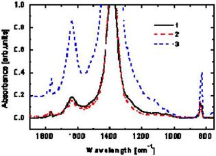
Two peaks appeared on DSC solidification curve of a Composite 3 (Fig.1), as a simple signal of inhomogeneous composite or chemical products generated during crystallization process. The recrystallization of the Composite 3 was made with DSC at a cooling/heating rate of 0.50C/min and temperature range from 150-2200C. Comparable FTIR spectral study was performed on Composite 3 for examination of the possible chemical degradation or chemical interaction (Fig.2).
|
Fig.2. FTIR spectra of the (Na/K)NO3eutectics/graphite GFG (curve 1), compared to the (Na/K)NO3eutectics/graphite composite NG (curve 2), and to the (Na /K)NO3 Eutectics (curve 3). |
Relative intensities of the absorption peaks were almost the same for the two samples of salt/eutectics graphite composites Fig.2, (1), (2), but lower as compared to the single NaNO3/KNO3 eutectics (3). Evaluations of the spectra provided with an evidence of a maximum characteristic absorption band at 1379 cm-1, displayed for vibrations of the nitro functional group of NaNO3 and KNO3 compounds. Products of chemical degradation or chemical reaction were not identified from anion frequencies recorded for all samples.
The main findings from the simulation are as follows:
The heat exchanger effectiveness increases with
• Smaller sand grain size
• Air inflow velocity
• Heat exchanger dimensions (height and width)
With the air and sand inflow temperatures of 800 °C and 200 °C, the obtainable average sand and air output temperatures are in the range TSand= 720-740 °C, TAir= 250-270 °C and heat exchanger effectiveness in the range sHX = 85-90 %.
Further results are
• For sand grain sizes < 3 mm and heat exchanger dimension of 50 cm height and 5 cm width (as given in the heat exchanger set-up described below) a smaller grain size has limited effect on the heat transfer
•  Dynamic behaviour: short-term sand blockage with blocking period below 20 s are uncritical with respect of air outflow temperatures increase due to the sand bed heat capacity
• To minimize pressure drop and to increase specific heat flux per volume (dimension of 1 MW/m3) a sand grain size dSand =1-3 mm is favourable
In the methods listed above, effectiveness is principally equated in terms of the total exergy content of an experimental TES, with comparison to an ideal and/or mixed system. Although this is useful when assessing the overall performance of a complete simulation, the indices are not particularly suited to highlight not only the effect of thermal mixing within a TES, but more importantly, clearly indicate at which point turbulent mixing effects become negligible, if at all. They also offer a varying degree of applicability for different TES simulations. Panthalookaran’s method, for instance, does not seem to apply easily to variable temperature inflow conditions. [7]
|
stored |
|
(t) |
|
V£CR (t) _ |
|
if Ver (t) > 0 |
|
(4) |
|
(5) |
|
£ stored |
|
(t 2) -£ |
|
stored |
|
(ti) |
|
12 ti |
|
stored, real |
|
stored, strat |
|
(t) (t) |
|
■ 100% |
In support of the existing indices, a new characterization index has been derived and is proposed in eq. (4). The index, deemed the Exergy Charge Response (nCR), examines the rate at which the exergy stored within a real TES increases, and compares it to that of an ideal tank. The index is derived principally from eq. (3) above, which describes the exergy stored within a TES at a given time.
The applicability of the Exergy Charge Response is limited by the understanding that, given sufficient energy input with high inlet temperatures, a fully-stratified and a fully-mixed tank will eventually reach similar exergy levels:
да да со
J£stored, strat(t) £stored, real (t) stored, mix (t) if! iS Estored (t) > 0 (6)
0 0 0
It is therefore possible that at some point towards the end of a simulation with high energy availability, n^CR must become greater than 100%. This will only occur, however, when the energy response efficiency of the tank, tfER, begins to decrease from 100%. Therefore, so long as (nER > 0), hcR will be affected primarily by internal mixing, particularly at the early stages of charging.
The particular advantage of the Exergy Charge Response applied to TES simulations is the ability to effectively monitor the transient relationship between the thermocline and the fluid motion within the TES itself. It is clear that when п^ск ~ 1, the inlet plume is not thermally mixing the TES, and oppositely so when ncR ~ 1.
Measurements have shown a maximum storage capacity of approximately 30 kWh for operation with external melting. Otherwise, a maximum storage capacity of 45 kWh is possible. In this case no liquid phase is left in the ice store. At a charging temperature of -10°C, the ice storage can be loaded with System A at a rate of 4 kW, on average (Figure 4). System B provides an average charging rate of 2.5 kW. Fluctuations at the beginning of the charging are caused by adjustment of the thermostat. Figure 5 compares the charging times of both systems at -12 and -10°C.
|
900 |
|
840 |
|
780 |
|
720 |
|
660 |
|
600 |
|
540 |
|
480 |
|
420 |
|
360 |
|
-12 -10 Charging Temperature / [°C] |
|
Figure 5: Charging System A at different flow temperatures |
 |
|
Figure 5 compares the charging times of System A and B at two different charging temperatures.
As expected from the different charging rate System A charges the ice store faster than System B. Charging the ice store at -10°C with System A takes 421 minutes and with System B 657 minutes. Table 1 offers an overview about all results for charging.
|
Table 1: Experimental results for charging
|
The ANZEH is a two storey, wood-frame, detached building, with 210 m2 of inhabitable area. The insulation values selected for the building envelope are higher than conventional Canadian homes: walls with 5.6 RSI (U = 0.18 W/m2K), ceiling with 12 RSI (U = 0.08 W/m2K) and floor insulation of 4.6 RSI (U = 0.22 W/m2K). This house relies heavily on passive solar design to satisfy its
[7] The hygroscopy increases in the order: dry, slightly hygroscope, hygroscope, strongly hygroscope.
[8] O = Oxidizing agent, Xn = Harmful, N = Dangerous for the environment, T = Toxic
[9] No data available, dry to hygroscope
[10] Introduction
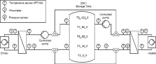
Now this testing facility has been extended by variable flow pumps and a 500 l storage tank without any built-in components such as stratification device or heat exchanger as shown in Figure 1.
|
1st International Congress on Heating, Cooling, and Buildings — 7th to 10th October, Lisbon — Portugal /
Fig. 1: System scheme of the testing facility |
All temperatures and volume flow rates are measured in all four circuits so all energy fluxes can be evaluated. Additionally the pressure difference at the slurry side of the hot side heat exchanger is recorded so it can be compared to water. The temperatures in different heights of the storage are also measured, so the charge state and the degree of stratification can be ascertained. The sensors are labelled TS_xx_yy with xx representing the height from the bottom and yy the distance from the centre of the storage in centimetres.
The sensors and measuring equipment have the following accuracies:
— All temperature sensors are Pt100 class A with dT = ± (0,15 °C + 0,2% • T) or better (if manually calibrated)
— The pressure sensors have a dp = -0,1% due to pressure at 2bar and a thermal dp of — 0,25% at 0 °C and 1% at 75 °C
— The volume flow rate is measured by a magnetic flow meters with dV = ± (1 mm/s + 0,3% • V)
— The measuring equipment has deviations of ± 0,06 °C for Temperatures, ± 1mbar for pressures and ± (0.0003 • V + 0,5 l/h) for volume flow rates
For the measurement of thermal powers the maximum inaccuracy adds up to ±3,1% at 2000l/h.
The properties of the components are as follows:
— Nominal chiller capacity 0.5.. .20 kW
— Heater power 0.5.20 kW
— Volume flow rate of pumps 50.2000 l/h
The testing facility is designed for operation between -10 °C and 80 °C. This wide range of temperatures and the good variability of the components offer the possibility to reproduce a large variety of system configurations and operating conditions. The control program can automatically perform different series of measurements as to be seen in the subsequent example. Furthermore the program can read load data files and adjust the heating and cooling power accordingly. Thus the effect
of PCS can be evaluated under reality-like conditions. This function can also be used to verify control strategies developed in simulations.