Как выбрать гостиницу для кошек
14 декабря, 2021
Сегодня каждый, кто собирается в отпуск и не знает, с кем оставить своего котика или кошку, может во[...]
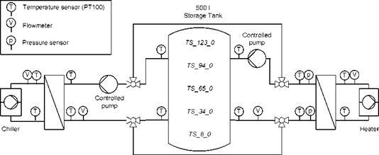
Now this testing facility has been extended by variable flow pumps and a 500 l storage tank without any built-in components such as stratification device or heat exchanger as shown in Figure 1.
|
1st International Congress on Heating, Cooling, and Buildings — 7th to 10th October, Lisbon — Portugal /
Fig. 1: System scheme of the testing facility |
All temperatures and volume flow rates are measured in all four circuits so all energy fluxes can be evaluated. Additionally the pressure difference at the slurry side of the hot side heat exchanger is recorded so it can be compared to water. The temperatures in different heights of the storage are also measured, so the charge state and the degree of stratification can be ascertained. The sensors are labelled TS_xx_yy with xx representing the height from the bottom and yy the distance from the centre of the storage in centimetres.
The sensors and measuring equipment have the following accuracies:
— All temperature sensors are Pt100 class A with dT = ± (0,15 °C + 0,2% • T) or better (if manually calibrated)
— The pressure sensors have a dp = -0,1% due to pressure at 2bar and a thermal dp of — 0,25% at 0 °C and 1% at 75 °C
— The volume flow rate is measured by a magnetic flow meters with dV = ± (1 mm/s + 0,3% • V)
— The measuring equipment has deviations of ± 0,06 °C for Temperatures, ± 1mbar for pressures and ± (0.0003 • V + 0,5 l/h) for volume flow rates
For the measurement of thermal powers the maximum inaccuracy adds up to ±3,1% at 2000l/h.
The properties of the components are as follows:
— Nominal chiller capacity 0.5.. .20 kW
— Heater power 0.5.20 kW
— Volume flow rate of pumps 50.2000 l/h
The testing facility is designed for operation between -10 °C and 80 °C. This wide range of temperatures and the good variability of the components offer the possibility to reproduce a large variety of system configurations and operating conditions. The control program can automatically perform different series of measurements as to be seen in the subsequent example. Furthermore the program can read load data files and adjust the heating and cooling power accordingly. Thus the effect
of PCS can be evaluated under reality-like conditions. This function can also be used to verify control strategies developed in simulations.