
Как выбрать гостиницу для кошек
14 декабря, 2021
Сегодня каждый, кто собирается в отпуск и не знает, с кем оставить своего котика или кошку, может во[...]
Fig. 4 and 6 present effectiveness curves in which the capacity of the TSU is constant. These figures can be readily used as design curves which characterise the performance of the TSU subject to a single parameter, phase change fraction. In any design, using Eqn. (2), the minimum effectiveness can be determined which will define the outlet temperature from the TSU which will remain within specifications. For a given set of parameters this effectiveness is now directly related to the capacity of the TSU.
Consequently the proportion of phase change can be found which will ensure that the outlet temperature during the charging/discharging process will meet design requirements. This proportion defines the redundant PCM which occurs due to the 2nd law losses described in [3]. Consequently, the size of the TSU can be determined for a given set of parameters which will reliably meet thermal performance criteria. For example, in the solar heating application the minimum outlet temperature during the freezing process is 30 oC. This equates to a minimum effectiveness of 0.43. If the TSU is defined by H=50 mm and a flow rate of 0.35 kg/s, then, referring to Fig. 6, the useful proportion of the TSU is 67%. Therefore, to achieve the required, capacity the TSU should have 50% more PCM.
Using the knowledge of the solid/liquid phase change profile, it is possible to develop a one dimensional equation of the effectiveness of a TSU for design purposes, applying the s-NTU approach. The effectiveness was defined in terms of the phase change fraction and is able to reflect two dimensional and one dimensional phase change within a PCM slab. The use of the phase change fraction enables the characterisation of the TSU into a single effectiveness chart. From a design perspective this presents a useful method for determining the size of the TSU, which is the principle unknown variable in the design of the thermal storage unit. This analysis process also provides a method for optimisation of a design by enabling direct comparison of the impact of different parameters.
[1] E. Halawa, F. Bruno and W. Saman, Energy Conversion and Management, 46 (2005) 2592-2604.
[2] D. Morrison and S. Abdel — Khalik, Solar Energy, 20 (1978) 57-67.
[3] H. El-Dessouky and F. Al-Juwayhel, Energy Conversion and Management, 38 (1997) 601-617.
[4] K. Ismail and M. Goncalves, Energy Conversion and Management, 40 (1999) 115-138.
[5] E. Halawa (2006) Thermal Performance Analysis of a Roof Integrated Solar Heating System Incorporating Phase Change Thermal Storage, PhD Thesis, University of South Australia.
[6] A. Sari and K. Kaygusuz, Energy Conversion and Management, 43 (2002) 863-876.
[7] J. P. Holman (1992) Heat Transfer, 7th edn, Mc Graw Hill, London.
|
A, m2 |
Heat transfer area |
Re |
Reynolds Number |
|
Cp, kJ/kgK |
Specific heat of fluid |
RT, K/W |
Total thermal resistance |
|
h, W/m2K |
Convection heat transfer coefficient T1, oC |
Inlet fluid temperature |
|
|
H, m |
Half slab thickness |
H о о |
Outlet fluid temperature |
|
k, W/mK |
Thermal conductivity |
T, oC |
PCM melting point |
|
L, m |
Length of slab |
U, W/m2K |
Overall heat transfer coefficient |
|
m, kg/s |
Fluid mass flow rate |
W, m |
PCM slab width |
|
NTU |
Number of transfer units |
x, m |
Direction in flow path |
|
Nu |
Nusselt Number |
y, m |
Direction perpendicular to flow path |
|
Pr |
Prandtl Number |
s |
Heat exchange effectiveness |
|
5 |
Phase change fraction |
V. M. van Essen1*, H. A. Zondag1, R. Schuitema1, W. G.J. van Helden1 and C. C.M. Rindt2
1Energy research Centre of the Netherlands ECN, P. O. Box 1, 1755 ZG Petten, The Netherlands
2Department of Mechanical Engineering, Eindhoven University of Technology (TU/e), 5600 MB Eindhoven,
The Netherlands
* Corresponding Author, v. vanessen@ecn. nl
Abstract
Magnesium sulfate hepta hydrate (MgSO4.7H2O) was studied as possible thermochemical material for seasonal storage of solar heat. Both hydration and dehydration were investigated and it was found that the material was able to take up and release almost 10 times more energy than water of the same volume. The amount of water taken up and energy released by the material turned out to be strongly dependent on the water vapor pressure and temperature. Unfortunately, the material was not able to release all the stored heat under practical conditions. Despite this problem, valuable information on the dehydration and hydration behavior of MgSO4.7H2O was acquired and the characterization procedure will also be used for future characterization of other salt hydrates for thermochemical materials.
Keywords: compact thermochemical seasonal heat storage, characterization, magnesium sulfate, salt hydrate
Households in the Netherlands use about 15% of the total energy consumption for space heating and domestic hot water. The energy consumption in the built environment can be reduced by energy saving measures (improved insulation, heat recovery, etc.). A substantial part of the remaining energy demand can be fulfilled by using renewable energy sources such as solar energy.
The heat demand in summer can be completely fulfilled using solar heat, but in winter the heat demand exceeds the solar supply. To accommodate this difference in time between the solar energy surplus in summer and the energy demand in winter, a seasonal thermal storage is needed.
Traditionally water is used for storing solar heat (e. g. solar boiler) for short time periods, however, long-term heat storage will require a large water tank (>50 m3) that is often too large to be placed inside a building. As an alternative, it is possible to store energy by means of chemical processes, making use of the reversible reactions: C + heat «• A + B
During summer, the thermochemical material (TCM) dissociates under influence of solar heat into components A and B, which are stored separately. In the discharging mode, the two components (A and B) react to form the original TCM while releasing the stored solar heat. No reactions occur as long as the two components are stored separately, which means that thermo chemical storage can be used for loss-free storage and transportation of heat.
Interesting TCMs are cheap, non-toxic, non-corrosive, have sufficient energy storage density, and have reaction temperatures in the proper range. These requirements are fulfilled by a number of salt hydrates. A previous theoretical study [1] identified magnesium sulfate hepta hydrate (MgSO4.7H2O) as a promising material for long-term heat storage, by means of the following reaction:
MgSO4.7H2O(s) + heat «• MgSO^s) + 7H2O (g)
In this work, measurements on magnesium sulfate are presented that give information on the suitability of magnesium sulfate as thermochemical material for seasonal heat storage. Additionally, information is given on parameters important for the design of thermochemical seasonal heat storage using magnesium sulfate.
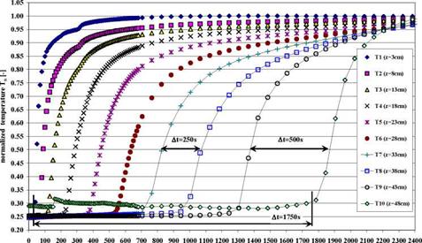
In Fig. 4 the normalized temperature Tn=T(t)/Tmax development in function of time t in a fixed bed of spherical zeolite 13X particles of average diameter dp=1.51mm is shown. The direct correlation of T and p in the fixed bed sorption process was shown in Fig. 3. An increased time delay At can be seen in which two succeeding temperature sensors in the equally spaced array of distance l=5cm are measuring the same temperature values. For example the time delay At=[t(T8)-t(T7)]=250s or At=[t(T10)-t(T9)]=500s can be measured for the normalized temperature of Tn=0.5 at the sensor T7 (z=33cm) and T8 (z=38cm) or T9 (z=43cm) and T10 (z=48 cm). These time delays are strongly dependent on the average particle diameter dp and the vapour pressure p(T) at the entrance to the sorption material fixed bed. For comparison in Fig. 5 the data for a pressure of p=29.7mbar i. e. the temperature T=25°C in the sorbate water tank, at the entrance to the same fixed bed are shown and a reduction of the time delay for Tn=0.5 to At=[t(T8)-t(T7)]=60s and At=[t(T10)-t(T9)]=100s can be seen.
|
time t [s] Fig. 4: Normalized Temperature Tn in function of time t and position z in a fixed bed of spherical zeolite 13X particles of average diameter dSp=1.51mm. The water vapour pressure at the entrance to the fixed bed was p=16.3mbar at the start of the measurement. The delay time At(z) of two succeeding temperature sensors measuring the same temperature depends of the position z in the fixed bed. |
SHAPE * MERGEFORMAT

|
Fig. 5: Normalized Temperature Tn in function of time t and position z in a fixed bed of spherical zeolite 13X particles of average diameter dSp=1.51mm. The water vapour pressure at the entrance to the fixed bed was p=29.7mbar at the start of the measurement. The delay time At(z) of two succeeding temperature sensors measuring the same temperature depends of the position z in the fixed bed. |
 |
In Fig. 6 the time dependent development of the water temperature in the evaporator heat exchanger inlet T(HX in) and outlet T(HX out) are shown for a zeolite 13X fixed bed of dp=1.51mm a) and dp=2.63mm b) and a water inlet temperature of T(HX in)=25°C. After a time of t=200s to t=250s the minimum T(HX out) is reached and the temperature difference AT= T(HX in)-T(HX out)=3.5°C and AT=5.0°C are reached for the two particle size distributions. A linear temperature increase T(HX out) in the sorbate water tank is observed for adsorption process times longer than about t=300s.
|
0 |
0 50 100 150 200 250 300 350 400 450 500 550 600 time t [s] |
|
300 |
![Подпись: тппптплпппппп □ □ о □ с О temperature T(HX out) temperature T(HX in) о AT= 5.0 °C «о**30 о o< «*** 0 50 100 150 200 250 300 350 400 450 500 550 600 time t [s]](/img/1128/image600.gif) |
|
In Fig. 7 the pressure p measurement in function of the position z and the time t is shown for the pressure sensors installed at the first z=28cm of the fixed bed. A linear dependence of the water vapour pressure p from the position z can be assigned. While the process time t is increasing the pressure gradient dp/dz in the fixed bed is decreasing. This effect is illustrated with the two lines a) and b). Two effects are contributing to this behaviour. The adsorption which in this zeolite 13X is governed through the Langmuir isotherm [13] is dominating as long the equilibrium concentration c(p, T) is not reached.
a) b)
Fig.6: water temperature T as a function of time t at the outlet T(HX out) and the inlet T(HX in) of the evaporator heat exchanger at the start temperature T(HX in)=25°C for a fixed bed with dp=1.51mm a) and a fixed bed with dp=2.63mm b). After a time of approximately t=200s the minimum of the outlet temperature T(HX out) in is reached and from there on a linear increase of the temperature T(HX out) can be observed.
Fig. 7: Pressure p development in function of the
position z in the fixed bed of spherical zeolite 13X
particles of average diameter dSp=1.51mm and water
vapour pressure p(T)=16.3mbar at the entrance to the
fixed bed. The curves with the parameter time t are
showing a linear dependence of the pressure p(z). A
transition from a higher pressure gradient a) to a lower
one can be seen b).
|
8 18 23 position z in the fixed bed [cm] |
 After the particles have reached the equilibrium concentration the water vapour flowing through
this region of the fixed bed undergoes the typical pressure drop a gas is subject to [14]. Calis [15] showed this in simulations for a validation of experimental results in a simplified model. The normalized temperature Tn in function of the position z is shown in Fig. 8 for a water vapour pressure of p(T)=16.3mbar at the entrance to the fixed bed and the average particle diameter dp=1.51mm and the parameter time t. The time delay At to measure the same normalized temperature Tn in two sensors at different positions z is increased for example from At=t(Tn, z=23cm)-t(Tn, z=13cm)=320s to At=t(Tn, z=43cm)-t(Tn, z=33cm)=660s. Thus the speed uT of the fixed bed traversing moving temperature front is decreased by the increasing length z of the fixed bed. From curve 1 and 2 in Fig. 8 the mass transfer zone length LMtZ can be measured to LMTZ=0.18m.
For the different inlet temperature levels of T(HX in)=15°C to 25°C and the average particle diameter dp=1.51mm and dp=2.63mm the temperature T(HX out) decrease reaches the minimum after
|
10 15 20 25 30 35 40 position z in the fixed bed [cm] |
 approximately t=200s to t=300s followed by a linear increase. The temperature difference AT development as a function of time indicates that the (cooling) power in the water tank reaches a maximum in the above mentioned time t.
Fig. 8: Normalized temperature Tn development as a
function of the position z in the fixed bed of spherical
zeolite 13X particles of average diameter dSp=1.51mm
and water vapour pressure p(T)=16.3mbar at the
entrance to the fixed bed. The curves with the parameter
time t are showing a moving temperature front through
the fixed bed and the speed uT of the front is depending
of the position z (see for example At=320s and At=660s).
To reach a high power of the closed sorption system an optimum of the fixed bed geometry related to the MTZ length can be determined for the sorbent — sorbate combination of a granular zeolite 13X sorbent material and a vapour phase sorbate. But this geometry limits the total energy output Qth of the system. In addition a power density of Pth/Afb =33kW/m2 was determined where the area A represents the cross section of the fixed bed. In the closed adsorption system with spherical zeolite 13X particles the length of the MTZ is LMTZ(dp=1.51mm)=0.18m and LMTZ(dp=2.63mm)=0.38m, respectively. And, in a closed sorption system with zeolite 13X — water as the sorbent — sorbate combination the cycle time of discharging and charging is in the range of 5 Min to 8 Min [5]. As a conclusion to the findings the closed fixed bed
storage system has a limited energy and power output determined by the sorbent — sorbate material combination and the granular structure of the sorbent i. e. the diameter dp of the particles.
|
Table 2. Summary of the experimental results.
|
|
Ap P |
|
(1 — A |
|
s |
|
3 |
|
(3) |
|
B |
While the thermal power Pth of an adsorption system depends of the vapour mass m adsorbed in time multiplied by the heat of adsorption AhA(T, c), the vapour flow through a granular fixed bed undergoes a pressure drop Ap depending on the inverse of the hydraulic diameter dh. Ergun [14] proposed an equation for the pressure drop in a fixed bed. In equation (3) the normalized pressure drop Ap/p depending on the vapour flow velocity u in a fixed bed of length L depending of the particle Reynolds number Rep and pressure drop factors A and B is given [11]:
According to equation (3) the pressure drop is a linear function of the length L. Because of the direct correlation of the vapour pressure p to the mass m in a given volume V through the equation of the ideal gas a linear power drop in the sorption system will occur when vapour flows through a section of saturated particles in the fixed bed.
The energy output Qth of the closed sorption system is the integral of m (sorbent) * AhA(T, c) over the cycle time t, sorbate content c and temperature T. The diameter dp of the particle also determines the length of MTZ and the total reaction (macroscopic) surface on which the reaction (adsorption) takes place. The total adsorption surface AMTZ in the MTZ is the product of the number n of particles and their individual surface Ap=n*dp2. The power Pth of the sorption system is a function of the reaction surface Pth(AMTZ = LAp). So, by measuring the temperature T and pressure p in function of time t and position z in the fixed bed the dynamics of a closed sorption system can be better understood.
The length of the mass transfer zone LMTZ and its moving speed uT through the fixed bed depends of the pressure p(T) at the entrance to the fixed bed and the average particle diameter dp which determines the hydraulic diameter dh. The higher the pressure p(T) — the driving force — and the larger the hydraulic diameter the longer LMTZ and the higher uT. The sorption behaviour of the fixed bed can be explained by a quasi continuum particle model.
In a closed solid sorbent — vapour sorbate sorption system no pump or fan is transporting the vapour into the fixed bed. The external temperature level T(HX in) to the sorbate tank determines the vapour pressure p(T) in the tank and the average particle diameter dp determines the hydraulic diameter dh of the fixed bed. Therefore, beside the heat transfer from the solid sorbent to a heat exchanger, after the two components sorbent — sorbate and the temperature level i. e. the pressure level is determined, the thermal power Pth and the energy Qth output of a closed solid sorption system is limited through the fixed bed hydraulic diameter dh. And because the single particle is saturated in a few minutes the size
of a solid sorption heat storage system is limited by the sorbent fixed bed hydraulic diameter dh i. e the particle diameter dp.
The actual interpretation of the experimental results in the closed sorption system take also account of the findings presented in literature about open sorption or catalytic systems in which for example a gas is the heat and mass transporting fluid. And the setup of the presented sorption system is in principle a heat pump and so the results can be used for the development of hest pumps. The measurements are showing that a solid sorbent — gas/liquid sorption system is more suitable for heat pump or cooling machine applications rather than thermal storage systems. But further experiments for a better understanding of the dynamic behaviour of the closed sorption system fixed bed will be needed.
|
General |
Subscripts |
||
|
L |
length of the fixed bed, m |
A |
adsorption |
|
z |
position in the fixed bed, m |
h |
hydraulic |
|
dp |
particle diameter, mm |
max |
maximum (Tmax) |
|
dh |
hydraulic diameter, mm |
MTZ |
mass transfer zone |
|
D |
fixed bed diameter, mm |
n |
normalized (Tn=T(t)/Tmax) |
|
uT |
speed (dz/dt) of the temperature front in the |
p |
particle |
|
fixed bed, mm/s |
T |
temperature (uT) |
|
|
V |
volume, m3 |
th |
thermal |
|
f |
particle shape factor (sphere f=1) |
w |
factor |
|
Afb |
fixed bed area Afb=n*D2/4, m2 |
||
|
Ap |
particle surface Ap=n*dp2, m2 |
Greek letters |
|
|
AMTZ |
adsorption surface in MTZ AMTZ=n*n*dp2, |
P |
density |
|
m2 |
є |
porosity |
|
|
p |
pressure, mbar |
A |
difference (heat of adsorption) |
|
T |
temperature, °C |
||
|
c |
concentration, kg/kg |
||
|
m |
mass, kg |
||
|
m |
water vapour mass flow, kg/s |
||
|
u |
water vapour velocity, m/s |
||
|
Pth |
power, thermal, kW |
||
|
Qth |
energy, thermal, kJ |
||
|
AhA |
heat of adsorption, kJ/kg |
||
|
Re* |
Reynold number |
||
|
A, B |
coefficients in Eq. (3) |
||
|
t |
time, s |
Financial support of the Swiss Federal Office of Energy is gratefully acknowledged. The work was done under the IEA Task 32 Program and so special acknowledgment goes to the members of the IEA Task 32 group for very fruit full discussions. The author also would like to acknowledge F. Flueckiger who designed the data acquisition concept and W. Camenisch who did the welding of the laboratory vacuum equipment.
[1] Mittelbach, W. et al (2000), Solid sorption thermal energy storage for solar heating systems. TERRASTOCK 2000, Proceedings of the 8th International Conference on Thermal Energy Storage, Stuttgart Germany, Aug. 2000, 415-420.
[2] Purkarthofer, G., Sorptionsspeicher — Langzeitspeicherung von Warme mit hohen Energiedichten. SOLAR 2002, 6. Internationales Symposium fur Sonnenenergienutzung, Oktober 2002, 85-90.
[3] Stach, J. Mugele, J. Jaenchen, E. Weiler, Influence of the cycle temperature on the thermocemical heat storage densities in the systems water/microporous and water/mesoporous adsorbents. Adsorption 11: 393-404, 2005.
[4] Jaenchen J., D. Ackermann, H. Stach, W. Broesicke, Studies of water adsorption on zeolite and modified mesoporous materials for seasonal storage of solar heat. Solar Energy 76 (2004) 339-344.
[5] Gantenbein P., Adsorption speed and mass transfer zone analysis of water vapour on the solid sorbent materials zeolite and Silicagel with the focus on the heat exchanger design. ECOSTOCK 2006.
[6] Saha, B. B.; Boelman, E. C., and Kashiwagi, T. (1995), Computer simulation of a silica gel-water adsoption refrigeretion cycle — the influence of operating conditions on cooling output and COP. Technical and symposium papers. Annual meeting of the American Society of Heating, Refrigeration and Air-Conditioning Engineers, Inc. (ASHRAE Transactions); 24 June 1995 -28 June 1995. San Diego, CA. Atlanta, GA: American Society of Heating, Refrigerating and Air-Conditioning Engineers, Inc.; Vol. 101, Part 2, pp. 348-357.
[7] Boelman E. C., Saha, B. B.; Kashiwagi, T. (1995), Experimental investigation of a silica gel — water adsorption refrigeration cycle — the influence of operating conditions on cooling output and COP. ASHRAE Transactions, Vol. 101, part 2, 1995, p. 358.
[8] Boelman E. C., Saha, B. B.; Kashiwagi, T. (1997), Parametric study of a silica gel — water adsorption refrigeration cycle — the influence of thermal capacitance and heat exchanger UA-values on cooling capacity, power density, and COP. ASHRAE Transactions, Vol. 103, part 1, 1997, p. 139.
[9] Zeochem / Uetikon, private communication.
[10] VDI-Waermeatlas (1997), Recherchieren — Berechnen — Konstruieren. Herausgeber: Verein Deutscher Ingenieure, Springer Verlag Berlin Heidelberg.
[11] Keule F., Das Trocknen, Grundlagen der chemischen Technik, Verlag Sauerlander & Co. Aarau und Frankfurt am Main.
[12] Freund H., Zeiser T., Huber F., Klemm E., Brenner G., Durst F., Emig G., Numerical simulations of single phase reacting flows in randomly packed fixed-bed reactors and experimental validation. Chemical Engineering Science 58 (2003) 903 — 910.
[13] http://en. wikipedia. org/wiki/Adsorption & references therein.
[14] Ergun S., Fluid flow through packed columns, Chemical Engineering Progress Vol. 48 No. 2, 1952, 8994.
[15] Calis H. P. A., Nijenhuis J., Paikert B. C., Dautzenberg F. M., Van den Bleek C. M., CFD modelling and experimental validation of pressure drop and flow profile in a novel structured catalytic reactor packing. Chemical Engineering Science 56 (2001) 1713 — 1720.
1.1. Salt/graphite composite building
The structuring of the salt/graphite composites produced by cold compression method or infiltration method [3], exposed fundamental problems, which define the thermal capacity and thermal stability of the modified PCM composite for heat storage. On Table 1 are presented scanning electron microscopy (SEM) images of the (Na/K)NO3 eutectic/graphite composite structures.
Table 1. SEM structural images of (Na/K)NO3eutectics/graphite composites made by two elaboration
|
Infiltration method |
|
Cold compression method |
|
Composite structuring after melting |
 |
methods.
1.2. Thermal stability of the modified PCM: (Na/K)NO3 eutectics/graphite composite
Optimisation of the modified PCM according the specific technology requirements was based on correlation between structural and thermal properties of the composite. Thermophysical characteristics, including thermal storage capacity and thermal stability tests at thermal cycling of heating/cooling were collected on a first step from Differential scanning calorimetry (DSC) measurements. Although the small amount of the sample material (up to 20 mg) the DSC data provided with a clear illustration of PCM composite thermal behaviour. The DSC curves, plotted for different modified PCM (Fig.1) are well informative for particular
(Na/K)NO3eutectic/graphite composite thermal properties. Composites show repeatable kinetics and thermal stability of micro samples tested at multiple DSC thermal cycling, while macro sample thermal stability needs to be controlled and improved further. Temperature hysteresis, calculated from peaks of DSC melting/ crystallization curves, varies from 2.69 to 4.09 degrees, depending on a composite type. The NaNO3/KNO3eutectics/graphite composite, elaborated with 20wt% of a ground expanded natural graphite of 500pm particle size (GFG500-20wt%), named Composite 3, shows temperature hysteresis of 3.5 degrees, while the hysteresis of NaNO3/KNO3eutectics/natural graphite (NG), named Composite 1, is 2.69 degrees. The subcooling characteristics, measured from the onsets of DSC heating/cooling curves are in limits of
3.2
|
Fig.1. Thermal behaviour at DSC cycling of the NaNO3/KNO3eutectics/graphite composites: Composite 1, compared to the Composite 2 and Composite 3. |
 |
— 4 degrees.
Analysis of the well-defined single peaks on melting and solidification DSC curve of the Composite 1, verify its proper thermal performance of heat absorption/heat released during thermal cycling. On Table 2 are summarized typical DSC data of the optimal modified PCM: the salt/graphite Composite 1.
|
Table 2. DSC thermophysical data of the optimal Composite 1: NaNO3/KNO3eutectics/graphite composite.
|
Thermophysical characteristics correspond to a better DSC thermal behaviour of the Composite 1 in comparison to the Composite 2 or Composite 3 in this typical case. Maximum thermal capacity achieved is in the range 85 -87 kJ/kg.
1.1 Simulation model
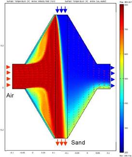
For dimensioning of the heat exchanger the FEM software Comsol Multiphysics was applied. In a 2-D simulation model the air flow field and heat transfer between air and sand are calculated. Here, the focus is on the sand domain between the two porous walls, and includes air inflow and outflow.
The heat transfer between air and sand and the air flow in the sand domain is represented by a homogeneous two-phase model without consideration of temperature distribution in the single sand grains. It is based on three differential equations, two of which describing the energy balance of air and sand and the third equation describing porous media flow based on Darcy’s law.
|
(1) (2) |
![]() cSPS (1 — s)"df = V • (.BedVTS) — csps (1 — S) • vs — VTS + f
cSPS (1 — s)"df = V • (.BedVTS) — csps (1 — S) • vs — VTS + f
dT
|
with f = hAv (TA — TS) |
|
f |
|
V — Pa |
|
nDyn, A |
|
dP A dt |
|
For the sand energy balance equation a fixed parabolic velocity profile for laminar sand flow is assumed. The air/sand temperature distribution and air flow field in inlet and outlet are shown in Fig. 3. The air and sand inflow temperatures are 800 °C and 200 °C, the sand grain size is 1 mm. The temperature field in the sand domain is featured by the typical cross-flow characteristic with a diagonal isothermal line. |
 |
 |
caPaS df = V • (aSVTA ) — caPaS • VA • VTA — f
Fig. 2 Steady state temperature and air flow field simulation
For dimensioning of the experimental heat exchanger set-up the following variables were analysed:
• Influence of heat exchanger dimensions on average output temperatures
• Heat conduction in sand and air
• Sand grain size
• Air velocity and sand velocity profile
1.2. Energy and Exergy
The operation of a typical TES can be separated into three key segments: charging, discharging, and storage. The energy balance within the TES adheres to First Law conservation of energy, such that:
tit t
|
(1) |
![]()
|
0 |
|
0 |
|
0 |
|
0 |
f Estored)dt = f Echarged(t)dt “ f ^schargedW^ “ f Elost(t)dt
|
riER (t) = |
|
E |
|
stored, real |
|
E. |
|
stored, ideal |
|
(0 (t) |
|
(2) |
 |
|
Elost(t) denotes the thermal energy lost to the surroundings. We otherwise ignore kinetic and potential energy effects. Early techniques for assessing thermal storage effectiveness consisted principally of First Law considerations [6], where the Energy Response (pER) of an experimental TES would be typically compared to an ideal system [1], such that:
|
£ stored (t) _ mstoredCp (^stored (t) T0 ) mstoredCpT0 ln |
|
T A |
It has been widely accepted that the energy response alone (a representation the First Law of Thermodynamics) cannot solely characterize a TES. Stratification, for instance, which is known to significantly improve the effectiveness of a thermal energy store [7], cannot be assessed using the First Law as it is a characteristic that describes how energy is stored in the tank, not the energy content itself. To incorporate stratification into a characterization scheme therefore requires the Second Law of Thermodynamics, which states that the optimal storage of useful energy in a TES is achieved when maximing the exergy stored [5], represented as:
T0 refers to the dead-state temperature at which work is to be performed. A review of TES characterization methods by Haller et. al. [8] further illustrates that the incorporation of Second Law figures of merit can improve the overall assessment of TES storage efficacy. The methods by Panthalookaran [1], Shah and Furbo [2], and Huhn (referenced in [8]) are particularly highlighted.
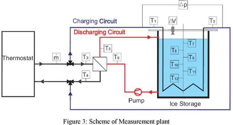
Part of the measurement campaign was to evaluate the performance of two types of heat exchangers under the same operating conditions, and to compare them with respect to technical and also economic aspects. For charging different charging temperatures form -12°C up to -2°C were chosen and measured. Discharging temperature ranged from 20°C to 24°C.
System A is a heat exchanger manufactured from copper with a heat transfer area of 5.5 m2. System B is manufactured from polypropylene, its heat transfer area is about 4 m2.
A test rig was built which is shown in Figure 3 including all measuring points and all measured variables.
|
|
In the following several experimental runs will be described and a short overview of measured results will be given.
The authors expect that the future will bring
• Limited resources of natural gas
• Increased demand for biomass to gas and liquids for the transport sector
• Increased windmill capacity (+photovoltaic and wavepower)
• Increased demand for electricity regulation
That means that heat production mainly has to come from renewable energy (not biomass) and “waste” heat from electricity regulation.
The most efficient systems to solve these problems are district heating systems. So a main part of the solution of the above mentioned problems will be
|
Solar Thermal systems have only recently become popular in the UK. Research shows that in the year 2000 only 151,000 m2 of water collectors (both flat plate and evacuated tube) were in operation in the UK [1]. This equates to <3 m2 of collector area per 1,000 inhabitants, which is significantly lower than countries like Greece (264 m2), Austria (198 m2), Denmark (46 m2), Switzerland (37 m2) and Germany (34 m2). There is a false impression, shared even amongst architects and designers, that there is insufficient solar energy in the UK to achieve solar fractions which would contribute significant energy savings and carbon reductions. This paper shows the solar thermal potential for Wales. Twelve house types, considered as representative of the entire Welsh Housing stock are modelled and the thermal energy demands for space heating, cooling and domestic hot water preparation for each house type are predicted. The share of the total thermal energy requirement that can be met by solar energy, instantaneously and by means of thermal energy storage techniques for each house type is analysed.
[1] Introduction
Solar pond is a simple and low cost solar energy system which collects solar radiation and stores it as thermal energy in the same medium for a long period of time. When solar radiation penetrates on the solar pond surface, the infrared — radiation component will be firstly absorbed rapidly in the surface mixed layer. However heat loses to the atmosphere by convection and radiation. The remaining radiation will subsequently be absorbed party in the non — convective zone before the last of the radiation reaches the bottom of the pond. The saline concentration in this layer is higher than the others. The more obvious application for solar ponds are for heating and cooling of buildings, power production and desalination.
The first recorded solar pond to a natural solar lake was that of Kalecsinsky who decribed the Lake Madoc (Medie Lagoon), located at (42 ° 44’N,28 ° 4 5’E ) in Transylvania This lake showed
[3] Conclusion
Composite material based on CENG and PCM has been directly implemented behind a solar absorber. The insertion of this composite provides new storage functionality to the collector. A MUE of 0.26 has been found and considering the efficiency of the solar absorber, 67 to 89% of the solar energy collected has been stored. The high conductivity of the storage composite gives rise to a high level of power restitution of the stored energy.
A numerical model had been developed for charge and discharge processes. Comparison between experimental and simulated temperature profile allowed us to validate this model.
Nomenclature
Table 1. Nomenclature, greek symbols and superscripts.
Nomenclature
A Area (m2) Cp Calorific capacity (J. kg-1.K-1)
[5] Introduction
[6] Description of the Alstonvale Net Zero House
2.1. Existing testing facility
In 2003 a testing facility was installed at the institute which basically circulates the slurry between two counter flow plate heat exchangers. In one of them the material is cooled (transition to solid phase) in second heat exchanger the material is melted again.
This facility offers the possibility to determine the following physical properties under operation:
— Heat capacity
— The range of melting temperatures
— Thermal and mechanical cycle stability
— Subcooling[14]
— Heat transfer coefficient
— Pressure drop
Additionally this facility allows the testing of the influence of the liquid on standard hydraulic components such as conventional plate heat exchangers, centrifugal pumps, membrane expansion vessels, breathers and valves. [6]
C. A. Cruickshank1* and S. J. Harrison1
1 Solar Calorimetry Laboratory, Department of Mechanical and Materials Engineering, Queen’s University,
Kingston, ON, K7L 3N6, CANADA
Corresponding Author, cruickshank@mc. quccnsu. ca
Abstract
The thermal response of a series-connected multi-tank thermal storage was studied under variable charge conditions. Tests were conducted on an experimental apparatus consisting of three 270 L storage tanks, connected in series and each charged through a coupled, side-arm, natural convection heat exchanger. Both energy storage rates and temperature profiles were experimentally measured during charge periods consisting of two consecutive clear days or combinations of a clear and overcast day. Of particular interest was the effect of rising and falling charge loop temperatures and collector-loop flow rate on storage tank stratification levels. Results of this study show that the series connected thermal storage reaches high levels of temperature stratification in the storage tanks during periods of rising charge temperatures and limits destratification during periods of falling charge temperature. This feature is a consequence of the series connected configuration that allows sequential stratification to occur in the component tanks and energy distribution according to temperature level. A further aspect of the study investigated the effect of increasing charge — loop flow rate on the temperature distribution within the storage system during a simulated charge sequence. Temperature distributions measured during high flowrate tests were found to be similar to those obtained during parallel charging of the storage system. This final result is consistent with expected theory. A disadvantage for both the high-flow series — connected and parallel connected multi-tank storage is that falling charge-loop temperatures that normally occur in the afternoon tend to mix and destratify the storage tanks.
Keywords: Solar energy, thermal storage, stratification, multi-tank
1. Introduction
This paper builds on previous studies undertaken to investigate the operation of medium capacity, multi-tank thermal storages connected in both series and parallel configurations. Multi-tank storage schemes have been previously investigated [1-5]. A multi-tank thermal storage with immersed-coil heat exchangers was originally proposed by Mather et al., [1] and showed to sequentially thermally stratify during charging. More recently, a series-connected thermal storage, Fig. 1, in which the individual storage tanks are charged through natural convection heat exchangers (NCHE’s), has been studied [2-5]. In this arrangement, each NCHE can charge its associated storage tank in a fashion similar to a traditional thermosyphon [2]. As well, the charging of the individual storage tanks is self-regulating (i. e., each acts as a thermal diode) and selfdistributing (i. e., the energy from lower temperature charge periods is directed to lower temperature downstream tanks). This sequential stratification maintains higher temperatures in the thermal storage by avoiding destratification during cooler charge periods or the removal of energy from the upstream tanks to the downstream storage tanks (i. e., “thermal carry-over”). Under ideal
|
Fig. 1. Series-connected, multi-tank storage configuration studied. |
|
Fig. 2. Experimental test apparatus (prior to insulating). |
 |
 |
operation, maximum thermal stratification is obtained in the storage system. In real systems, however, non-ideal conditions exist including: a finite number of storage tanks; limited heat transfer rates in the heat exchangers; and non-adiabatic storage tank walls and piping, etc. In addition, reverse thermosyphoning due to adverse temperature gradients in the heat exchanger or thermosyphon loop may result in destratification. Thermal carry-over may occur during periods of falling charge temperatures, i. e., in the afternoon or during periods of low solar input.
To investigate these effects, a multi-tank thermal storage, Fig.2, was assembled in a laboratory environment to allow tests to be conducted under controlled charge conditions representative of combinations of clear and cloudy days. Data obtained included temperature profiles within the storage tanks (recorded as a function of charge duration) and energy transfer rates in the individual heat exchangers. The description of the system, the test apparatus and results are presented below.