Как выбрать гостиницу для кошек
14 декабря, 2021
Сегодня каждый, кто собирается в отпуск и не знает, с кем оставить своего котика или кошку, может во[...]
1.1 Simulation model
For dimensioning of the heat exchanger the FEM software Comsol Multiphysics was applied. In a 2-D simulation model the air flow field and heat transfer between air and sand are calculated. Here, the focus is on the sand domain between the two porous walls, and includes air inflow and outflow.
The heat transfer between air and sand and the air flow in the sand domain is represented by a homogeneous two-phase model without consideration of temperature distribution in the single sand grains. It is based on three differential equations, two of which describing the energy balance of air and sand and the third equation describing porous media flow based on Darcy’s law.
|
(1) (2) |
![]() cSPS (1 — s)"df = V • (.BedVTS) — csps (1 — S) • vs — VTS + f
cSPS (1 — s)"df = V • (.BedVTS) — csps (1 — S) • vs — VTS + f
dT
|
with f = hAv (TA — TS) |
|
f |
|
V — Pa |
|
nDyn, A |
|
dP A dt |
|
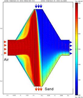
For the sand energy balance equation a fixed parabolic velocity profile for laminar sand flow is assumed. The air/sand temperature distribution and air flow field in inlet and outlet are shown in Fig. 3. The air and sand inflow temperatures are 800 °C and 200 °C, the sand grain size is 1 mm. The temperature field in the sand domain is featured by the typical cross-flow characteristic with a diagonal isothermal line. |
 |
 |
caPaS df = V • (aSVTA ) — caPaS • VA • VTA — f
Fig. 2 Steady state temperature and air flow field simulation
For dimensioning of the experimental heat exchanger set-up the following variables were analysed:
• Influence of heat exchanger dimensions on average output temperatures
• Heat conduction in sand and air
• Sand grain size
• Air velocity and sand velocity profile