Как выбрать гостиницу для кошек
14 декабря, 2021
Instchemas AB, Sweden,
iulius. evem@glocalnet. net.
A heating system for family houses, consisting of directly connected solar heat collector (SHC) and heat pump was designed. The connection makes it possible to utilize both direct solar irradiation and heat contained in the moist air during periods without solar radiation. The designed system contains seasonal heat storage magazine consisting of the pit filled with a humid soil. The dense placement of the heat collector in the pit causes freezing of the water, which contributes to high content of usable energy, more than 40 kWh/m3 of the soil. The frozen soil is melted in the spring by means of warm brine from the SHC.
Keywords: solar heat collector, heat pump, latent heat, phase change material, heat storage magazine.
Solar radiation is the most abundant energy source on Earth. In spite of that, it is not used in large extent for covering useful energy demands of the human population. The diurnal and seasonal cycle of the solar radiation may be one of reasons, even though the wind energy, which is much less predictable and mainly much less dense energy source, is greatly subsidized in EU countries. While the energy density of the wind does not exceed 5-10 W/m2 and the accessibility generally does not come up to 30-35% of the annual time, the insolation can deliver more than 1 kW/m2 (heat) or ~50 W/m2 (electricity) with the accessibility in some areas more than 35% of the annual time.
The diurnal and at latitudes above 23° the seasonal variations of the insolation require storage of the solar energy in magazines with seasonal heat capacity.
There are principally two kinds of energy storage types: the chemical and the physical one. Quantitatively, some storage modes are suitable for large scale capacity storage, (GWh — TWh) some for the middle scale (1 — 1000 MWh) and others have just small scale capacity (less than 1 MWh).
To achieve further technical development numerous conditions were discussed, where the governmental power to influence consumers’ choice of system was stressed; the government should clearly point out the political standpoint in energy issues, and to be valid more than one term of office it should preferably be disconnected from party politics. This standpoint could be conveyed for example by the municipal energy advisors and the Swedish Energy Agency, but also by making longterm regulations about heating in new buildings. The legislation in some countries, where solar collectors must be installed in new-build residential buildings, and wishes for similar legislations in Sweden were often mentioned. The influence of politicians and celebrities on the costumers was stressed, and several informants wished for those to show their attitudes in the issue, to act role models. But above all, the market has to be predictable; the companies have to know what conditions will be valid also in the long run and what subsidies there will be, to avoid strong declines, as that from which the pellet industry suffers at present.
The reliability of the systems, with focus on the pellet boilers, must be improved; “the technique has to keep its promises”. The system solution has to offer comfortable and secure heating, but also a reliable solution. Both solar collectors and pellet burners were traditionally often home-made in study circles or by inventors “in the bushes” and the technique was sometimes not well-functioning, resulting in bad reputation, which recoils on the trade as a whole. In addition, the systems have to be well-designed; undergo an aesthetical improvement to visually attract people. As one informant expressed it “we can make it cool, make it in fashion, trendy. Just like the Germans, Austrians, where you are proud of your pellet plant and your solar plant because you are environmental-friendly.” The necessity of easily operated systems is pointed out as a main issue, often in comparison to the success of heat pumps.
“The consumer of today only wants to press a button and nothing more, and if one [system supplier] does not realize that one makes a demand on the costumer that the common man does not want”.
One of the prime issues to reach out is better economical conditions to enable increased marketing, and thereby become visible. Most costumers do not know enough about the systems or the problems and possibilities with different heating systems in general. The marketing has to be more professional and it would be advantageous for the solar and pellet trade to cooperate to reach out with neutral information, preferably supplied by independent organizations or authorities. The success of the heat pumps and how to reach the same position for solar and pellet systems were mentioned in more or less every interview. Some informants talked about heat pumps as the evil enemy; while most interviewees focused on how to learn from their success. The difficulty in competing with the heat pump industry was however obvious due to the large difference in economical assets. The problem so far has been the small solar and pellet companies, but there is a belief in a change in the near future, when larger actors with larger monetary assets are getting increased interested in those issues.
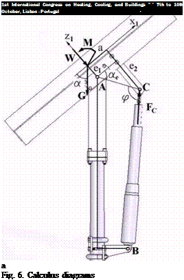
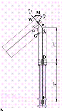
Figure 7 presents the calculus diagram for the reactions in the seasonal rotational axis and in the linear actuator (a) and in the bearings of the vertical axis (b). The reaction in the linear actuator is calculated with relation
М + Ge, cosa)cosae
Fc =- — -, (1)
a sin ф
negative values mean tension on the actuator’s screw. The reactions in the A axis are:
![]() F-a = G cos a — Fc cos^-a e); Fz1A = W + G sin a — Fc cos^- a e)
F-a = G cos a — Fc cos^-a e); Fz1A = W + G sin a — Fc cos^- a e)
and the reactions in the bearings of the A axis are:
![]()
 |
 |
RA’= Ra»= ^ ^ ; FaA = 0.
The reactions in the vertical axis are:
![]() FaD = W sin a + G.
FaD = W sin a + G.
The optimal design of a linkage mechanism like the one involving the linear actuator is looking for symmetrical extreme positions C and C2 of the C link, relative to the less loaded position with ф = 90°, in order to obtain proper ф pressure angles.
Figure 7 presents the extreme positions of the linear actuator mechanism. Based on fig. 7, the following relations have been established:
 rn = 90° + -(amx—• ф . = 90° —
max min

|
|
|
|
|


Fig. 8. Main reactions on bearings and linear actuator
Based on the results presented above, the following conclusions can be drawn:
• The radial loads on the bearings of the vertical axis (RD and RE) are clearly depending on the wind case considered; biggest values are obtained for wind case 1 (for front wind), respectively wind case 4 (for back wind) and the smallest values are obtained for wind case 2 9for front wind), respectively wind case 5(for back wind); Same observations are valid for the axial force on the vertical axis (FaD) more clear for the loading case 2 (fig. 8, b);
• The force on the A bearings (RA) is bigger for wind case 2 (for front wind), respectively wind case 5 (for back wind) and smaller for wind case 1 (for front wind), respectively wind case 4 (for back wind);
• The axial force in the actuator’s screw is always negative meaning tension on the actuator and is is bigger for wind case 2 (for front wind), respectively wind case 5 (for back wind) and smaller for wind case 1 (for front wind), respectively wind case 4 (for back wind);
• Loading case 1 (summer solstice — noon) gives the biggest radial load RD;
• Loading case 2 (winter solstice — noon) gives the biggest axial load FaD and biggest force on the A bearings (Ra);
• Radial load RD is slightly different between the two loading cases;
• Load on the screw’s actuator is maximum for the two extreme loading cases;
• The permissible axial load on the actuator is few times bigger than the maximum load for the extreme loading case, even if the actuator is the smallest of its class. Anyway, normal solar tracker systems have bigger dimensions than the tracker presented in this paper, using actuators at their permissible load [9]. Considering the geometry of the linkage mechanism with actuator, the axial load on the actuator’s screw is increasing with the decrease of actuator stroke.
[1] R. N. Clark, B. D. Vick, Performance Comparison of Tracking and Non-Tracking Solar Photovoltaic Water Pumping Systems, Presentation at the 1997 ASAE Annual International Meeting Minneapolis, Minnesota (1997). http://www. cprl. ars. usda. gov/REMM Publishers. htm.
[2] I. Visa, D. Diaconescu, V. Dinicu, B. Burduhos, The Incidence Angles of the Trackers Used for the PV Panels’ Orientation. Part I: Part II: Azimuthally Trackers (2007), International Conference on Economic Engineering and Manufacturing Systems RECENT, Vol. X, Brasov.
[3] NP-082-04. Eurocode 1. Design Code. Bases of Design and Actions on Buildings. Action of Wind. Monitorul oficial al Romaniei.
[4] A. Roger, J, Messenger, Photovoltaic Systems Engineering (2004), CRC Press, Boca Raton.
[5] C. I. Co§oiu, A. Damian, R. M. Damian, M. Degeratu, Numerical and experimental investigation of wind induced pressures on a photovoltaic solar panel (2008) International Conference on Energy, Environment, Ecosystems and Sustainable Development, Algarve, Portugal.
[6] B. Sorensen, Renewable Energy (2004), Elsevier Academic Press.
[7] S. Blackman, R. Popoli, Design and Analysis of Modern Tracking Systems (2000), Artech House Publishers, Boston.
[8] G. Pahl, W. Beitz, Engineering Design (1995), Springer, London.
[9] R. Velicu, G. Moldovean, C. C. Gavrila, Constructive Aspects on the Altitudinal System of a Solar Tracking PV Platform (2008). International Conference on Sustainable Energy, Bra§ov, Romania.
The thermal performance of bikini solar combisystems is investigated for the Task 26 DHW profile for different H/D ratios of the tank. The insulation thickness is the same for all H/D ratios. The heat transfer area of the top and the bottom mantle is constant for all H/D ratios and the auxiliary set point temperatures are 55, 60 and 75°C for the low energy house, the house with medium space heating demand and the old houses. Fig. 7 shows net utilized solar energy for three different space heating systems with three different collector areas and H/D ratios of the tank. The H/D ratio of the tank does not play an important role when the heat transfer area is the same for all H/D ratios as long as the H/D ratio is higher than 2. For 3 m2 solar collector area a decreased space heating load results in an increased thermal performance of the system. This is due to the decreased set point temperature for the low space heating demands. For a collector area of 5 m2, the thermal performance in the house with the medium space heating demand is a little bit higher thermal performance of the system in the low energy house while the system has the lowest thermal performance in the old house. For a collector area of 8 m2, the thermal performance of the solar heating system in the house with medium space heating demand is a little higher than the thermal performance of the system in the house with low energy demand and higher than the thermal performance of the system in the old house.
|
H/D |
=2, |
Coll |
area= |
3 m2 |
|
H/D |
=3, |
Coll |
area= |
3 m2 |
|
H/D |
=4, |
Coll |
area= |
3 m2 |
|
H/D |
2, |
Coll |
area= |
5 m2 |
|
H/D |
3, |
Coll |
area= |
5 m2 |
|
H/D |
4, |
Coll |
area= |
5 m2 |
|
H/D |
2, |
Coll |
area= |
8 m2 |
|
—— H/D |
3, |
Coll |
area= |
8 m2 |
|
—— H/D |
4, |
Coll |
area= |
8 m2 |
![image121 Подпись: Space heating load [kWh/year]](/img/1155/image121_0.gif) |
Fig. 7. Net utilized solar energy versus H/D ratio for the bikini solar combisystem
Two-positional tracking for a stand-alone PV-module (or solar thermal collector) is always profitable in terms of produced energy. A solar farm in the regime of the two-positional tracking always produces more energy than a fixed one, considering the area of the modules. While considering the area of installation, two-positional tracking may be problematic, while the density of the modules cannot be high. At high latitudes, two-positional tracking is preferred for highly tilted modules, especially for facade farms. If the economy of the capital cost of the PV-modules is preferred, the two-positional exposure of these may be recommended. If the facade of a dwelling should be utilized highly, the PV-modules should be installed traditionally on the wall. Naturally, architectural recommendations should be considered.
• A solar PV-farm that uses the two-positional tracking of modules about their axes is effective if the distance between the axes is larger than the two-three widths of the modules concerned.
• The estimated average gain of a vertical solar PV-farm with the two-positional tracking is 10-20% compared with the fixed one and depends on the relative distance between the modules and their deflection angle.
• The average gain of a solar PV-farm with the two-positional tracking is 5-10% less than that of a stand-alone PV-module at the same deflection angle.
The author thanks the Estonian Science Foundation for their support, grant 6563.
[1] Teolan Tomson, Discrete two-positional tracking of solar collectors, Renewable Energy, 33 (2008) 3, 400-405.
[2] D. Weinstock, J. Appelbaum, Optimal Solar Field Design of stationary Collectors, Transactions of the ASME, vol. 126 (2008) 898-905.
[3] D. Weinstock, J. Appelbaum, Optimization of Economic Solar Field Design of Stationary Thermal Collectors. Journal of Solar Energy Engineering, vol. 129 (2007) 363-370.
[4] Russak, V., Kallis, A., (2003). Handbook of Estonian Solar Radiation Climate, Ed. by H. Tooming,
EMHI, Tallinn.
[5] Solar Energy. The state of the art, (2001). Ed by J. Gordon, James & James, London, p. 194.
[6] Duffie, J. A. and Beckman, W. A., Solar Engineering of Thermal Processes, (2006), J. Wiley & Sons INC, Hoboken, NJ, USA.
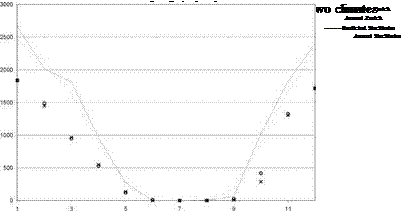 |
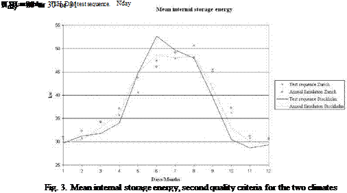
The process presented above was applied to elaborate the test sequences for two climates: Zurich and Stockholm.
 |
|
The predicted monthly values of the space heating demand are computed as follow:
The test sequences were optimised for the following reference conditions:
• a reference solar combisystem design with the following characteristics : the collector area is 12m2 and the heat storage volume is 600 litres,
• a reference building with 60 kWh/m2 heating demand in Zurich conditions (referred as SFH60).
These reference conditions come from IEA Solar Heating & Cooling programme Task 32 [6].
|
The selected days for the two test sequences are listed in the following table.
Table 2. Test sequences days. |
The two solar heating systems have been tested under the same test conditions in the test period March 8, 2008 — July 7, 2008: The solar radiation on the two collectors is the same and the hot
water consumption and hot water consumption pattern are the same for both systems. Daily a hot water volume of 100 l, heated from 10°C to 50°C, is tapped from each tank. Hot water is drawn from the tanks at 7 am, at noon and at 7 pm in three equally sized volumes. The hot water consumption is 32.2 kWh per week.
The tapped energy, the auxiliary energy, the solar heat transferred to the heat storage, the operation time of the circulation pump, the pump energy and the heat loss from the cold and hot part of the solar collector loop are measured for each system during the whole test period. Due to problems with the monitoring system measurements were not carried out for one week during the test period.
The measured results are shown in table 2. The net utilized solar energy is the tapped energy minus the auxiliary energy transferred to the top of the tank by means of the electrical heating element. The solar fraction is the ratio between the net utilized solar energy and the tapped energy.
Table 2. Measured energy quantities in the test period March 8, 2008 — July 7, 2008.
|
Measured energy |
Solar heating system with lifeline and SOLAR 15-65 |
Solar heating system with normal solar collector loop and SOLAR 15-40 |
|
Solar radiation on solar collector |
3490 kWh |
3490 kWh |
|
Tapped energy |
515 kWh |
515 kWh |
|
Auxiliary energy to top of tank from electrical heating element |
158 kWh |
163 kWh |
|
Solar heat transferred to hot water tank |
478 kWh |
459 kWh |
|
Net utilized solar energy |
358 kWh |
353 kWh |
|
Solar fraction |
69% |
68% |
|
Operation time of pump |
913 h |
873 h |
|
Pump energy |
32.6 kWh |
18.3 kWh |
|
Heat loss from solar collector loop, from collector to tank |
77 kWh |
94 kWh |
|
Heat loss from solar collector loop, from tank to collector |
33 kWh |
76 kWh |
|
It is seen that the thermal performance of the solar heating system with the lifeline and the SOLAR 15-65 pump is 1% higher than the thermal performance of the solar heating system with the normal solar collector loop and the SOLAR 15-40 pump. |
Figure 3 shows the performance ratio, defined as the ratio between the net utilized solar energy for the solar heating system with the lifeline and the SOLAR 15-65 pump and the net utilized solar energy for the solar heating system with the normal solar collector loop and the SOLAR 15-40 pump as a function of the solar fraction for the solar heating system with the normal solar collector loop and the SOLAR 15-40 pump. Each point in the figure represents the performance ratio for one week. For instance, a point with a solar fraction of 0.85 and a performance ratio of 1.02 corresponds to a week where the thermal performance of the solar heating system with the lifeline and the SOLAR 15-65 pump is 2% higher than the thermal performance of the solar heating system with the normal solar collector loop and the SOLAR 15-40 pump and where the solar heating system with the normal solar collector loop and the SOLAR 15-40 pump covers 85% of the hot water consumption.
The extra thermal performance of the solar heating system with the lifeline and the SOLAR 15-65 pump is influenced somewhat by the solar fraction. For most weeks, the extra thermal performance is increasing for decreasing solar fraction. However, for some weeks it is the other way around. It is also seen that the pump energy for the system with the lifeline and the SOLAR 15-65 pump is higher than the pump energy for the system with the normal solar collector loop and the SOLAR 15-40 pump. The extra pump energy for the SOLAR 15-65 pump is higher than the extra net utilized solar energy for the system with the lifeline and the SOLAR 15-65 pump. Consequently, the use of the lifeline and the SOLAR 15-65 pump is not justified from a thermal performance point of view.
0.80
0.00 0.10 0.20 0.30 0.40 0.50 0.60 0.70 0.80 0.90 1.00
Solar fraction of the system with the normal solar collector loop and the SOLAR 15-40 pump, [-]
Fig. 3. Performance ratio for the solar heating system with the lifeline and the SOLAR 15-65 pump as a
function of the solar fraction of the solar heating system with the normal solar collector loop and the SOLAR
15-40 pump.
![image145 Подпись: Figure 6 shows the power supply from the solar collector fluid to the tanks of the two systems during March 28, 2008. There are not large differences between the two systems. 07:00 08:00 09:00 10:00 11:00 12:00 13:00 14:00 15:00 16:00 Time, [h:m]](/img/1155/image145_0.gif) |
Figure 4 shows the solar irradiance on the solar collectors on a cloudy day, March 28, 2008. Figure 5 shows the measured volume flow rates in the solar collector loops and the pump powers for the two systems March 28, 2008. The pumps are in operation in two periods, one from about 7:45 am to 11:45 am and one from about 12:15 pm to 15:45 pm. The volume flow rates in the solar collector loops are increasing during the operation periods. This is first of all caused by the increasing solar collector fluid temperatures. Further, relatively low volume flow rates are observed in the very start of the operation periods. This is caused by the fact that the solar collector fluid is heated to relatively high temperatures in the solar collectors during the stand by periods. When the pump is first activated the solar collector fluid with the high temperature is pumped into the pipe going downwards from the solar collector to the tank. At the same time relatively cold solar collector fluid from the mantle is pumped into the pipe going upwards from the tank to the solar collector. The density difference between the cold and the hot solar collector fluid in the two pipes is relatively large in the start-up phase due to the “overheated” solar collector fluid in the solar collectors. The pumps must overcome the pressure drops caused by these density differences. Therefore the volume flow rates are especially low in the start-up phase. It is also noticed that the pump powers are decreasing during the operation period. This is especially true for the SOLAR 1565 pump.
Fig. 4. Total solar irradiance on solar collectors, March 28, 2008.
 |
Figures 7 and 8 show the measured solar collector fluid temperatures in the two systems March 28. It is seen that the difference between the heat loss from the hot pipes for the two systems is small and that the heat loss from the cold pipe in the system with the lifeline is small compared to the heat loss from the cold pipe for the other system. The small heat loss of the cold pipe results in a relatively high inlet temperature to the solar collector and thereby in a somewhat reduced collector efficiency. Therefore the thermal advantage by the low heat loss from the cold pipe of the lifeline is limited.
Fig. 7. Measured solar collector fluid temperatures in the solar collector loop for the system with the normal
solar collector loop and the SOLAR 15-40 pump March 28, 2008.
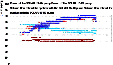
![image147 Подпись: Figure 9 shows for March 28 the pump powers and volume flow rates in the solar collector loops for the two systems as a function of the solar collector fluid temperature passing the pumps. The volume flow rates are increasing and the pump powers are decreasing for increasing temperatures. The volume flow rates are almost the same for the two systems. The volume flow rates varies from about 0.3 to 0.6 l/min and the pump powers are about 20 W for the SOLAR 15-40 pump and varies from about 45 to 30 W for the SOLAR 15-65 pump. Time, [h:m] T1 Sol-col-out 0 T2 Sol-hx-in T3 Sol-hx-out T4 Sol-col-in](/img/1155/image147_0.gif) |
Fig. 8. Measured solar collector fluid temperatures in the solar collector loop for the system with the lifeline
 |
|
and the SOLAR 15-65 pump March 28, 2008.
10 15 20 25 30 35 40 45
Temperature of fluid passing the pump, °C
Fig. 9. Measured pump powers and volume flow rates as a function of the temperature of the solar collector
fluid leaving the mantle for the two systems March 28, 2008.
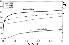
Influence of building integrated solar collectors on indoor environment and building performance has been evaluated. Specific winter heat gains and summer cooling loads have been obtained from annual space heating demand and space cooling demand of the investigated building with envelope direct integrated collectors compared to the reference case without collector integration. The characteristics of specific heat gains Aqsh and cooling loads Aqsc are plotted in dependence on collector-envelope (roof, faqade) coverage area ratio Ac/Ae in Fig.5 for atmospheric, evacuated and vacuum solar collectors integrated into building envelope (roof, faqade) operated in combisystems
with different operation temperatures for space heating. Heat gains from the collectors integrated into the facade achieve during the heating season, depending on supply temperature, about 2.3 to
3.5
 |
 |
% of heating demand for combisystem with 10 m2 collector area and 12.2 to 15.5 % of heating demand for total facade coverage (Ac = 42 m2). For the roof integrated case the impact is slightly higher (2.6 to 3.8 % for Ac = 10 m2 and 13.5 to 16.7 % for the extreme case of total roof coverage).
 |
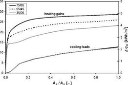 |
Fig.5a. Collector induced specific gains and loads to building due to integration of atmospheric flat-plate collector into the building envelope (roof integration on the left side; facade integration on the right side).
 |
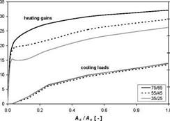 |
Fig.5b. Collector induced specific gains and loads to building due to integration of evacuated flat-plate
collector into the building envelope (roof integration on the left side; facade integration on the right side).
Fig.5c. Collector induced specific gains and loads to building due to integration of vacuum flat-plate
collector into the building envelope (roof integration on the left side; facade integration on the right side).
Due to high heat resistance of the envelope (low-energy house) the influence of solar collector integration does not bring large problems for summer overheating. For the most extreme case where the south roof of the building is completely covered by vacuum flat plate collectors (Ac = 42 m2) the cooling load is less than 150 kWh/season.
Similar results are illustrated in Table 2, this time presenting the specific heat gains and cooling loads induced by different types of collectors integrated into the building envelope (roof, facade) and different supply temperatures for space heating for a given solar fraction off = 30 %. It shows that more efficient collectors (vacuum) have higher influence on the building environment than standard atmospheric flat-plate collectors. Furthermore, less collector area is needed to achieve the same solar fraction. The lower the supply temperature of the heating system the better is the performance of the combisystem (less collector area achieving same solar fraction) and the less impact on the building performance can be expected.
Table 2. Specific heat gains Aqsh and cooling loads Aqsc induced by investigated envelope integrated flat-
plate collectors for solar fraction f = 30 %. The required collector area for f = 30 % is shown.
|
AS |
AR |
AF |
|||||
|
Ac |
Aqsh |
<1 |
Ac |
Aqsh |
<1 |
Ac |
|
|
m2 |
kWh/m2 |
kWh/m2 |
m2 |
kWh/m2 |
kWh/m2 |
m2 |
|
|
75/65 |
11.9 |
22.9 |
1.8 |
10.0 |
23.9 |
1.3 |
11.2 |
|
55/45 |
10.8 |
17.8 |
1.4 |
9.3 |
18.4 |
1.0 |
10.4 |
|
35/25 |
9.7 |
13.1 |
1.0 |
8.6 |
13.1 |
0.7 |
9.6 |
|
ES |
ER |
EF |
|||||
|
Ac |
Aqsh |
<1 |
Ac |
Aqsh |
<1 |
Ac |
|
|
m2 |
kWh/m2 |
kWh/m2 |
m2 |
kWh/m2 |
kWh/m2 |
m2 |
|
|
75/65 |
10.1 |
22.1 |
2.6 |
8.4 |
22.5 |
1.7 |
9.4 |
|
55/45 |
9.4 |
17.8 |
2.1 |
8.0 |
17.8 |
1.4 |
9.0 |
|
35/25 |
8.7 |
13.7 |
1.6 |
7.7 |
13.3 |
1.0 |
8.6 |
|
VS |
VR |
VF |
|||||
|
Ac |
Aqsh |
<1 |
Ac |
Aqsh |
<1 |
Ac |
|
|
m2 |
kWh/m2 |
kWh/m2 |
m2 |
kWh/m2 |
kWh/m2 |
m2 |
|
|
75/65 |
8.4 |
22.8 |
4.2 |
7.5 |
22.7 |
2.5 |
8.3 |
|
55/45 |
8.0 |
18.5 |
3.4 |
7.2 |
17.5 |
1.8 |
8.0 |
|
35/25 |
7.6 |
15.0 |
2.8 |
7.0 |
14.3 |
1.6 |
7.8 |
Parametric simulation analyses of solar combisystem configurations operated to different types of heating systems and equipped with atmospheric, evacuated and vacuum solar flat-plate collectors integrated into the building envelope or applied separately have been performed. For the solar combisystems the analyses have proved the advantage of building integration of solar collectors. Direct integration of solar collectors thermally coupled to the roof envelope results in higher performance when compared to faqade collectors but leads also to considerably higher stagnation levels and specific stagnation time due to unutilisable summer irradiation peak.
Direct facade collector integration compared to separate installation of solar collectors on the roof (thermally uncoupled) results in lower or equal collector area needed to achieve similar solar fractions but with considerably reduced stagnation periods. The operation temperature of a heating system affects the combisystem efficiency and should be maintained as low as possible for effective use of storage tank although evacuated solar collectors are applied.
The influence of building integrated solar collectors on indoor environment and building performance has been evaluated by means of specific heat gains in winter and cooling loads in summer both induced by heat flow from solar collectors into the building interior. Due to high thermal protection of low energy houses the influence of solar collector integration does not bring large problems for summer overheating even for extreme cases and brings very low heat gains in winter even for high-performance evacuated solar collectors.
The research work has been supported by a Marie Curie Early Stage Research Training of the European Community’s 6th Framework Programme under the contract MEST-CT-2005-020498: SOLNET and by research project CTU 880590 “Experimental validation of mathematical model for flat-plate evacuated solar thermal collector”
[1] European Solar Thermal Technology Platform, Solar Thermal Vision 2030 document, http://www. esttp. org. 2006.
[2] T. Matuska, Advanced Solar Collectors for Building Integration, Proc. of World Renewable Energy Congress X, Glasgow, Great Britain, 2008.
[3] T. Matuska, B. Sourek, Solar Systems with Facade Integrated Solar Collectors, ISES Solar World Congress 2005, Orlando, USA, 2005.
[4] J. Metzger, T. Matuska, B. Sourek, Solar Combisystems with Building-Integrated Evacuated Flat-Plate Solar Collectors, ISES Solar World Congress 2007, Beijing, China, 2007.
[5] T. Matuska, V. Zmrhal, Software tool KOLEKTOR 2.2, available from http ://www. fsid. cvut. cz/~matuskat/kolektor. htm
[6] TRNSYS 16 release. User’s manual. Wisconsin University. 2004.
The chemical conversion of the solar radiation to the useful, easily transportable energy carrier belongs to large scale storage modes and is based mainly on two processes. The first one is the photosynthesis of biomass from carbon dioxide (CO2) and water. The reaction is supposed to be CO2 neutral, which means that the speed of releasing the CO2 into the atmosphere during energy retrieval from the biomass equals the CO2 consumption rate during the photosynthesis of the biomass. Unfortunately, this assumption is not fulfilled in the present time.
The second process, able to convert insolation to useful energy carrier, is the reduction of CO2 to methanol. Following scheme shows principles of the process:
![]() + 3 H2O ^3 H2 +1У2О2 ; 3H2 + CO2 = CH3OH + H2O. (1)
+ 3 H2O ^3 H2 +1У2О2 ; 3H2 + CO2 = CH3OH + H2O. (1)
Neither water electrolysis nor methanol synthesis from CO2 are unknown processes [1]. Solar-thermal-electric systems (STES) are commercially available [2] and can produce enough electric current for large scale water electrolysis. CO2, instead of dumping it to Earth cavities after removing it from stack gases of power plants, can be easily transported in the liquid form to hydrogen production plants. Methanol, extremely versatile energy carrier, is a liquid, easily transportable. Water is partially recirculated in the process. Methanol plants can be therefore situated in rare populated areas, rich in solar radiation. And the process is 100% CO2 neutral.
The costumers bringing pressure on the building companies by demanding certain heating systems was identified as very useful in gaining market shares. The costumer has probably reached further than the building trade in the awareness of those systems; costumers ask for systems that the installer or
plumber is not willing or able to deliver. And due to that demand, companies work on system development at present. If you can not offer what the costumer wants, you will loose him. But, as one informant expressed it: “the costumer is so easily influenced, when the plumber says that he should have a heat pump, he believes in that”. The costumers must learn to assert themselves. By making the installer aware of other companies offering a certain type of systems, the costumer will force the installer to offer the same system solution. And that in turn affects the current assets of the supplier positively, causing growing companies, which in turn increases the interest from the installer, who can serve the costumer. This interplay sets the development going. But without demand and pressure from the market and costumers, the installers will not focus on those systems, but will continue with what they are already good in; they will “take the easy way out”. “If [the installer] has heard once [that someone wants a solar and pellet system] he says that it does not pay, but if he hears it ten times the same day […], he realises […] that he also has to offer it”.
Satisfied costumers are the best way to increase the selling rate, since they tend to tell neighbours and friends about their experiences. The opposite is however also valid, and has been a problem so far. Particularly some of the early pellet systems have been experienced as causing lots of trouble and nonsatisfied costumers. And success will not be reached until the costumers’ requests are fulfilled.