Как выбрать гостиницу для кошек
14 декабря, 2021
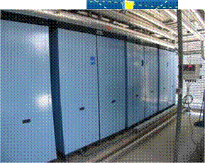
The central part of this building’s cooling system is a solar powered absorption cooling system made up of four 10kW state-of-the-art absorption heat pumps, driven by 90 high performance flat- plate solar collectors able to constantly deliver fluid at up to 95°C, the maximum temperature for the absorption heat pump to work properly. In summer this system is a serious alternative to conventional chillers or heat pumps for providing cold water to the cooling coils as it requires almost no additional energy (apart from the solar energy captured by the solar collectors) to cool the building. The absorption heat pump used at the Almeria building uses a patented technology that allows energy to be stored and instantly delivered later on. This way the system can store energy all along the sunny hours of the day and keep on cooling down the building even after sunset if necessary. It has to be mentioned that the system is designed so that it can store and deliver at the same time. Also, the technology employed allows the input fluid temperature to vary, as long as the temperature difference between the source and the heat sink (in our case a cooling tower for practical reasons) is above 50°C. When considering using solar thermal collectors as a heat source, this is an advantage over conventional absorption chillers that need the input fluid to remain at a constant temperature. The cooling tower can actually be controlled so that the absorption system keeps working even when the solar collectors’ output temperature falls down. On the other side, the system can also be set to take higher temperatures of up to 120°C for some minutes so that, in the end, this system makes it possible to take advantage of all of the available solar energy to produce cooling energy for the building.
 |
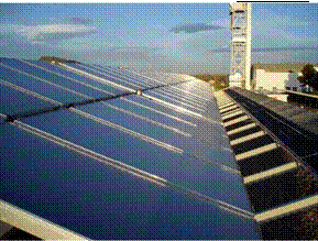 |
Fig. 1. Array of solar collectors on the roof (left) and Absorption heat pumps (right).
The main purpose of this study is the comparison between the performance of different concepts for DEC systems in Mediterranean climates. This comparison will be performed on a first and second law perspective; the analysis will be applied to the following systems: •
thermal load QL = 2.5 kW and a sensible thermal load QS = 7.5 kW. In Table 1 the design indoor and outdoor conditions are reported, as well as the inlet air conditions, determined by assuming an inlet air flow
ma = 1 kg/s (Va ~ 3200 m3/h); the regeneration air flow is equal to the process air. The design outdoor conditions are typical of a hot and humid climate, such as the one occurring in the countries of the Mediterranean area.
|
Table 1. Design conditions for the case study.
|
Thermal stability and fluid compatibility with materials as well as with lubricants in contact is a critical step in the design of an ORC plant. The working fluid must have a high thermal stability to provide the desired lifetime and a cost-effective plant. Care should be taken to make sure that the combination fluid/lubricant/material can assure a long lifetime period of the plant. Among the materials used are copper, steel and stainless steel just to name a few. The lubricant can be miscible or immiscible with cycle fluid, but for minimum system complexity miscible oil is desirable. Chemical decomposition of the fluid not only reduces the plant efficiency and makes the replacement of the fluid necessary but can produce noncondensable gases which have corrosive effects on the materials of the system. In order to study the fluids decomposition, two methods are available: the dynamic loop tests and the static capsule tests. The first method is the best but time-consuming and expensive. In general, to safeguard against plant damage from fluid decomposition, a combination of static capsule tests, large safety margins and field monitoring is usually employed. Wali [8], Calderazzi and Colonna di Paliano [9], Angelino and Invernizzi [10] are some authors who investigated the thermal stability of fluids. In Table 3 are displayed the maximum stability temperature of some fluids.
|
Table 3: Maximum stability temperature (MST) of some fluids
|
The silica gel machine is working at very low driving temperatures down to 65°C, but may not be used, when low water temperatures and high re-cooling temperatures are necessary. In order to achieve this temperature region SorTech AG is currently developing a second prototype chiller based on the same construction principles but using zeolite coated adsorbers.
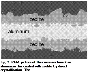
A new type of coating has been developed and filed for patent application by SorTech AG, which is based on a direct crystallisation of the zeolite on the surface of the heat exchanger (Fig. 5). Compared to the epoxy resin coating which is used in ACS 08 this new technology has the following advantages:
High mechanical stability of the coated layer due to strong binding forces at the interface zeolite — metal.
Fast adsorption kinetics, because of good heat and mass transport resulting from very compact layers, which contain only the active material.
 |
Reduction of material synthesis and coating to a one step process.
The feasibility of the direct crystallisation method has been shown by SorTech AG on small samples of aluminium fin material and on tube and fin heat exchangers. Currently we are working on the up-scaling of the process in a pilote plant as a first step for a later industrialisation.
Due to the reaction conditions of the zeolite (200 °C at 20 bars) the chemical engineering is a rather challenging task und is currently being performed.
Small compact adsorption chillers seem to be an attractive option for thermal driven air conditioning. The results of the field test of prototypes carried out in 2007 were encouraging. Therefore since March 2008 SorTech AG has introduced a small adsorption chiller ACS 08 with a chilled water capacity of 7.5 kW and since June 2008 a larger system ACS 15 with 15 kW into the market. Currently, we are producing our products in a small series and the market response is very positive.
The financial support from the German Federal Ministry of Economics and Technology (BMWi) is greatly acknowledged.
Second law analysis is a useful tool for the identification of irreversibilities and, in result, improvement potentials of thermal energy systems. Exergy enables the quantification of a system’s potential to perform work when brought in equilibrium with the environment. As opposed to energy, exergy can be destroyed. The exergy analysis of a thermal system therefore helps identifying the loss and destruction of available energy, identifying where the “true” potential to perform work is not exploited.
1.1 Exergy equations for the evaluation of HVAC cycles
The application of the exergy method to moist air processes such as air-conditioning, drying and wet cooling tower processes was first described by Szargut [4]. A pathbreaking publication for the application in HVAC was later written by Wepfer [5]. Processes of evaporative cooling [6,7] and rotary type desiccant systems [8,9] were later both covered. Equation 3 is the generally applied moist air specific exergy equation written on a per mass of dry air basis [4,5]:
[J/kg] (equation 3)
where the three terms give the thermal, mechanical and chemical exergy of moist air. An important issue for the application of exergy to moist air is the selection of the dead state. In the literature, both selecting either ambient conditions or saturated air at ambient temperature is discussed. The latter approach discussed by Chengqin [7] is followed in this paper, considering that unsaturated air still has a potential to perform work as it undergoes a temperature drop when humidified. Ideally, a Carnot engine could then be driven between the ambient air and the humidified air. According to equation 4, the moist air specific exergy is falling monotonously with rising moist air humidity ratio.
The exergy of water used for evaporation is generally described by equation 5 and is derived from analyzing a process where water is condensed from ambient air [5]:
= h(T) — h(To) — To[(T) — s(To)] ■+ [p — PSat (T)V(T) — RvT0 In Po [J/kg] (equation 5)
When choosing ambient temperature and humidity ratio as reference conditions, the last term is dominating. However, when choosing saturated air at ambient temperature as the dead state as followed here the last term drops out. For evaporative cooling schemes, the latter approach was found to give more reasonable results by the authors as the evaporation of water would otherwise be insensibly penalized.
The overall reaction rate of salt with steam was measured during synthesis and decomposition reactions, and plotted on figure 6. The synthesis reaction rate depends on the thermodynamical constraints. For the synthesis, the evaporator temperature was fixed at 18 °C and the reactor temperature at 30 °C. Several syntheses have been achieved using the same reactive bed and with the same thermodynamical constraints (figure 6a).
The first reaction was difficult to complete: after nearly 20 hours, the reaction advancement was lower than 0,5 and a plateau appeared. The reaction advancement of the second one was about 0,8. We observed that the chemical reaction started up again after pumping the gas in the reactor during a few seconds. Every rough change in slope of the kinetic evolution is caused by pumping. Therefore it seems that the plateau does not result from a mass transfer limitation due to the swelling of the reactive block and the closing of pores. The most probable explanation is the infiltration of an inert gas inside the reactor. The Fick diffusion of steam through air is low in this range of working pressure. Thus the flow of reactive steam could have transported the inert gas into the pores of the composite block.
|
Figure 6b shows a rise of the pressure in the dead volume and at the same time a plateau on the reaction advancement evolution. After pumping, the pressure lowered again to the initial pressure.
|
Figure 6: Overall reaction advancement versus time. — a — synthesis Tevap = 18 °C, Treact = 30°C — b — Effect of
pumping on overall reaction advancement evolution.
Despite this problem, the experimental kinetic evolutions were compared to simulated evolutions using a model of transformation of reactive bed. This model was described in a previous paper [2]. It involves two reactive fronts f1 and f2, controlled by mass and heat transfers respectively. It assumes thermodynamical equilibrium on each front, as displayed on figure 7. Between the mass diffuser and the front f1, the diffusion of steam is controlled by Darcy’s law and temperature is assumed uniform. Between the heat exchanger and the front f2, thermal diffusion is controlled by Fourier’s law and the pressure is uniform. Between the two fronts, Darcy’s and Fourier’s laws control respectively the mass and the heat transfer.
|
|
Figure 7: Schematic representation of the model of transformation of reactive bed
The mass transfer parameters, identified as described above, have been used in this model to simulate the transformation of the experimental blocks. Figure 8 shows a comparison between experimental and simulated evolutions of the reaction advancement. Up to now we are able to identify only k0 and b0 (i. e. mass transfer coefficients at X=0). So we use the correlations developed previously by our team [3-4] to estimate the missing parameters k1, b1, and the thermal parameters. These parameters were calculated according to the thickness, zs, the mass ratio of ENG, wl and the apparent density of the block p, Table 2. The simulated kinetics (figure 8, plot n°3) is significantly faster than the experimental one (plot n°1). So, this correlation cannot suit to the present composites whose mass ratio of ENG and apparent density are very low. In fact, the permeability value of the reactive bed (k0) resulting from the correlation, is an order of magnitude higher than the experimental one.
The other coefficients determined by the correlation are summarized in ‘Table 3’. As reference, the plot 2 on figure 8 uses this whole set of parameters.
Table 2: Transfer coefficients calculated by correlations used in the model
Dec k0 ko ki bo bi
(kWh. m-3) (W. m-1.K-1) (W. m-1.K-1) (m*) (m2) (Pa) (Pa)
226 0,9803 0,4568 1,899.10-12 7,281.10-13 185 459
As our current correlation cannot suit, we have to determine k1 and b1 parameters. The plots 4, 5, 6 correspond to decreasing values of k1. The lower is the value of k1, the smaller is the difference between simulated and experimental kinetics. Anyway, even for a very small value of k (10-16 m2 as shown in plot 8) the two kinetics are not in good agreement. Therefore, we examined some other operating parameters which can also influence this simulation, as the evaporator temperature, plot 7. If the temperature of the evaporator is lower of 2°C the simulation fit to the experimental evolution for the first 5 hours.
|
Figure 8: Comparison between model and experimental evolution of global kinetic 4. Conclusion |
The first results obtained by the experimental apparatus allow to identify the permeability of the reactive bed after decomposition (X=0). Its value is close to the result obtained from previous correlations developed by our team. In order to identify these parameters in a wider range of advancement X we still have to solve a slight problem of inert gas.
[1] G. Rambaud, M. Mauran, N. Mazet, Modeling of steam transfer at low pressure through reactive porous media, Eurotherm seminar n°81 (2007), Albi, France.
[2] H. Lahmidi, S. Mauran, V. Goetz, Solar Energy, 80 (2006) 883-893.
[3] R. Olives, S. Mauran, Transport in porous media, 43 (2001) 377-394.
[4] S. Biloe, S. Mauran, Carbon, 41 (2002) 525-537.
While the system is capable to output 17°C air, it has not been able to decrease the temperature of the Auditorium below 26°C, when the outdoor temperature has been over 30°C. The reasons could be:
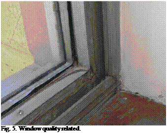 |
Poor insulation due to low quality windows. While the system sizing has been carried out for a particular number of windows with particular parameters, another, “real quality” parameter should have been taken into account as well. In the system design and sizing stage it was difficult or impossible to take into account the bad quality of the windows that have evident gaps (fig. 5).
Stratification effect due to the high ceiling (6.5 meters) of the Auditorium and almost laminated flow of the cooled air from the ducts on the ceiling placed over the windows did not allow the cold air to reach to the vitally important zone, where public is seated. The used ducting provided 8 outlets to the Auditorium, all above the second row of the shaded windows that face east-south (C on fig. 2.). We think that the shaded windows, in summers have been always so warm that most of the energy from the system has been spent on cooling down the air in the top half of the Auditorium, enormously decreasing the efficiency of the operation.
In order to address the situation, a much shorter and direct ducting from the DEC machine has been constructed (D on fig. 2.). This measure immediately positively effected the system operation. However soon the machine was stopped due to a problem related to filters (see below), thus no monitoring data is available illustrate the change.
3.1. Reliability
During the five years of operation three major malfunctions occurred.
The first one is related to the breakage of the gear transmission due to intense use of the heat recovery wheel during the first year of system operation. Since we have felt a need in a more efficient operation, we have enforced high rpms (around 40 cycles per minute) of the heat recovery wheel (HRW) rotation for very long times. Naturally this caused an accelerated wear out of one of the main gears of the HRW drive. The drive has been repaired, and a lower limit of HRW rotation has been set, along with modification of the control program to a less intense operation. In subsequent years no such a “casualty” has been recorded.
The second major problem has been relating to rather rare need in functioning of the three-way valves that switch the circuits of the water, both hot and cold. The rare rotation causes salts sedimentation from water on the friction surfaces of the valves that bring to unacceptably excessive tightness. Unfortunately, this phenomenon is only revealed by the malfunction of the valves. In this case too, the problem was addressed through a change in the control program, by enforcing all three-way-valves to rotate at least once a day, thus prevent the sedimentation.
The third major failure is related to ice formation in the main solar heat exchanger in wintertime. The reason was a very low atmospheric air temperature that has been transferred by the heat recovery wheel to the solar heat exchanger (in the exhaust channel). While in winter the solar heat exchanger was idle, however it was full of water and was frozen below water melting point causing fracture of the heat exchanger pipe-work. And again the problem was addressed through an appropriate change in the control algorithm of the machine operation, after which mentioned problem did not occur. Currently the control program stops the system operation if the temperature when the solar heat exchanger reaches 0°C, and signals about the need to empty the solar heat exchanger loop when the outdoor temperature reaches 6°C. It signals back to fill the aforementioned loop, when for the first time in a particular year the outdoor temperature reaches 24°C.
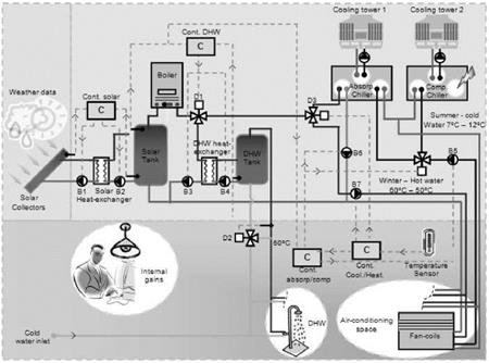 |
For the integrated solar system configuration, both heating and cooling options were considered. The most common solutions were adopted, with distribution of hot water or cold water to the load: use of solar collectors and a hot water storage tank, with a gas boiler backup, to provide hot water; the hot water is either directly used for space heating or used to drive an absorption water chiller. The hot or cold water is circulated through fan-coils located in the conditioned space — see Figure 1. The system may also provide domestic hot water (DHW). Another possibility considered, that may be interesting in larger buildings, corresponds to the use of an auxiliary vapor compression (electrical) machine, instead of an auxiliary gas boiler.
Fig. 1. Schematic of integrated solar heating and absorption cooling system for indoor space conditioning.
The solar collector types considered were flat-plate with selective coating (Junkers FKT-1s) and vacuum tube collector without concentrator reflector (Viessmann Vitosol 300).
Absorption chiller mechanical characteristics and costs vary according to building type (hot water applications). So, different thermal output ranges were used for the simulation of three different types of building: single-family house (lower range), and office building and hotel (medium
range). Table 2 present the parameters of thermal and electrical chillers and gas boiler used in the simulations.
|
Table 2. Parameters considered for Single-Effect (SE) and Double-Effect (DE) chillers and gas boiler.
|
The building configurations are shown in Table 3. For all building types, the same type of construction was considered.
|
Table 3. Parameters considered for the buildings type.
|
The consumption of DHW considered for the hotel was 1000 liters/day at 45°C in Winter and 1700 l/day at 45°C in the other seasons of the year. For the single-family house it was 200 l/day.
For the office building and hotel an air change rate of 1 ren/hour was considered, as well as an inside temperature between 20 and 25°C, with chilling water at 7°C. For the single-family house an air change rate of 0.5 ren/hour was considered, with an inside temperature between 20 and 25°C with chilling water at 15°C (no dehumidification).
F. Lucas1*, F. Boudehenn2, S. Amblard3, J. Castaing-Lavignotes4, M. Pons5,
N. Le Pierres, D. Stitou7, D. Mugnier8
1 Laboratoire de Physique du Batiment et des Systemes (LPBS) Universite de La Reunion.
2Commissariat a l’Energie Atomique — Institut National de l’Energie Solaire
3Centre Recherche et developpement CIAT
4Laboratoire de Thermique, Energetique et Procedes
5CNRS-LIMSI, BP 133, F-91403 Orsay Cedex, France
6Laboratoire optimisation de la conception et ingenierie de l’environnement — INES
7Laboratoire procedes, materiaux et energie solaire
8TECSOL SA
* Corresponding Author, lucas@univ-reunion. fr
Abstract
In recent years, the world market of air conditioning has been increasing very fast. To meet the occupant comfort demand, solar cooling processes offer an ecological promising alternative to conventional air conditioning process. Indeed, these technologies offer satisfactory comfort in building at a very low energy cost (Electrical consumption can be divided par ten to twenty). To allow a wide diffusion of these technologies it is necessary to reduce the installation cost and to guarantee optimal performances. For instance, the investment costs for solar cooling systems are far higher than classical systems investment. However, the running costs of the solar cooling processes are far lower than the classical ones; the cooling power cost is about ten times higher. By developing tools to help the sizing phase and the optimisation of the solar cooling systems, it will be possible to reduce the installation costs, to improve performance and thus overcome the major drawback for a broader use of this technology.
This paper describes a French research program proposing both an applied and fundamental study of solar cooling processes. Based on the contribution of eight industrial and scientific partners working within four pools, the project investigates the most promising solar cooling technologies as desiccant cooling process (pool 2), absorption cooling process (pool 3) and thermo-chemical cooling process (pool 4). Pool 1 focuses on the comparison and analysis of the three cooling processes covered by the other pools. Using the pool 1 results, pools 2, 3 and 4 propose a theoretical analysis to develop design tools based on modelling of cooling system components, cooling systems, control components and global cooling system coupled with buildings. An experimental survey is also carried out on five experimental facilities in order to perform an exhaustive validation procedure including also a sensitivity analysis and an inter-software comparison. At the end of the project, within 3 years, the partners will provide :
• A thermodynamic analysis of the solar cooling processes,
• Sizing tools suitable for preliminary studies,
• Optimized sizing tools.
Keywords: Solar cooling, energy saving, experimental survey, modeling, design tools, optimization, absorption process, desiccant process, thermo-chemical process.
Over the past fifteen years, the requirements of the building occupants have changed significantly. There is indeed an increasingly demand for rigorous comfort. The growth prospects of air conditioning markets are important for years to come. Indeed, the world market for air conditioning increased by about 4% per year. In a difficult energy and environmental background, it is urgent to propose bioclimatic passive solutions but also active techniques that can meet the requirements of comfort in buildings without overloading the electricity yield. The solar cooling systems represent this promising alternative to the conventional cooling systems using vapour compression. The state of the art of cooling technology using solar thermal energy to produce cold revealed two large families:
• Closed cycles: these systems produce cooled water by sorption for cooling or dehumidifying. In these systems, mechanical compression is replaced by a thermal compression. The existing systems on the market are absorption (sorption of the refrigerant on a liquid absorbent) or adsorption (sorption of refrigerant on a solid adsorbent) machines. These processes operate through a heat source, which temperature is generally between 60 and 110°C. Their coefficient of performance (COP) is around 0.5 to 0.7 (for single effect systems). These closed cycles represent the majority of existing solar cooling facilities, with a predominant share for absorption technology (60%). The thermochemical processes are also gas sorption systems following a closed cycle. Their principle is based on the use of a reversible chemical reaction between a solid reagent (as BaCl2 for solar applications) and a refrigerant gas (NH3). This process includes two distinct phases (reactive phases) and two intermediate transitional phases (pressurization and depressurization. The COP of the thermo-chemical systems varies from 0.3 to 0.5 in the basic versions.
•The open systems: In these systems, the air is directly treated (cooling, dehumidification) by contact with the refrigerant (water) and the desiccation components. These systems use for the drying either a rotating desiccant wheel (desiccant solid material) or a liquid desiccant bed. The temperature of the hot source necessary for the regeneration of desiccant materials is about 45 to 95°C. The COP of these systems varies between 0.5 and values greater than 1. Open systems are currently a relatively small part of existing facilities (about 10 to 15%), but represent a promising future for solar cooling.
The ORASOL project is intended to study and compare absorption, desiccant and thermochemical solar cooling systems. Six public laboratories and two private companies contribute to this work for a three years period.
This article proposes to define the objectives of the ORASOL project and to give a description of his organization. It will present the experimental facilities used and the expected results.
Olivier Marc1*, Franck Lucas1, Frantz Sinama1, Alain Bastide1, Eric Monceyron1, Francois
Garde1
1 LPBS. — Laboratoire de Physique du Batiment et des Systemes — Universite de La Reunion : IUT
Departement Genie Civil 97410 Saint Pierre — La Reunion — France
olivier. marc@univ-reunion. fr
Abstract
Solar cooling systems are unmistakably an interesting alternative to solve electric consumption problems of air conditioning systems working with mechanical vapour compression. The optimization program of solar cooling systems (ORASOL) managed by the national research agency (ANR) was created to propose a fundamental reflection, with the elaboration of simulation and sizing tools. Therefore the installation of several pilot — plants of various powers is necessary for the understanding and the development of this technology. For that, our laboratory the LPBS suggested setting up an experimental platform with a 30kW absorption chiller. This installation started at the beginning of March (summery period in Reunion Island) and throughout this document we present the first results. Furthermore we suggested carrying out a simulation tool which allows predicting the behaviour of both installation and the building, at any time step and without backup system. Firstly, we present a stage of simplified modelling of all the installation as well as experimental validation elements. The aim of this first phase is to estimate all components which require a detailed modelling.
Keywords: Solar cooling system, simulation, experimentation.
Search for thermal comfort in summer causes a significant increase in electricity consumption mainly due to the use of air conditioning systems working with mechanical vapor compression. Solar cooling systems operating with absorption chillers are an interesting alternative to meet satisfactory comfort inside buildings using little electrical energy. The main energy source is the solar energy and there is an almost perfect phasing between the cooling need and the solar resource. Our project takes part of ORASOL program which aim is to propose both fundamental and applied reflections for solar cooling systems in order to improve comfort conditions in buildings. The first part of this article presents our installation and the first results. Secondly, we will present a simplified model, developed for the complete study of a solar cooling system operating with absorption chiller. Finally we will propose a comparison between the simulation results and data from out experimental platform.