Как выбрать гостиницу для кошек
14 декабря, 2021
 |
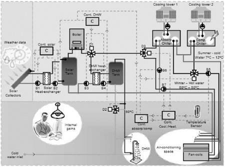
For the integrated solar system configuration, both heating and cooling options were considered. The most common solutions were adopted, with distribution of hot water or cold water to the load: use of solar collectors and a hot water storage tank, with a gas boiler backup, to provide hot water; the hot water is either directly used for space heating or used to drive an absorption water chiller. The hot or cold water is circulated through fan-coils located in the conditioned space — see Figure 1. The system may also provide domestic hot water (DHW). Another possibility considered, that may be interesting in larger buildings, corresponds to the use of an auxiliary vapor compression (electrical) machine, instead of an auxiliary gas boiler.
Fig. 1. Schematic of integrated solar heating and absorption cooling system for indoor space conditioning.
The solar collector types considered were flat-plate with selective coating (Junkers FKT-1s) and vacuum tube collector without concentrator reflector (Viessmann Vitosol 300).
Absorption chiller mechanical characteristics and costs vary according to building type (hot water applications). So, different thermal output ranges were used for the simulation of three different types of building: single-family house (lower range), and office building and hotel (medium
range). Table 2 present the parameters of thermal and electrical chillers and gas boiler used in the simulations.
|
Table 2. Parameters considered for Single-Effect (SE) and Double-Effect (DE) chillers and gas boiler.
|
The building configurations are shown in Table 3. For all building types, the same type of construction was considered.
|
Table 3. Parameters considered for the buildings type.
|
The consumption of DHW considered for the hotel was 1000 liters/day at 45°C in Winter and 1700 l/day at 45°C in the other seasons of the year. For the single-family house it was 200 l/day.
For the office building and hotel an air change rate of 1 ren/hour was considered, as well as an inside temperature between 20 and 25°C, with chilling water at 7°C. For the single-family house an air change rate of 0.5 ren/hour was considered, with an inside temperature between 20 and 25°C with chilling water at 15°C (no dehumidification).