Как выбрать гостиницу для кошек
14 декабря, 2021
Usually, three groups of fluids are distinguished: dry (positive slope), isentropic (zero slope) and wet (negative slope) fluids. For low temperature organic Rankine cycle systems and particularly with low power output levels, wet fluids like water, methanol or ethanol are not suitable. This category of fluids requires a superheat in order to avoid moisture after the expansion process. Fortunately, there are dry and isentropic fluids that do not exhibit excessive moisture after the expansion of the vapor through the expansion device. When isentropic fluids are used, isentropic expansions of saturated organic vapors result in saturated or superheated vapor regions so that erosion of the blades is avoided. Dry fluids with high positive slopes yield low efficiencies. In order to overcome this drawback, a regenerative heat exchanger should be used in parallel with the evaporator and condenser to raise the temperature of the liquid entering the evaporator. An ideal working fluid for ORCs is likely to have a vertical vapor saturated line and a vertical liquid saturated line so that all the heat input transfer should take place during the phase change and the heat rejection at the condenser occurs at the minimum temperature [1, 2, 6]. Fig.1 shows the T-s diagram for an ideal working fluid.
ik
![]()
T [K] [15]
s [kJ/kg. K]
Fig. 1: T-s diagram for the ideal working fluid
|
Substance |
Physical data |
Safety data |
Environmental data |
|||||
|
Molecular Mass (kg/kmol) |
a T 1bp (°C) |
b t crit (°C) |
cP crit (MPa) |
ASHRAE 34 safety group |
Atmospheric life time (yr) |
dODP |
eGWP (100 yr) |
|
|
RC318 |
200.03 |
-6.0 |
115.2 |
2.778 |
A1 |
3200 |
0 |
10250 |
|
R600a |
58.12 |
-11.7 |
135 |
3.647 |
A3 |
0.019 |
0 |
~20 |
|
R114 |
170.92 |
3.6 |
145.7 |
3.289 |
A1 |
300 |
1.000 |
10040 |
|
R600 |
58.12 |
-0.5 |
152 |
3.796 |
A3 |
0.018 |
0 |
~20 |
|
R601 |
72.15 |
36.1 |
196.5 |
3.364 |
— |
0.01 |
0 |
~20 |
|
R113 |
187.38 |
47.6 |
214.1 |
3.439 |
A1 |
85 |
1.000 |
6130 |
|
Cyclohexane |
84.16 |
80.7 |
280.5 |
4.075 |
A3 |
n. a |
n. a |
n. a |
|
R290 |
44.10 |
-42.1 |
96.68 |
4.247 |
A3 |
0.041 |
0 |
~20 |
|
R407C |
86.20 |
-43.6 |
86.79 |
4.597 |
A1 |
n. a |
0 |
1800 |
|
R32 |
52.02 |
-51.7 |
78.11 |
5.784 |
A2 |
4.9 |
0 |
675 |
|
R500 |
99.30 |
-33.6 |
105.5 |
4.455 |
A1 |
n. a |
0.738 |
8100 |
|
R152a |
66.05 |
-24.0 |
113.3 |
4.520 |
A2 |
1.4 |
0 |
124 |
|
R717 (Ammonia) |
17.03 |
-33.3 |
132.3 |
11.333 |
B2 |
0.01 |
0 |
<1 |
|
Ethanol |
46.07 |
78.4 |
240.8 |
6.148 |
n. a |
n. a |
n. a |
n. a |
|
Methanol |
32.04 |
64.4 |
240.2 |
8.104 |
n. a |
n. a |
n. a |
n. a |
|
R718 (Water) |
10.2 |
100 |
374 |
22.064 |
A1 |
n. a |
0 |
<1 |
|
R134a |
102.03 |
-26.1 |
101 |
4.059 |
A1 |
14.0 |
0 |
1430 |
|
R12 |
120.91 |
-29.8 |
112 |
4.114 |
A1 |
100 |
1.000 |
10890 |
|
R123 |
152.93 |
27.8 |
183.7 |
3.668 |
B1 |
1.3 |
0.020 |
77 |
|
R141b |
116.95 |
32.0 |
204.2 |
4.249 |
n. a |
9.3 |
0.120 |
725 |
|
R245fa |
134.05 |
15.3 |
154.1 |
3.64 |
B1 |
8.8 |
0 |
820 |
|
R236fa |
152.0 |
-1.4 |
124.0 |
3.20 |
— |
209 |
0 |
6300 |
|
R227ea |
170.0 |
-17.5 |
102.0 |
2.95 |
— |
36.5 |
0 |
2900 |
|
a Tbp : Normal boiling point; b Tcrit: Critical temperature; c Pcrit: Critical pressure; |
|
1 2 3 4 5 6 7 8 9 10 11 12 13 14 15 16 17 18 19 20 21 22 23 |
dODP: Ozone depletion potential, relative to R-11; eGWP: Global warming potential, relative to CO2. n. a: non available
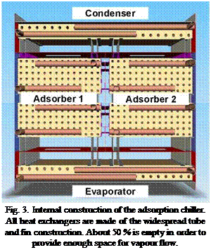 |
One of the major problems of the construction of adsorption chillers is the need to design a vacuum vessel containing the adsorber heat exchangers, the evaporator and the condenser. Typical design rules for vacuum vessels result in very heavy and voluminous constructions due to the demands of stability against atmospheric pressure. In order to overcome this disadvantage we developed a design, where the heat exchangers and the internal construction of the machine are used as a support for the vacuum-tight envelope. This dual-use allows to applying thin stainless steel metal sheet as vacuum containment (See fig.3). This light and very simple construction results in very high savings of material and volume and is a major step for the construction of an economical adsorption chiller.
Due to the alternating batch process the operation of the two sorptive heat exchangers is characterized by their transient behaviour. Therefore, a dynamic model of the sorptive heat exchanger was developed applying the modelling language Modelica and using the simulation environment Dymola. The dynamic model of the sorptive heat exchanger is using the Modelica Standard Library (version
2.2.2. ) in combination with the Modelica_Fluid (Beta version) library which is the commonly used library for thermofluid modelling in Modelica at Fraunhofer ISE. For the description of the moist air properties the Modelica. Media. MoistAir model was applied.
The two-dimensional numerical model is based on the following assumptions and simplifications:
• Modelling of one pair of adsorption and cooling channels
• Lumped, constant heat and mass transfer coefficients for adsorption and evaporation processes • No heat transfer and thus no heat losses to the surrounding
The sorptive heat exchanger model may be discretized in a desired number of volume elements. Each element comprises an adsorption channel model, a cooling channel model as well as a model of the heat exchanger wall.
Adsorption channel model
Both the adsorption and cooling channel models are based on finite volume elements. Applying the Modelica_Fluid standardized connectors, volume elements may be connected by fluid ports in which the medium variables of state pressure and enthalpy, the medium mass flow rate and in case of multisubstance media such as moist air the component mass fraction are handed over.
The sorption material and therefore the physical description of the sorption process is included in the adsorption channel model. The driving force of the adsorption process is the pressure difference between the partial pressure of vapour in the air volume pv and the equilibrium pressure of the sorption material pequ. The sorption process is mathematically described by the following linear interrelation:
in which flsorp (in the order of 10-8 kg/Ns) is the global mass transfer coefficient describing the
kinetics of water uptake by the sorption material. In order to solve the equation the equilibrium pressure pequ must be determined from the sorption equilibria. To this purpose a generalized form of Dubinin’s theory of volume filling is applied and implemented in a sorption material package for the use in Modelica [2]. The interaction between the sorption material and the air volume is described by postulating the balance equations of mass and energy via a set of differential equations. In the adsorption channel model the heat of adsorption is released in the sorption material, raising its temperature. Cooling of the sorption material is then calculated by convective heat transfer to the process air bulk flow and via conduction through the separating heat exchanger wall. To this purpose, the heat exchanger wall and the adsorption model volume element are connected via a heat port in which the state variable temperature and the flow variable heat flow rate are handed over.
Heat exchanger wall model
The heat exchanger wall model is a predefined Modelica model including the thermal mass of the aluminium wall and the heat conduction through the wall. It is connected to the cooling channel and the adsorption channel models via heat ports.
Cooling channel model
![]()
The cooling channel model is structurally similar to the adsorption channel model. The evaporation model again follows a linear driving force approach:
The cooling channel wall is always covered by a thin water film from which water evaporates into the air flow. Water is introduced to the volume element at a constant temperature and assumed to instantaneously reach the surface temperature which is a valid assumption for a thin water film [3]. Knowing the evaporation rate determined by equation 2 and taking account of the convective heat transfer rate between the cooling channel air flow and the heat exchanger wall, the balance equations of heat and mass conservation are solved.
The reactive bed is compacted in the reactor between the gas diffuser which is, in that case, fixed by rigid wedges, and the heat exchanger wall. A controlled pressure is applied to the coolant and therefore under the heat exchanger wall. During reaction, the coolant level and the displacement sensor give information on the relative position of the wall.
The reactions can occur after compacting. Thermodynamic constraints were fixed, i. e. the heat exchanger and evaporator/condenser temperatures were chosen according to thermodynamic equilibrium of solid/gas reaction and liquid/gas reaction [1].
The overall reaction advancement X is the number of mole of hexahydrated salt (which is deduced from the level in the liquid reacting water tank) divided by the total number of salt moles in the block. X is time dependant, and it is include between 0 and 1.
To simplify the identification of heat and mass transfer parameters, some constraints were applied:
• Temperature and pressure are fixed in the stability domain of the reactive salt i. e. at the boundaries of the reaction (X = 0 and X = 1).
• Transfers are assumed 1D because of the small ratio thickness / diameter of the sample, from 10 to 50 mm / 300 mm. Moreover, the external boundary is thermally insulated and airtight.
The measurements from the heating wire, thermocouples in the reactive bed and fluxmeter were used to identify the effective thermal conductivity. This identification uses the Fourier’s law in steady state.
Owing to the range of particle size and working pressure, the diffusion through the porous media is controlled by Darcy’s law. Nevertheless, the Knudsen diffusion could be envisaged. There are 3 categories of flow according to the mean free path of the fluid through the pores of the porous media.
In our case, the mean free path is close to the mean diameter of pores. The convective flow and the diffusive flow are not negligible because of Darcy’s law and Knudsen’s law respectively, equation 2.
![]() к dp Dk dp p dz p dz
к dp Dk dp p dz p dz
The Darcy’s law is modified by the introduction of the Klinkenberg’s coefficient b which depends on the Knudsen diffusivity Dk, the dynamic viscosity g, and the permeability k. The pressure evolution through the reactive porous media is given by this equation combined with the mass balance equation, equation 3. A numerical solution has been implemented using the commercial software: COMSOL®.
The determination of the permeability and the Klinkenberg’s coefficient was carried out in transient state. First, the gas tank volume and the gas volume above the reactive block are disconnected. Each of them is filled by steam up to the pressure pg and pd, respectively for the gas storage tank and the dead volume in the reactive bed. Then, the two volumes are connected together. The experimental evolution of the two pressures versus time is compared with the simulated one. The permeability and the Klinkenberg’s coefficients are determined by these pressure evolutions. Each volume pressure is simulated according to equation 3. The typical simulations are presented in figure 3. The first equalization of pressure Peg characterizes the gas tank volume and the dead volume above the reactive bed. As this pressure equalization occurs in less than 1 ms, we assume that it does not involve the porous volume of the reactive bed. After this first step, the gas diffuses through the porous volume of the reactive bed, and the pressure evolves from (peg, teg) to (pec, tec). The identification of k and b is carried out between these two points.
|
![]()
Pg
![]() teg< 1 ms
teg< 1 ms
Figure 3 : Typical evolution of pressure versus time in transient state
American University of Armenia (AUA), Engineering Research Center (ERC), 40 Marshall Baghramian,
Yerevan 0019, Armenia
Corresponding Author, arthambr@aua. am
Being one of the early ones in the world, this is the first solar driven desiccant cooling system in Armenia and NIS. The article discusses issues related with the operation of the system since its commencement in February 2002. Topics involve: A. Efficiency issues, covering influence of the perception of humidity, quality of the windows of the space cooled, monitoring results; B. Reliability, including malfunctions related to heat recovery wheel drive, fluid (antifreeze) circulation, overheating, sediment formation on three-way valves; solar heat exchanger breakage due to ice formation; C. other operational issues: PV system integration; filters problem.
Keywords: solar hot water, solar driven cooling, desiccant cooling, solar PV.
“Design And Installation of a Solar Driven Desiccant Cooling Demonstration System” (DESODEC) project funded by INCO Copernicus Program of the EU involved more than three years of collaborative work of five partners: the DER/INETI (Portugal), ISE/Fraunhofer (Germany), InterSolarCenter (Russia), Contact-A and Engineering Research Center of the American University of Armenia. As a result, with the energy provided by the Solar Water Heating (SWH) collector field installed on the rooftop of the AUA building and operation of the Desiccant Evaporative Cooling (DEC) machine, heating and cooling capability is achieved in a 154 seats auditorium of AUA.
In this article we summarize 6 years experience of the operation of the DESODEC system.
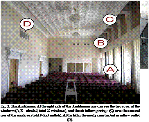
The solar field, fig. 1 consists of 32 flat plate hot water collectors with total surface area of 64 m2 providing up to 40 kW of power equivalent. The solar field and the panels are designed by DER/INETI together with Contact-A and manufactured by SolarEn LLC company in Armenia. Desiccant cooling machine comprising desiccant wheel, heat recovery wheel, humidifiers, fans and control and monitoring devices are designed by ISE/Fraunhofer and manufactured mostly in the USA and Germany. The system can deliver up to 8000 m3 cooled air with cooling power equal to 60 kW in the desiccant cooling mode to the Auditorium (fig. 2) [1-4].
The system has a 3 ton stratified storage tank designed to provide a heat buffer and a temperature difference for efficient thermodynamic cycle.
 |
Figures 2. a. and b. describe the solar driven desiccant cooling well-known operating principle employed: air that is pre-desiccated by the desiccant absorption (evaporative cooling) wheel is cooled by humidifiers. The cooling efficiency of humidifiers is considerably elevated due to the air desiccation. Solar energy is used for regeneration of the desiccant absorption wheel. To increase the efficiency of the process, a heat recovery wheel is used to return useful energy (cold or warmth) from the exhaust channel.
|
|
|
Fig. 3. a. Components of the DEC machine; b. Temperature-humidity diagram of the system operation. |
Thus, in this system, a cooling or heating function is performed by a solar driven machine, that uses up to 40kWheat low potential solar energy provided by solar hot water panels, and an average of 5kWelectric, for driving the balance of the system.
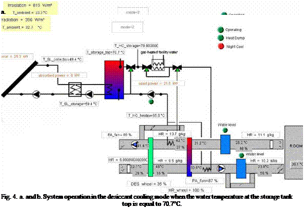
Figures 4. A. and b. show the screenshots of the system controls interface that have comprehensive information on the operation. One can see that water temperature of 94°C is required to output 16.6°C air with relative humidity equal to 52%, and at 70.7°C yields 23.8°C and 56% respectively.
b.
The house has two storeys with a total floor area of 213 m2 and has well insulated reverse brick veneer external walls. The windows of the house are double glazed 4 mm clear with 12 mm argon filled and low E film. It has solid construction external doors.
 |
Figures 2 — 4 show monthly profiles of cooling, space heating and domestic water heating loads for the house exposed to Adelaide, Brisbane and Sydney typical year weather data.
|
Fig. 3. Monthly cooling, DHW and SH load profiles — BRISBANE |
|
Fig. 4. Monthly cooling, DHW and SH load profiles — SYDNEY |
Monthly cooling and space heating loads for the house were calculated using AccuRate package [9]. The house exposure to different weather data results in 6.9, 7.7, and 7.6 star ratings of the house in Adelaide, Brisbane and Sydney. The star rating is a measure of energy performance of the house based on the fabric and form, not including the effect of the cooling / heating system used in the house. This rating system is mandatory for new Australian houses.
Adelaide is a semi arid region with low humidity, mild winter and hot summer. Brisbane is warmer with relatively high humidity, mild summer and short heating period. Sydney is cooler and less humid and has a slightly longer heating season than Brisbane. These are clearly illustrated in Figs. 2 — 4 above and Fig. 5 which shows the montly latent load as a percentage of the total load.
|
|
J FVIAMJ J ASOND Fig. 5. Latent load as a percentage of total cooling loads
The monthly figures for DHW loads were derived from Australian Standard 4234 [10] for a medium size system which provides seasonal (monthly) load profile, hourly load profile and monthly cold water temperatures. Monthly space heating (SH) and cooling loads were estimated using an Australian building energy rating software, AccuRate.
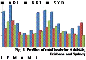
Monthly profile total loads are shown in Fig. 6. As seen, Adelaide monthly total loads are much higher than Brisbane and Sydney loads which are very similar. As expected, monthly loads peak in peak summer and winter months and level during spring and autumn.
 4000
4000
І 3000
о"
<
З 2000
<
I—
£ 1000
о
For the analysis, the main metrics used to illustrate the system performance are the solar fraction (SF) and total useful heat. Solar fraction is defined as the fraction of solar energy used to satisfy the load. The load not met by solar energy is handled by an auxiliary system.
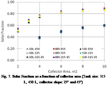 |
Figure 7 shows the solar fractions as functions of collector area for systems serving houses in the three cities. Two hot water tank sizes (315 L and 450 L) were studied; the collector were tilted at 25° and 45 °C.
As shown, for Brisbane and Sydney, a collector area of 6 m2 can provide more than 80% of the heat required for cooling, heating and hot water. On the other hand, for Adelaide, much lower solar fractions are delivered by the same system size without much improvement in the solar fraction when a larger collector area is used. Two other interesting findings revealed by Fig. 7 are: (1) a tank size of 315 L performs as well as 450 L tank, and (2) collector slope between 25 — 45 is insensitive to system performance.
Fig. 7 shows clearly that for Brisbane and Sydney, application of an integrated thermal system is appropriate. On the other hand, due to drier climate (Fig. 5), the application of such a system in Adelaide is not leading to large energy savings.
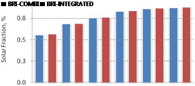 |
Futher analysis shows that thermal performance of an integrated thermal system is as good as the combisystem performance (heating and hot water only) in terms of solar contribution to handle the total load (Figs. 8 — 9).
2 3 4 6 8 10
Collector Area, m2
Fig. 8. Solar Fraction for Combisystem (heating and hot
water only) and Integrated System — Brisbane
4 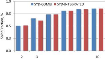 6 8
6 8
Collector Area, m2
Fig. 9. Solar Fraction for Combisystem (heating and hot
water only) and Integrated System — Sydney
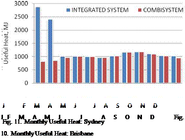 |
The system performance can also be measured in terms of monthly useful energy delivered by the system to satisfy the loads. This is illustrated in Figs. 10 — 11 which compare the useful heat delivered by an integrated thermal system and a combisystem with a 6 m2 collector area installed in Brisbane and Sydeny. As shown, the integrated system delivers much higher useful energy than the combisystem, particularly during the summer months. For a collector area of 6 m2 and a 315 L storage tank, the annual useful heat delivered by the intgerated system for Brisbane and Sydney are 17.0 GJ and 11.6 GJ, respecticely, compared to 15.7 GJ and 11.9 GJ delivered by the combisystems.
An analysis of the thermal performance of an integrated heating system for the provision of hot water, space heating, cooling and dehumidification has been presented. It was observed from numerical investigation that for a location like Adelaide with semi arid climate, such a system will work with a minimum role for the solar liquid desiccant cooling sub-system. In such a case, a combisystem or the use of an absorption cooling system is more suitable. On the other hand, for locations such as Sydney and Brisbane, such systems are appropriate. An integrated thermal system with a 315 L tank, and a 6 m2 evacuated tube collector area can serve typical house in either Brisbane or Sydney.
[1] Australian Greenhouse Office, Australian Residential Building Sector — Greenhouse Gas Emissions 1990 — 2010 — Executive Summary Report, 1999.
[2] Lee, T., Ferrari, D., Donnelly, E. (2003): Active Solar Space Heating for a Cool Temperate Climate: A Case Study, 41st ANZES Solar Energy Society Conference, Melbourne.
[3] Saman W. Y. and Mudge, L. 2002, Development, implementation and promotion of a scoresheet for household greenhouse gas reduction in South Australia, Australian Greenhouse Office.
[4] Henning, H.-M. (2004): Solar Air-Conditioning of Buildings, EuroSun2004, Freiburg, Germany, 24.26.6.04.
[5] Krause, M., Saman, W. Y. Vajen, K. (2005), Regenerator Design for Open Cycle Liquid Desiccant Systems — Theoretical and Experimental Investigations, International Conference on Solar Air Conditioning, Staffelstein, Germany, 6.-7.10.2005.
[6] Krause M., Saman W. and Vajen K. (2006): Optimisation of a regenerator for open cycle liquid desiccant air conditioning systems, Proc. 2006 Eurosun Conference, Glasgow, Scotland.
[7] TRNSYS 16 Reference Manual, 2004.
[8] Halawa, E., Bruno, F., Saman, W. (2007): Potential Application of Combisystem for An Australian Climatic Region, ISES Solar World Congress 2007, Beijing, September.
[9] Hearne Website — http://www. hearne. co. nz/ — Residential Building Thermal Performance Assessment (2006) — viewed 20 June 2007.
[10] Australian Standard AS 4234-1994: Solar Water Heaters — Domestic and Heat Pump — Calculations of Energy Consumption.
Figure 3 shows a scheme of the new developed control strategy. In this case, driving temperature can rise as high as the chiller control allows. Thus, high irradiation can be used and no driving energy or exergy is wasted. Cooling water temperature is not kept constant anymore but it is used as a control parameter. Base of the control strategy is the method of the characteristic equation — a simple model which yields the cooling capacity of an absorption chiller as function of the so-called characteristic temperature function AAt, a function of the temperatures of the external water circuits (hot, cooling, chilled water). According to this equation, cooling capacity does not change, if the characteristic temperature function remains constant. From the characteristic temperature function follows immediately how changes of one external temperature can be compensated by control of the other external temperatures. That means for example a higher driving temperature can be compensated by increasing the cooling temperature without a change in the chilled water temperature.
In [2] the method of the characteristic equation was presented. The adapted characteristic equation for the 10 kW absorption chiller is Q E = 0,42 • AAt + 0,9 with the adapted characteristic temperature function AAt’ = tG — 2.5 • tAC +1.8 • tE . Temperatures tG, tA, tC, tE are the arithmetic mean values of inlet and outlet of the external water loops at generator, absorber, condenser and evaporator, tAC is the arithmetic mean value of tA and tC. Solving of AAt’ for the cooling water inlet
chilled water outlet temperature tEout is required, QE is substituted by VE • p • cp • (Ein — tEout) and tEout is set to the required value, e. g. 15°C if a chilled ceiling is applied. The measured values of the other temperatures and the chilled water flow rate are continuously inserted and tAin recalculated hereupon. I. e., the characteristic equation model defines the necessary cooling water temperature. A standard PID-controller in a closed loop is used to control the fan frequency to provide this temperature. Via a frequency converter the speed of the cooling tower fan is set according to the output of the controller.
Summing up, this control strategy can manage unsteady driving temperatures. The cooling water inlet temperature is adapted to hold chilled water temperature constant. First successful laboratory tests of this control are presented in [8]. This paper focuses on comparison of the two control strategies by simulation.
The solar thermal cooling facility installed at Universidad Carlos III de Madrid (UC3M) was first configured to operate with 50 m2 solar thermal collectors array in the primary loop and a 2 m3 Thermal Energy Storage (TES) in the secondary loop in order to store and supply hot water as energy input to run the water fired absorption chiller. A complete description of the facility can be found in [4]. But from a recent optimization work done over the facility with the help of the TRNSYS simulation program, it was concluded that working with a lower TES capacity of 0.1 m3, the daily and seasonal values of COP and SCOP improves from the previous configuration [5]. Even with no TES at all the COP and SCOP increased, pointing out that the design and sizing of the TES in domestic application is of great importance.
In June of 2008 the facility was modified to work with no storage, bypassing the 2 m3 TES and supplying the hot water coming from the solar thermal collectors directly to the absorption chiller by means of a heat exchanger, see Figure 1. Hot water enters the generator of the absorption chiller earlier than working with TES and achieving higher generator temperatures. This makes the solar facility to start the cold production earlier and with higher cooling rates, but demanding a higher rejection rate to the ambient as well.
1.1. Experimental results
Experimental results for July 9, 2008 are presented in Figures 2, 3 and 4. This day is selected as representative of the season. The absorption chiller installed in the UC3M’s solar cooling facility is a Yazaki pumpless WFC-10 of 35 kW nominal cooling capacity. It incorporates a solution control to work under part load when driven by solar energy.
|
Figure 1. Current configuration of the experimental solar cooling facility at Universidad Carlos III de Madrid. SC: Solar Collectors, HX: Heat eXchanger, AC: Absorption Chiller, FC: Fan-Coil, WTC: Wet Cooling Tower. Numbers in the Figure refers to the facility loops. |
In Figure 2 it is shown the behaviour of the solution control marked by circles. This behaviour is more noticeable when high inlet temperatures to the generator are achieved in a relatively short period of time, which is the case of the current facility configuration. The solution control provokes a sudden drop in the cooling rate of the absorption chiller, making the daily COP and SCOP to suffer the same sudden drop as it is shown in Figures 3 and 4. Nevertheless this occurs for a relatively short period of time too. Current operating conditions of the solar cooling facility are presented in Table 1.
|
Relevant temperatures for July 9, 2008.
Figure 2. Relevant temperatures of the experimental solar cooling facility, July 9, 2008. Circles in the figure show the behaviour induced by solution control of the absorption chiller. |
|
Table 1. Current operating conditions for UC3M solar cooling facility.
|
The parameters presented in Figure 3 have been obtained by means of energy balances in the cooling tower, generator and evaporator loops. The total incident radiation rate has been calculated as the product of the incident radiation on the tilted surface and the total collector area.
|
oooooooooooooooooooooooo о о о о о о о о о о о о о о о о о о о о о о о о О V-‘ (Si СО Sr ю СО |Si СО О) О V-‘ (Si со Sr ю (id |Si СО СТ» О т — (Si со л-л-л-л-л-л-л-л-л-л-СЧСЧСЧСЧ Time [h] |
Figure 3. Experimental instantaneous cooling rate, heat input to generator, heat rejected in cooling tower and
incident radiation energy for the solar cooling facility, July 9, 2008. Circles in the figure show the behaviour
induced by the solution control of the absorption chiller.
|
|||||||||||||||
 |
|||||||||||||||
|
|||||||||||||||
|
|||||||||||||||
|
|||||||||||||||
|
|||||||||||||||
|
Instantaneous COP and SCOP for July 9, 2008.

 0,9
0,9
0,8
0,7
0,6
0,5
0,4
0,3
0,2 0 1
Figure 4. Instantaneous COP and SCOP for the solar cooling facility, July 9, 2008. Circle in the figure show the
behaviour induced by the solution control of the absorption chiller.
1.2. Recooling loop
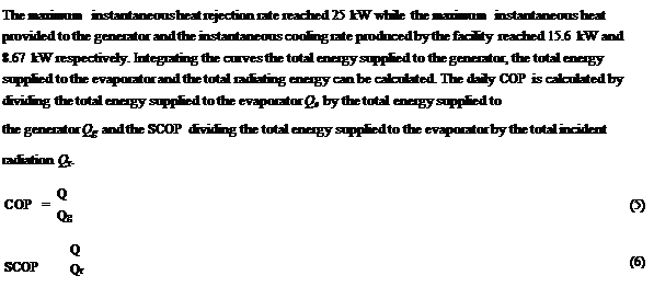
The recooling loop of the absorption chiller incorporates a temperature control and a solenoid valve in order to permit the flow of cooling water when the condensation temperature rises above 30 °С. This is convenient in order to keep the value of the thermal inertia of the absorption chiller low and to begin the cold production earlier in the morning. This provokes a temperature difference from the inlet and outlet of the recooling loop to stay almost constant during the operation of the absorption chiller in the range of 7-9 °С. The necessities of instantaneous heat rejection will then fluctuate between maximum values of 24-30 kW using a wet cooling tower in current operating conditions and favourable weather conditions (rel. humidity between 10 and 40 %).
To simulate the selected collectors, type 536 from the TESS library was used. This type is based on the theoretical equations developed in[3], see also[4]. This model basically follows the equation:

 -—(t — T )
![]() CR in amb /
CR in amb /
With R1 and R2 as modifiers for flow correction different from the tested flow rate, Nparallel as the number of collectors in parallel, F1 and F2 as the intercept and slope of the collector efficiency curve and CR as the concentration ratio of the trough. Since the collector had physically parallel rows which where connected hydraulically in series, Nparallel was set to 1. The one-dimensional IAM-values as well as both F1 and F2 (0,76 and 4,17) where calculated from data provided by the manufacturer. The concentration ratio of the RMT is 7.165 (ratio of the net aperture area to the receiver area). By using an equation to reduce the incident beam radiation, the possible effect of soiling of the coated polished aluminium reflector caused by the exhaust of the nearby chimneys was taken into account. The shading of parallel rows was simulated with a shading mask (type 30) of the TRNSYS standard component library, for precise description see[5].
4.2 Absorption chiller
The absorption chiller is a derivation of Robur model ACF 60 LB, which is a single stage — gas fired — air cooled (dry fans) — aqua ammonia absorption chiller for low temperature brine generation. The chiller was adapted to cope with solar heat by replacing the gas burner with a heat exchanger wrapped around the generator. Chillers’ main technical specifications and performance figures are reported in Tablel and Figures 4 and 5 respectively.
Antoine Dalibard*, Dirk Pietruschka, Ursula Eicker, Jhrgen Schumacher
zafh. net — Centre of Applied Research Sustainable Energy Technologies
University of Applied Sciences Stuttgart, Schellingstr.24, 70174 Stuttgart,
*antoine. dalibard@hft-stuttgart. de, Tel +49 711 8926 2875, Fax +49 711 8926 2698
Abstract
The paper deals with the dynamic simulation of a large solar adsorption cooling plant, located in the headquarters of the company FESTO (Southern Germany). This installation consists of 1218 m2 of vacuum tubes collectors of the type CPC and three adsorption chillers with a total nominal cooling capacity of 1.05 MW. A detailed dynamic simulation model of the solar plant and the adsorption chillers has been developed in order to predict the performance of the system. The dynamic behaviour of both the solar plant and the adsorption chillers were simulated for different operating conditions and compared with measurement data. The simulation results show a good agreement with the measurements. The model thus validated will be used for further investigations and to perform online simulation for an automated alarm and fault detection system.
Keywords: solar, cooling, adsorption, dynamic, simulation.
1. Introduction
1.1. Technology Centre of FESTO AG (Berkheim/Esslingen)
The innovative and highly energy efficient office building of the FESTO AG & Co. KG in Esslingen, with a useful floor area of 26.000 m2 is cooled in summer by three 350 kW adsorption chillers (manufacturer: Mayekawa) and additionally through thermally activated bore piles of the buildings foundation. The cooling energy of the bore piles is provided to the thermally activated concrete ceilings of the building and the cooling energy of the adsorption chillers is mainly used to cool the air in the ventilations systems of the building. Since the completion of the building in 2001, the driving heat for the chillers was provided by gas boilers and waste heat from the production facility. Since the end of 2007, a large solar plant, consisting of 1218 m2 vacuum-tube collectors of the type CPC Star Azurro from the manufacturer Paradigma, contribute to heat production for cooling and heating.