Как выбрать гостиницу для кошек
14 декабря, 2021
The solar thermal cooling facility installed at Universidad Carlos III de Madrid (UC3M) was first configured to operate with 50 m2 solar thermal collectors array in the primary loop and a 2 m3 Thermal Energy Storage (TES) in the secondary loop in order to store and supply hot water as energy input to run the water fired absorption chiller. A complete description of the facility can be found in [4]. But from a recent optimization work done over the facility with the help of the TRNSYS simulation program, it was concluded that working with a lower TES capacity of 0.1 m3, the daily and seasonal values of COP and SCOP improves from the previous configuration [5]. Even with no TES at all the COP and SCOP increased, pointing out that the design and sizing of the TES in domestic application is of great importance.
In June of 2008 the facility was modified to work with no storage, bypassing the 2 m3 TES and supplying the hot water coming from the solar thermal collectors directly to the absorption chiller by means of a heat exchanger, see Figure 1. Hot water enters the generator of the absorption chiller earlier than working with TES and achieving higher generator temperatures. This makes the solar facility to start the cold production earlier and with higher cooling rates, but demanding a higher rejection rate to the ambient as well.
1.1. Experimental results
Experimental results for July 9, 2008 are presented in Figures 2, 3 and 4. This day is selected as representative of the season. The absorption chiller installed in the UC3M’s solar cooling facility is a Yazaki pumpless WFC-10 of 35 kW nominal cooling capacity. It incorporates a solution control to work under part load when driven by solar energy.
|
Figure 1. Current configuration of the experimental solar cooling facility at Universidad Carlos III de Madrid. SC: Solar Collectors, HX: Heat eXchanger, AC: Absorption Chiller, FC: Fan-Coil, WTC: Wet Cooling Tower. Numbers in the Figure refers to the facility loops. |
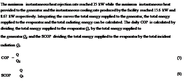
In Figure 2 it is shown the behaviour of the solution control marked by circles. This behaviour is more noticeable when high inlet temperatures to the generator are achieved in a relatively short period of time, which is the case of the current facility configuration. The solution control provokes a sudden drop in the cooling rate of the absorption chiller, making the daily COP and SCOP to suffer the same sudden drop as it is shown in Figures 3 and 4. Nevertheless this occurs for a relatively short period of time too. Current operating conditions of the solar cooling facility are presented in Table 1.
|
Relevant temperatures for July 9, 2008.
Figure 2. Relevant temperatures of the experimental solar cooling facility, July 9, 2008. Circles in the figure show the behaviour induced by solution control of the absorption chiller. |
|
Table 1. Current operating conditions for UC3M solar cooling facility.
|
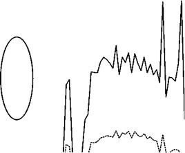
The parameters presented in Figure 3 have been obtained by means of energy balances in the cooling tower, generator and evaporator loops. The total incident radiation rate has been calculated as the product of the incident radiation on the tilted surface and the total collector area.
|
oooooooooooooooooooooooo о о о о о о о о о о о о о о о о о о о о о о о о О V-‘ (Si СО Sr ю СО |Si СО О) О V-‘ (Si со Sr ю (id |Si СО СТ» О т — (Si со л-л-л-л-л-л-л-л-л-л-СЧСЧСЧСЧ Time [h] |
Figure 3. Experimental instantaneous cooling rate, heat input to generator, heat rejected in cooling tower and
incident radiation energy for the solar cooling facility, July 9, 2008. Circles in the figure show the behaviour
induced by the solution control of the absorption chiller.
|
|||||||||||||||
 |
|||||||||||||||
|
|||||||||||||||
|
|||||||||||||||
|
|||||||||||||||
|
|||||||||||||||
|
Instantaneous COP and SCOP for July 9, 2008.

 0,9
0,9
0,8
0,7
0,6
0,5
0,4
0,3
0,2 0 1
Figure 4. Instantaneous COP and SCOP for the solar cooling facility, July 9, 2008. Circle in the figure show the
behaviour induced by the solution control of the absorption chiller.
1.2. Recooling loop
The recooling loop of the absorption chiller incorporates a temperature control and a solenoid valve in order to permit the flow of cooling water when the condensation temperature rises above 30 °С. This is convenient in order to keep the value of the thermal inertia of the absorption chiller low and to begin the cold production earlier in the morning. This provokes a temperature difference from the inlet and outlet of the recooling loop to stay almost constant during the operation of the absorption chiller in the range of 7-9 °С. The necessities of instantaneous heat rejection will then fluctuate between maximum values of 24-30 kW using a wet cooling tower in current operating conditions and favourable weather conditions (rel. humidity between 10 and 40 %).