Как выбрать гостиницу для кошек
14 декабря, 2021
C. Bongs1*, H.-M. Henning1, A. Morgenstern1
1 Fraunhofer ISE, Dept. Thermal Systems and Buildings, Heidenhofstr. 2, 79110 Freiburg, Germany
* Corresponding Author: constanze. bongs@ise. fraunhofer. de
Abstract
A numerical, dynamic model of a counter-flow parallel plate sorptive heat exchanger was implemented in the modelling language Modelica. Simulation results showing the transient evolution of supply air temperature and humidity ratio are presented. A framework for the 2nd law assessment of sorptive heat exchanger evaluation is presented based on exergy analysis. Simulation results with respect to varying fresh air conditions and regeneration temperature are analyzed under this framework. The exergetic efficiency reaches a maximum at specific fresh air conditions and is highest at low regeneration temperatures. An improved system configuration is finally presented.
Keywords: sorptive heat exchanger, simulation, Modelica, exergy
A rising demand for active cooling and the need to provide desired rates of ventilation leads to an increase in the energy consumption for air conditioning in buildings. Thermally activated cooling technologies may utilize solar energy as the driving heat source and thus contribute to covering the rising energy demand in buildings via renewable energy sources. The thermally driven desiccant evaporative cooling cycles using desiccant rotors are a well known technology for solar airconditioning in large applications. A concept of a novel desiccant evaporative cooling cycle for the application in residential buildings and small offices was developed at the Fraunhofer Institute for Solar Energy Systems. In the course of a collaborative research project with partners from industry which is funded by the German Federal Ministry of Economics and Technology a ventilation unit for air dehumidification and cooling will be developed which realizes this novel concept.
 |
The reactive bed is made up of natural expanded graphite and strontium dibromide mono or hexahydrated, SrBr2(1-6)H2O, see figure 1. The ENG particles have a worm shape and their density is about 4 kg. m-3. The salt is a powder with particle size about 100 pm. Its density is close to 890 kg. m-3. These two compounds were mixed together to obtain a composite block of apparent density of ENG p and of mass ratio of ENG, wl. After mixing, the composite is compacted to reach the thickness zs, Table 1.
To make easier comparison between composite blocks, the energy density, Dec, was defined as in equation 1. nG is the number of moles exchanged during reaction, Arh° is the molar enthalpy of the reaction between salt and steam and Vr is the apparent volume of the composite block.
The transfers in the reactive block are characterized by the permeability k, the Klinkenberg’s coefficient b and the effective thermal conductivity X. In the above mentioned bed the open porosity s connects the steam produced by the evaporator and the reactive salt.
Millennium Climatewell 10 can produce up to 10 kW of cooling power with just 106 w of average electrical power input. A great deal of electrical energy can be saved if Millennium MSS Air conditioning unit is replacing a compressor type chiller. Take into consideration that most electrical power is produced by burning fossil fuels resulting in CO2 emissions. A typical single family home could save around 15 tons of CO2 per year and all materials can be recycled. The LiCl solution can also be recycled.
W. Saman1*, E. Halawa2, M. Krause3
1,2Sustainable Energy Centre — University of South Australia, Mawson Lakes SA 5095 — Adelaide, Australia
3Fraunhofer-Institute for Building Physics Project Group, Kassel
* Corresponding Author, Wasim. Saman@unisa. edu. au
Abstract
This paper discusses the application of an integrated thermal system for the provision of hot water, space heating and cooling in residential houses in Australia. The proposed system consists of a solar combisystem with the addition of a solar liquid desiccant sub-system to provide cooling and dehumidification. A two storey energy efficient house exposed to the weather data of Adelaide, Brisbane and Sydney is modelled to calculate the hot water, space heating and cooling loads. The results demonstrate the suitability of the integrated solar dehumidification/cooling and hot water systems for locations of medium/high humidity.
Keywords: integrated thermal system, solar cooling, dehumidification, liquid desiccant air conditioning
The energy demand for air conditioning of both commercial and residential buildings has been escalating throughout the last decades. In Australia, space heating and cooling represents about 40% and domestic water heating about 30% of the energy demand of residential buildings [1]. Solar water heating is a well-established technology. In Australia more market penetration of this technology is expected due to improved public environmental awareness and government’s financial inducements [2]. Solar space heating systems, on the other hand, have not gained market acceptance due mainly to high initial cost. In addition, only a small amount of total annual heat collected by the system is eventually utilised due to the short heating season in most Australian population concentrations. Due to the absence of more viable systems in the market, consumers resort to reverse cycle air conditioning systems which provide both cooling and heating. With low initial costs, these systems are dominating the air conditioning markets, particularly in new housing. This, however, has resulted in dramatic increases in energy use and summer peak power demand with associated electricity generation and distribution requirements.
The use of solarcombisystems for the provision of heating and hot water has expanded in many European countries. However, in temperate climates such as Australia, this application cannot be economically justified due to the short heating period provided. Most Australian cities require cooling as well as heating. The paper investigates the feasibility of an integrated solar system which includes dehumidification/cooling.
Monitoring results in a new housing development in Adelaide has shown that on a hot summer day, up to 90% of the summer peak demand is due to domestic air conditioning [3]. Thermally driven cooling systems utilising solar energy is a promising option. Seasonal match between solar radiation availability and the building cooling load supports this argument. Solar liquid desiccant
air conditioning which provides both cooling and dehumidification has been found to be technically viable [4-6]. Numerical studies on the existing solar hot water systems revealed that despite the all year round demand for hot water, the “oversizing” of solar hot water system seems inevitable due to the need to adequately cover the winter peak hot water demand. A system which integrates the provision of heating, hot water, cooling and dehumidification is a logical approach to optimise the system’s overall effectiveness and at the same time minimise the system’s cost.
The paper reports on a study to advance this concept and to use current solar cooling and solar water heating technologies to provide heat for space heating and cooling as well as domestic hot water. The system under investigation consists of solar collectors and a storage tank, a desiccant cooling unit and an indirect evaporative cooler providing hot water, space heating and cooling all year round for a two storey home exposed to typical year weather data of Adelaide, Brisbane and Sydney, Australia. The purpose of the study was to assess the technical viability of this integrated system.
The new control strategy was developed and tested for a 10 kW water/LiBr absorption chiller [2, 3, 4] in combination with an appropriate tailor-made wet cooling tower [5]. Chiller and cooling tower have been both modelled in the simulation environment TRNSYS. To model the chiller, TRNSYS type 158 [6], which is based on the model of the characteristic equation, has been modified using adapted parameters instead of the Duhring parameter [3]. To model the wet cooling tower, TRNSYS type 51a [7] was chosen. This model uses an external performance file based on laboratory measurements to calculate heat and mass transfer coefficients. The type has been modified in terms of the calculation of the fan power. The equation proposed by the model has been substituted by an exponential equation that fits better to measured values of the cooling tower applied. Figure 1 shows the basic simulation scheme of the solar cooling system.
|
|
Chiller driving temperatures are taken from a simulation of a solar collector field depending on location, size, orientation and inclination. Collector field and chiller are separated by a heat exchanger only. System operation without a storage tank offers the possibility of a fast and nearly complete supply of the solar offer to the chiller but it also causes transient load operation and thus unstable chilled water temperatures. A save operation of the chilled water distribution system requires the chilled water temperature to be within certain limits. Therefore a chilled water temperature control is necessary. The simulation furthermore provides environmental conditions as input for the cooling tower type. Chiller water inlet temperature was set to 18°C and includes small oscillations as they occur at real users. Mass flows of the external water circuits are kept constant.
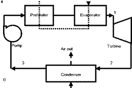
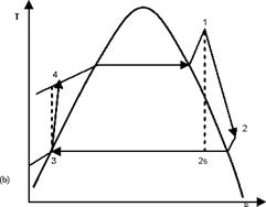
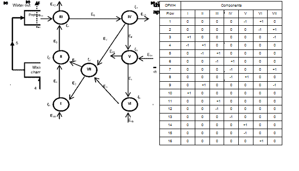
The methodology described in the previous section (§.2) is applied to four different configurations: basic Rankine cycle (Fig. 1), regenerative cycle with internal heat exchanger (Fig.
2), regenerative cycle with open feedwater heater (Fig. 3) and regenerative cycle with closed feedwater heater (Fig. 4). In Figs. 1a, 2a, 3a and 4a the flow sheet diagrams for different configurations are presented. In Figs. 1b, 2b, 3b and 4b different processes that occur in each configuration are presented. In step 2, according to Mago et a/.[4], the exergy flow graphs should be developed. The exergy graphs are illustrated in Figs. 1c, 2c, 3c and 4c. In step 3, the matrices of incidence were determined and displayed in Figs. 1d, 2d, 3d and 4d. The operating conditions:
■ Heat source: water, temperature: 77-90 °C
■ Condenser cooling medium: ambient air, temperature: 28-40 °C
 |
 |
6
 |
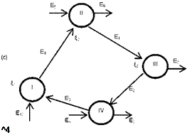 |
Fig. 1. Basic ORC: (a) Flow sheet diagram, (b) T-s diagram,
(c) Exergy flow graph and (d) Matrix of incidence.
■ Working fluid: R134a, evaporating and condensing temperatures: 75 °C and 35 °C.
■ Turbine: isentropic efficiency 70% and mechanical efficiency 63%.
■ Pumps: isentropic efficiency 80%.
■ Feedwater heater Pressure: 1.5 MPa
■ Terminal temperature difference (closed FWH): 3 °C
■ Effectiveness of the heat exchanger (IHE): 0.8
■ Restricted dead state: ambient temperature 28 °C and atmospheric pressure 0.1MPa.
■ Designed power output: 2 kW.
Along with the operating conditions above set, the following assumptions are made: steady-state conditions, no heat losses and pressure drops in the heat exchangers, the feedwaters and the mixing
unit are well insulated. In order to evaluate the flow parameters, a software EES (Engineering Equation Solver) [9] that contains the thermodynamic properties of a certain number of fluids was used. Because of lack of space, the tables of flow parameters will not be displayed here. At step 5, the thermodynamic characteristics of different nodes or elements are determined. In order to evaluate the configurations, the mass and energy balance equations are applied to each individual component to find the work output or input and the heat added or rejected.
Mass and energy balances for any control volume at steady state with negligible kinetic and potential energy changes can be expressed, respectively, by
X тгп = X mout, (12)
|
Fig. 2. Regenerative ORC with internal heat exchanger: (a) Flow sheet diagram, (b) T-s diagram, (c) Exergy flow graph and (d) Matrix of incidence. |
Q + W = X m h. — X m hn,
out OUt in ln
Where the subscriptions in and out represent the inlet and exit states, Q and W are the heat and work inputs or outputs, his the specific enthalpy and m the mass flow rate.
|
Fig. 3. Regenerative ORC with an open feedwater heater: (a) Flow sheet diagram, (b) T-s diagram, (c) Exergy flow graph and (d) Matrix of incidence. |
The last step in the exergy-topological method is the analysis of the results. The results of the calculations are displayed in Table 1 for different configurations and the following observations can be made:
■ Basic ORC
The turbine is the component that has the highest exergy losses (2.50 kW) followed by the upper heat exchangers (evaporator-preheater). It is also the component with the lowest exergetic efficiency (44.4%) and the lowest thermodynamic perfection (84.92%). The exergy loss in the turbine is due to the design. The one considered here is comparable to a scroll expander investigated in Refs.[1-2]. The upper heat exchangers have the highest degree of influence (36.03%). The system total exergy loss 4.44 kW; the degree of thermodynamic perfection is 76.88%; the thermal and exergy efficiencies are 3.703% and 8.578%, respectively.
■ ORC with regenerative heat exchanger
 |
For this configuration, the highest exergy loss still occurs in the turbine (2.504 kW). The regenerative heat exchanger has a negative coefficient of influence (-0.0396%) which means a negative effect on the system. The system total exergy loss is increased from 4.44 kW (for the basic cycle) to 4.485 kW (for regenerative cycle with the heat exchanger) and a slight decrease in the degree of thermodynamic perfection is also observed (76.88% for the basic Rankine cycle and 76.81% for the second). The negative effect of the internal heat exchanger is due to the fact that R — 134a is an isentropic fluid. The thermal and exergy efficiencies obtained in this case 3.674% and 8.512%, respectively, which are lower compared with the simple Rankine cycle.
■ ORC with open feedwater heater
As for the previous configurations, the highest exergy loss is observed in the turbine (2.497 kW). The exergy loss in the upper heat exchangers (1.024 kW) is reduced by 38% compared with the basic ORC and by 39.69% compared with the case a regenerative heat exchanger is used. The consequence of this reduction is the improvement on the upper heat exchangers’ exergetic efficiency from 75.59% for the basic ORC to 83.54%. The system total exergy loss is 3.977 kW and it is reduced by 10.43% compared with the basic ORC and this leads to the improvement of the performance of the system. The degree of thermodynamic perfection obtained is 77.51% and the thermal and exergetic efficiencies are 3.95% and 9.16%, respectively. Unlike in the previous configurations, where the upper heat exchangers had the highest coefficient of influence the most critical component here is the feedwater heater with a coefficient of influence of 76.05%.
■ ORC with closed feedwater heater
This configuration has a performance similar to the one with an open feedwater heater: turbine and system exergy losses are 2.498 kW and 4.053 kW, respectively. The degree of thermodynamic perfection of the system is 77.44%. The system thermal and exergetic efficiencies are 3.93% and 9.123%, respectively. The critical component for this configuration is the mixing chamber with a coefficient of influence of 72.96%.
|
Table 1. Thermodynamic characteristics of different ORC configurations
|
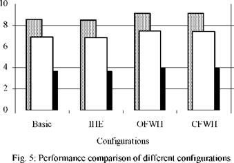
The turbine used in this study appears as the less efficient component with the lowest exergetic efficiency (<45%) and the lowest degree of thermodynamic perfection (<87%). For a desired 2 kW power output, as can be seen on Fig. 5, the regenerative ORC with open feedwater heater has the highest thermal and exergetic efficiencies and the highest degree of thermodynamic perfection.
2. Conclusion
The effects of regeneration on low-temperature solar organic Rankine cycles with R134a as working fluid were evaluated using an innovative exergy study approach called exergy topological method developed recently by Nikulshin et a/.[5-7]. Using parameters such as exergy loss, exergy efficiency, degree of thermodynamic perfection and coefficient of influence, the influence of each
component was determined and systems performance compared. The following conclusions can be made:
1. The turbine investigated yields poor performance and needs to be improved.
2. The internal heat exchanger has negative effects on the system and therefore should not be incorporated in a system utilizing R134a as working fluid.
3. A feedwater heater improves the performance of the Rankine cycle. Since a closed feedwater heater is more complex and difficult to design, an open feedwater is preferred.
4. This study has shown that the exergy-topological method is a powerful tool for the evaluation of energy-intensive systems and can be of great help when seeking for a more efficient system.
![]()
![]()
![]()
![]()
![]()
 80
80
78
76
![]()
![]() 74
74
72
70
[1] D. Manolakos, G. Papadakis, S. Kyritsis, K. Bouzianas, Experimental evaluation of an autonomous low — temperature solar Rankine cycle system for reverse osmosis desalination, Desalination 203 (2007) 366-374.
[2] A. Schuster, J. Karl, S. Karellas, Simulation of an innovative stand-alone solar desalination system using an organic Rankine cycle, International Journal of Thermodynamics 10 (2007) 155-163.
[3] V. M. Nguyen, P. S. Doherty, S. B. Riffat, Development of a prototype low-temperature Rankine cycle electricity generation system, Applied Thermal Engineering 21 (2001) 169-181.
[4] P. J. Mago, L. M. Chamra, K. Srinivasan, C. Somayaji, An examination of exergy destruction in organic Rankine cycles, International Journal of Energy Research (2008) DOI: 10.1002/er.1406.
[5] V. Nikulshin, C. Wu, V. Nikulshina, Exergy efficiency calculation of energy intensive systems by graphs, International Journal of Thermodynamics 5 (2002) 67-74.
[6] V. Nikulshin, C. Wu, V. Nikulshina, Exergy efficiency calculation of energy intensive systems, Exergy an International Journal 2 (2002) 78-86.
[7] V. Nikulshin, C. Wu, Thermodynamic analysis of energy intensive systems based on exergy-topological models, Exergy an International Journal 1 (2001) 173-179.
[8] A. Bejan, G. Tsatsaronis, M. Moran, Thermal design and optimization, Wiley, New York, 1996.
[9] S. A. Klein, Engineering Equation Solver (EES), Academic Professional V7.970-3D, (1992-2007).
O. Ayadi1*, J. Doell2, M. Aprile1, M. Motta1, T. Nunez2
^ip. Energia, Politecnico di Milano, Milan, Italy
2Fraunhofer Institute for Solar Energy Systems ISE, Freiburg, Germany
* Corresponding Author, osama. ayadi@polimi. it
Abstract
Hot weather days cause often large fresh milk defect in southern developing countries dairy farms as well as in rural areas where there is a scarcity of energy sources that could run cooling equipments. Consequently, the possibility to use solar cooling starts to be considered an attractive solution. The aim of the work presented is to develop an innovative solar thermally driven cooling concept, to be used for received fresh milk in a dairy factory in the city of Marrakech, Morocco. The work has been carried out in the framework of the EC cofunded project (i. e., MEDISCO). The system is intended for refrigeration at 5°C in hot climates, and is composed of: medium temperature collector, single effect water ammonia absorption chiller, cold storage. The peculiarity of the configuration is the high temperature difference between the chilled refrigerant temperature, about -5 °C (in consequence of using an ice storage) and the condenser temperature (ambient temperature, which could exceed 35 °C). In these conditions, the absorption chiller must be driven by a medium temperature heat source (i. e. parabolic trough collector). Moreover, the selected chiller is directly air cooled, and has the main advantage of having no water consumption, low maintenance work and no legionella problems. . TRNSYS simulations were performed to select the appropriate system configuration, size of the solar collectors’ field and the storage, heat transfer fluid and control strategy. A summary of the results is given.
Keywords: solar cooling, solar refrigeration, absorption, dairy industry.
The choice of a proper solar assisted refrigeration system for hot climates, has to take into account the boundary conditions of the site and the application — i. e., level of temperature. The aim of the work presented it has been to develop an innovative solar thermally driven cooling concept, to be used for received fresh milk in a dairy factory in the city of Marrakech, Morocco. The work, carried out in the framework of the EC co-funded project MEDISCO (MEDiterranean food and agro Industry applications of Solar COoling technologies), investigated through simulations the optimum system configuration, size of the solar collectors field and the storage, heat transfer fluid and control strategy. Further a description of the system concept, industrial application load profile, model employed and simulation results is given.
The current work focused on a technological solution selected through a methodology based on thermodynamic analysis, as suggested in [1,2]. Following the path drawn by Henning, the combination of high temperature lift, single-effect absorption chillers, and medium temperature collectors is the only choice for solar refrigeration (low temperature cold production) under the given environmental conditions (Marrakech, Morocco).
The system concepts described in this section have been newly designed for applications under the aforementioned conditions for refrigeration in the food and agro industry. Under high ambient air temperatures (e. g., higher than 35°C) in which hardly a wet cooling tower can be employed, due to high wet bulb temperatures or no availability of water, a high temperature lift system is necessary. This is even more valid if a low cold production temperature is needed e. g., in case of ice production for cold energy storage. Under those conditions only a single-effect machine can be used if driving temperatures up to approx. 200°C are available [1,2]. Therefore if the heat source is a solar system, a collector field with optical concentration will be necessary. Tracked collector systems employing optical concentration require a climate with a high fraction of direct solar radiation on the global, which is the case for the Moroccan application object of this work. These conditions correspond very much to the needs in hot, arid regions in which fresh water is costly or a scarce commodity. Further a short description of a system based on these technologies is given.
According to ref. [13], the solar collector efficiency n is defined as a function of the ratio of the difference between the average fluid temperature tv and the ambient air temperature Tmb to the incident global solar radiation on the collector ql as follows:
|
|

The constants Co, c1 and c2 are efficiency-parameter of the solar collector and are known from the
manufacture. Figure 3 shows the solar collector efficiency which depends on factor x for normal incident radiation based on measurement data from the solar cooling plant collected in the duration of 2003 to 2007.
The mean efficiency value of the solar collector field is about 0.63 and remains constant over a wide value range of the factor x, which indicates the good performance of the solar collector. The average value of the collectors’ field efficiency for the five year period is 0.28. By visual inspection of the collectors’ glass tubes, it has been found a thin layer of fouling material of residual combustion gases and other materials over the tube surfaces. These fouling materials are not removable with heavy rains.
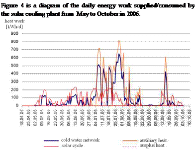
Fig. 4. Daily energy supply/consumption of the solar cooling plant.
5
The fraction of the driving heat covered by the solar collector field is referred as solar heat fraction. Until June, the solar collector field cover the heat demand of the absorption chiller. From June on, auxiliary heat from the heating network is needed to drive the absorption chiller. The reasons for the additional heat demand are bad weather conditions and the present collector field size, which is too small to cover the driving heat demand of the chiller at full load with its present completion. The five — year average heat fraction in the duration from 2002 to 2007 is 60 %. In total 89.2 MWhth heat work were consumed to operate the absorption chiller. 53.9 MWhth were generated by the solar collector field and 35.25 MWhth were provided by the heating network of the institute. But in the same period of time, the solar collector field generates also 8.13 MWhth surplus heat work, which was provided to the heating system where it substituted conventionally produced heat energy.
Figure 6 shows a 0.7-m-diameter collector (capable of delivering 600W at 350°C). The collector was sourced locally for testing.
|
Figure 6: A parabolic-solar collector |
After acquiring the collector, 250 mL of engine oil was heat to see what temperatures were possible to attain. Oil was chosen because of its high boiling point, its relatively high heat capacity (2500 J/kg. K) and its easy of availability. After heating for 15 minutes, the base of the flask holding the oil reached 180°C, and the oil within the flask reached 165°C.
|
Figure 7: Oil being heated on the solar collector |
Feeling confident we could meet with success, we attempted to fit the solar collector directly to the bubble pump, as illustrated in Figure 8. The size and location of the bubble pump made this difficult.
|
Figure 8: An attempt to connect the solar collector to the bubble pump |
A system was required to move the heat from the focal point of the collector to the bubble pump. A simple copper pipe filled with oil was used (see Figure 9), and because the heated oil would move into the bubble pump through buoyancy there was no need for an external pump.
|
Figure 9: The use of a copper pipe on top of the solar collector |
Insulation was fitted, as shown in Figure 10, to ensure the heat collected by the pipe and oil did not escape before entering the bubble pump.
|
Figure 10: The use of insulation to prevent heat loss from the system |
Figure 11 shows the complete system with the solar collector and the insulated copper pipes in place. With the solar collector on the ground, tests were performed.
|
Figure 11: The air cooling solar system |
The created control strategy permits acting directly on the flow rate by means of an ON/OFF signal, which operates directly on the pumps in order to avoid overheating conditions in winter and excessive cooling in summer. For the internal air temperature control a band of variability of 19^21°C was assumed in winter and of 25^27°C during summer.
The adopted control strategy also intervenes on the supply temperature of the radiant ceilings. It is in fact necessary to supply such terminals in a way that the surface temperatures are not too high in winter, in order not to generate conditions of thermal discomfort, nor too low in summer in order to avoid water vapour surface condensation phenomena [9].
During winter the control system determines the required inlet temperature as the sum of a first stationary term corresponding to the regime and of a second variable term [6,10]. The inlet temperature of the radiant ceiling (tiC) in stationary conditions it is the function of the external air temperature (tOA), seen as the sole constraint on the system during winter. This bond has good linear approximisation with the incline of the line which unequivocally depends upon the dispersive properties of the building shell elements [1,6]. The stationary term was determined with a prelimiary simulation campaign conducted in the absence of solar radiation and the relation obtained is the following:
tIC (steady) = -0.4726 • tOA + 29.452 (1)
Exactly because the effect of solar radiation is not taken into consideration, it is necessary to join the ON/OFF control on the feed pump to interrupt the flow rate in order to avoid overheating of the environments. The value calculated with the Equation (1) permits the regulation, in an efficient manner, of the internal air temperature when this is around 20°C, but if it moved away from such a value, for example upon morning starting of the plant, such a temperature is not sufficient in that it requires some time to work properly. In such a case, to accelerate the response, the inlet temperature value determined by the Equation (1) is correct with a second transitory term which is made to depend upon the internal air temperature (tIA) and external air [6,10]. The relations obtained are the following:
tCC (transient) = K1 • (20 — tIA) (2)
with Ki linear function of the external air temperature:
к = 0.0473 • tOA +1.019 (3)
The function of the K1 parameter is that to produce an increase in the inlet temperature of the plant decreasing with external air temperature. The transitory term gradually decreases as the internal air temperature increases, until it cancels itself for tIA=20°C. The inlet temperature of the radiant ceiling in winter is determined by the relation:
tIC =(- 0.4726- tOA + 29.452)+ [(0.0473- tOA +1.019)0 — tIA)] (4)
In summer, regulation of the inlet temperature is obtained by means of a control system which determines, hour by hour, the air dew-point temperature (tdp) within the environment. The inlet temperature is then set equal to the dew-point temperature, since the thermal resistances between the water circulating in the pipes and the ceiling surface ensures a ceiling surface temperature that is always greater than that of the dew-point [11]. A defect of this control strategy consists of the necessity of maintaining the value of relative humidity within the environment at acceptable levels. In fact, too high relative humidity leads to high dew-point temperatures, and therefore to surface ceiling temperatures that are insufficient for the complete removal of sensible loads. Preliminary simulations have demonstrated that the external air exchange, set at equal to 1.2 Volh-1, is sufficient in order to maintain, during the plant functioning times, relative humidity between 40% and 60%. Furthermore, the thermic resistance between the fluid circulating in the pipes and the ceiling surface leads to a AT« 4°C, therefore in the most critical moments this safety margin is exploited to further lower the inlet temperature and to guarantee the complete removal of sensible loads. The relation obtained for the inlet temperature of the radiant ceiling which ensures the variability of the internal air temperature between 25°C and 27 °C during summer is the following:
tIC(summer) = tdp — 2 • (tIA — 25) (5)