Как выбрать гостиницу для кошек
14 декабря, 2021
The methodology described in the previous section (§.2) is applied to four different configurations: basic Rankine cycle (Fig. 1), regenerative cycle with internal heat exchanger (Fig.
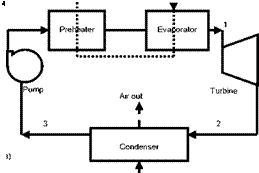
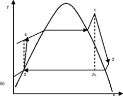
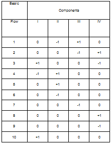
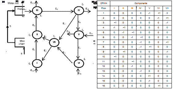
2), regenerative cycle with open feedwater heater (Fig. 3) and regenerative cycle with closed feedwater heater (Fig. 4). In Figs. 1a, 2a, 3a and 4a the flow sheet diagrams for different configurations are presented. In Figs. 1b, 2b, 3b and 4b different processes that occur in each configuration are presented. In step 2, according to Mago et a/.[4], the exergy flow graphs should be developed. The exergy graphs are illustrated in Figs. 1c, 2c, 3c and 4c. In step 3, the matrices of incidence were determined and displayed in Figs. 1d, 2d, 3d and 4d. The operating conditions:
■ Heat source: water, temperature: 77-90 °C
■ Condenser cooling medium: ambient air, temperature: 28-40 °C
 |
 |
6
 |
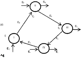 |
Fig. 1. Basic ORC: (a) Flow sheet diagram, (b) T-s diagram,
(c) Exergy flow graph and (d) Matrix of incidence.
■ Working fluid: R134a, evaporating and condensing temperatures: 75 °C and 35 °C.
■ Turbine: isentropic efficiency 70% and mechanical efficiency 63%.
■ Pumps: isentropic efficiency 80%.
■ Feedwater heater Pressure: 1.5 MPa
■ Terminal temperature difference (closed FWH): 3 °C
■ Effectiveness of the heat exchanger (IHE): 0.8
■ Restricted dead state: ambient temperature 28 °C and atmospheric pressure 0.1MPa.
■ Designed power output: 2 kW.
Along with the operating conditions above set, the following assumptions are made: steady-state conditions, no heat losses and pressure drops in the heat exchangers, the feedwaters and the mixing
unit are well insulated. In order to evaluate the flow parameters, a software EES (Engineering Equation Solver) [9] that contains the thermodynamic properties of a certain number of fluids was used. Because of lack of space, the tables of flow parameters will not be displayed here. At step 5, the thermodynamic characteristics of different nodes or elements are determined. In order to evaluate the configurations, the mass and energy balance equations are applied to each individual component to find the work output or input and the heat added or rejected.
Mass and energy balances for any control volume at steady state with negligible kinetic and potential energy changes can be expressed, respectively, by
X тгп = X mout, (12)
|
Fig. 2. Regenerative ORC with internal heat exchanger: (a) Flow sheet diagram, (b) T-s diagram, (c) Exergy flow graph and (d) Matrix of incidence. |
Q + W = X m h. — X m hn,
out OUt in ln
Where the subscriptions in and out represent the inlet and exit states, Q and W are the heat and work inputs or outputs, his the specific enthalpy and m the mass flow rate.
|
Fig. 3. Regenerative ORC with an open feedwater heater: (a) Flow sheet diagram, (b) T-s diagram, (c) Exergy flow graph and (d) Matrix of incidence. |
The last step in the exergy-topological method is the analysis of the results. The results of the calculations are displayed in Table 1 for different configurations and the following observations can be made:
■ Basic ORC
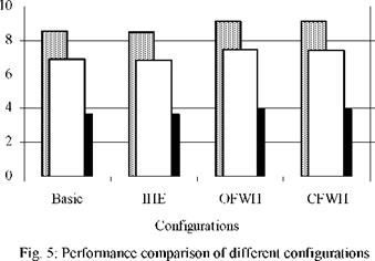
The turbine is the component that has the highest exergy losses (2.50 kW) followed by the upper heat exchangers (evaporator-preheater). It is also the component with the lowest exergetic efficiency (44.4%) and the lowest thermodynamic perfection (84.92%). The exergy loss in the turbine is due to the design. The one considered here is comparable to a scroll expander investigated in Refs.[1-2]. The upper heat exchangers have the highest degree of influence (36.03%). The system total exergy loss 4.44 kW; the degree of thermodynamic perfection is 76.88%; the thermal and exergy efficiencies are 3.703% and 8.578%, respectively.
■ ORC with regenerative heat exchanger
 |
For this configuration, the highest exergy loss still occurs in the turbine (2.504 kW). The regenerative heat exchanger has a negative coefficient of influence (-0.0396%) which means a negative effect on the system. The system total exergy loss is increased from 4.44 kW (for the basic cycle) to 4.485 kW (for regenerative cycle with the heat exchanger) and a slight decrease in the degree of thermodynamic perfection is also observed (76.88% for the basic Rankine cycle and 76.81% for the second). The negative effect of the internal heat exchanger is due to the fact that R — 134a is an isentropic fluid. The thermal and exergy efficiencies obtained in this case 3.674% and 8.512%, respectively, which are lower compared with the simple Rankine cycle.
■ ORC with open feedwater heater
As for the previous configurations, the highest exergy loss is observed in the turbine (2.497 kW). The exergy loss in the upper heat exchangers (1.024 kW) is reduced by 38% compared with the basic ORC and by 39.69% compared with the case a regenerative heat exchanger is used. The consequence of this reduction is the improvement on the upper heat exchangers’ exergetic efficiency from 75.59% for the basic ORC to 83.54%. The system total exergy loss is 3.977 kW and it is reduced by 10.43% compared with the basic ORC and this leads to the improvement of the performance of the system. The degree of thermodynamic perfection obtained is 77.51% and the thermal and exergetic efficiencies are 3.95% and 9.16%, respectively. Unlike in the previous configurations, where the upper heat exchangers had the highest coefficient of influence the most critical component here is the feedwater heater with a coefficient of influence of 76.05%.
■ ORC with closed feedwater heater
This configuration has a performance similar to the one with an open feedwater heater: turbine and system exergy losses are 2.498 kW and 4.053 kW, respectively. The degree of thermodynamic perfection of the system is 77.44%. The system thermal and exergetic efficiencies are 3.93% and 9.123%, respectively. The critical component for this configuration is the mixing chamber with a coefficient of influence of 72.96%.
|
Table 1. Thermodynamic characteristics of different ORC configurations
|
The turbine used in this study appears as the less efficient component with the lowest exergetic efficiency (<45%) and the lowest degree of thermodynamic perfection (<87%). For a desired 2 kW power output, as can be seen on Fig. 5, the regenerative ORC with open feedwater heater has the highest thermal and exergetic efficiencies and the highest degree of thermodynamic perfection.
2. Conclusion
The effects of regeneration on low-temperature solar organic Rankine cycles with R134a as working fluid were evaluated using an innovative exergy study approach called exergy topological method developed recently by Nikulshin et a/.[5-7]. Using parameters such as exergy loss, exergy efficiency, degree of thermodynamic perfection and coefficient of influence, the influence of each
component was determined and systems performance compared. The following conclusions can be made:
1. The turbine investigated yields poor performance and needs to be improved.
2. The internal heat exchanger has negative effects on the system and therefore should not be incorporated in a system utilizing R134a as working fluid.
3. A feedwater heater improves the performance of the Rankine cycle. Since a closed feedwater heater is more complex and difficult to design, an open feedwater is preferred.
4. This study has shown that the exergy-topological method is a powerful tool for the evaluation of energy-intensive systems and can be of great help when seeking for a more efficient system.
![]()
![]()
![]()
![]()
![]()
 80
80
78
76
![]()
![]() 74
74
72
70
[1] D. Manolakos, G. Papadakis, S. Kyritsis, K. Bouzianas, Experimental evaluation of an autonomous low — temperature solar Rankine cycle system for reverse osmosis desalination, Desalination 203 (2007) 366-374.
[2] A. Schuster, J. Karl, S. Karellas, Simulation of an innovative stand-alone solar desalination system using an organic Rankine cycle, International Journal of Thermodynamics 10 (2007) 155-163.
[3] V. M. Nguyen, P. S. Doherty, S. B. Riffat, Development of a prototype low-temperature Rankine cycle electricity generation system, Applied Thermal Engineering 21 (2001) 169-181.
[4] P. J. Mago, L. M. Chamra, K. Srinivasan, C. Somayaji, An examination of exergy destruction in organic Rankine cycles, International Journal of Energy Research (2008) DOI: 10.1002/er.1406.
[5] V. Nikulshin, C. Wu, V. Nikulshina, Exergy efficiency calculation of energy intensive systems by graphs, International Journal of Thermodynamics 5 (2002) 67-74.
[6] V. Nikulshin, C. Wu, V. Nikulshina, Exergy efficiency calculation of energy intensive systems, Exergy an International Journal 2 (2002) 78-86.
[7] V. Nikulshin, C. Wu, Thermodynamic analysis of energy intensive systems based on exergy-topological models, Exergy an International Journal 1 (2001) 173-179.
[8] A. Bejan, G. Tsatsaronis, M. Moran, Thermal design and optimization, Wiley, New York, 1996.
[9] S. A. Klein, Engineering Equation Solver (EES), Academic Professional V7.970-3D, (1992-2007).