Как выбрать гостиницу для кошек
14 декабря, 2021
J. Vestlund1*, M. Ronnelid1 and J. O. Dalenback2
1 Solar Energy Research Center, Hogskolan Dalama, Borlange, Sweden
2 Chalmers University of Technology, Goteborg, Sweden
* Corresponding Author, ive@du. se
Abstract
Sealed gas filled flat plate solar collectors will have stresses in the material since volume and pressure varies in the gas when the temperature changes. Several geometries were analyzed and it could be seen that it is possible reducing the stresses and improve the safety factor of the weakest point in the construction by using larger area and/or reducing the distance between glass and absorber and/or change width and height relationship so the tubes are getting longer. Further it could be shown that the safety factor won’t always get improved with reinforcements. It is so because when an already strong part of the collector gets reinforced it will expose weaker parts for higher stresses. The finite element method was used for finding out the stresses.
Keywords: Solar collectors, modelling, mechanical stresses, Inert gases
One way of getting more energy efficient solar collectors is changing the air inside the collector with a more suitable gas with respect to the unwanted heat losses. Though, a construction with an enclosed gas will cause new challenges. Since the temperature in a solar collector can vary in a range of about 240 to 500 K there will be a volume and/or a pressure variation in the gas. These variations has to be considered, otherwise they can imperil the expected life length of the construction. This study has examined a collector box consisting of an ordinary glass and an ordinary absorber in all respects expect that it is formed as a tub fixed to the glass so a cavity is formed that can host a gas.
Roll-bond panels are produced by screen printing the channel pattern on an aluminium sheet with a separating ink, rolling it together with another aluminium sheet at high pressure and high temperature and finally inflating the channels with pressurized air. Due to this process it is not possible to use precoated aluminium sheets, because the selective coating would suffer damages during the rolling process. Therefore it is necessary to apply the selective coating after the roll-bond absorbers have been built, which is only possible with a batch coating plant. Batch coating plants which can apply sputtered coatings on glass panes already exist. One aim of the BIONICOL project is to adapt such a plant of an industry partner in order to be able to coat the roll-bond absorbers.
2.2. Development and testing of appropriate heat transfer fluids
Roll-bond solar absorber were already built in the seventies and eighties, but then vanished from the market. One reason for this was the fact that corrosion occurred in some of the absorbers. Therefore one of the most important tasks within the project is the development and comparative examination of a tailor-made inhibited glycol based heat transfer fluid. The intended experimental work comprises ASTM D 1384 related corrosion tests as well as the investigation of solar fluids operated under varying field test conditions. Moreover, it is also planned to carry out corrosion tests of fluids in a closed cycle with roll-bond panels in an early stage of the project.
This design is the subject of a European patent application number EP 05255415 in the joint names of Macgregor Solar and Solartwin Ltd.
The collector is freeze-tolerant and so does not need any anti-freeze or heat exchanger. It can be directly connected to an existing heating system using fresh water. It could also be used to heat corrosive water e. g sea-water since the rubber used is resistant to corrosion.
1. Bartelsen et al , Elastomer — Metal Absorber, Development and Application, Proc ISES World Solar Energy Congress, Israel, 1999
The software uses the equations (1) to build the concentrator and the equations (2) — (19) to calculate the radiant flow density on the input aperture and the optical concentration factor [16, 17, 18, 19]. We consider that the radiation that is incident on the photovoltaic cell is fully absorbed by it. The radiant flow density on the output aperture, Brec, is calculated with the equation:
The meanings of the measures in the (20) equation are: Bconc — the radiant flow density on the
input aperture, R — the input aperture radius; r — the output aperture radius; Ninitial — the initial numbers of rays; Nabs — the number of rays on the output aperture considered to be absorbed of photovoltaic cell. The measures given by the user are: the input aperture radius, R (mm); the output aperture radius r(mm) considered to be equal to the receptive cell radius; the position of the receptive cell, H0; the initial moment of the measures, t0; the final moment of the the measurings, t1; the incrementation of the time At; the inclination angle of the roof, s; the month of the year, l; the day of the month, %.
The calculated and shown measures are: the intensity of the solar, Bn; the angle of incidence of the radiation on the input aperture, в; the density of the radiant flow in the plane that contains the input aperture, Bconc; the density of the radiant flow in the plane that contains the photovoltaic cell Brec; the optical concentration factor, Coptic; the quantity of energy that passes the input aperture during the measurements, Qconc; the quantity of energy received by the cell, Qrec ; the concentrator’s efficiency q.
The concentration is efficient if the optical concentration factor is bigger than 1. With the help of the tables or of the graphics we can determine the maximum angle of incidence 6max and the time period for which 6<Bmax.
Theoretical modeling was done applying a software generated by AEE INTEC (Gleisdorf, AUT), which provides a comprehensive theoretical mathematical description of flat-plate solar collector performance [4]. It allows for the evaluation of collector conversion factors and for the determination of efficiency graphs. For the present investigation specific functional elements, such as thermotropic layers have been implemented additionally. In real mode of operation the maximum absorber temperatures are a function of climatic conditions, incident irradiation and angle of incidence. To evaluate the frequency distribution of the maximum absorber temperatures in the course of the year a statistic module was implemented. Basically this software considers
• direct, diffuse and scattered solar irradiation reaching the absorber,
• transmission, absorption and reflection on multi-layer collector glazing including the thermotropic layer,
• solar absorption and reflection as well as thermal emission of absorber coatings,
• heat transport from absorber to fluid
• heat losses by convection, thermal conduction and radiation due to collector glazing and casing and
• climate data for Graz (for the statistic module).
Titanium oxide films were deposited on glass and metallic substrates with dc magnetron sputtering and also with pulsed dc magnetron sputtering at room temperature from 7.5mm titanium target with 99.995% purity, in reactive atmosphere with mix of argon and oxygen gas. The sputtering was carried out using a 5kW power supply, with possibility to change pulsed frequency from 5 to 350 kHz, and reverse time from 0.4 to 5ps, and reverse voltage 10% of operation voltage.
The gas argon was fed to the chamber independent of the reactive oxygen. Flows for both, argon and oxygen were regulated using Bronkorst mass flow controller, operated by Bronkorst control unit. Pressure monitoring in the sputtering chamber was made by Balzers penning and pirani with TPG 300 monitor unit.
All experiments were performed with target to substrate distance of 6cm, and depositions were started after pumping the chamber to a base pressure of 1×10⁻⁶mbar. Reflexion data were taken on a Perkin Elmer Lambda 9 NIR/UV/VIS Spectrophotometer and solar absorption was evaluated to be in account solar spectrum (AM1, 5) partition in 20 wavelength ranges of equal energy. Thermal emissivity was measured with an AE emissometer of Sevices & Services at an equilibrium temperature of 82°C and after adequate calibration. Optical properties values were evaluated with an uncertainty not exceeding ± 1%.
First experiments had in consideration the already known dependence of film morphology relatively to deposition parameters, and allowed to narrow the possible range of values variation for deposition parameters, with the final objective to reach highest as possible solar absorber selectivity [3]. Some coatings were prepared with constant oxygen flow rate and others with oxygen flow rate increasing gradually from the beginning to the end of deposition. Pulsed dc frequency and reverse time were also parameters taken in consideration.
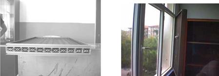
The surface temperature of the collector should have a proportional increase to get adequate airflow exit. Thus optimum geometry should be designed for the collector. For this purpose, the front and back faces of the collector are coated with foil paper both to constitute new air chambers and to stabilize the surface temperatures. (Figure 9) In which case, the selective surface isn’t muddy. It is metallic color. Once more the system is run and measurements are taken.
|
/3l |
||||||
|
1 2- 3 |
It T 6 |
? Ї. 9 |
fo H — n |
n «г /Г |
/£ n |
M — ia £1 |
Figure 9: Measurement points of the collector coated with foil paper Resultant, both air entry and air exit are seen at the collector. The collector coated with foil paper doesn’t absorb heat as much as muddy selective surface from infrared radiation lamps. The system keeps less heat therefore entry velocities decrease significantly and pressure difference comes to normal values and air exit is seen. Thereby measurements could be taken from all chambers and holes. (Table 2)
Consequently, the back and the front face of the aluminum profile is enclosed with it’s standard cover. In this case, new chambers are formed for air entry and exit. (Figure 10) The wavelength selective coating is applied to the front face of the collector profiles that have a low emissivity of energy in the infrared wavelengths. Moreover the back face of the collector is insulated to generate effective convective air flow on the basis of the test results. The front and back face of the collector are framed by aluminum framing. (Figure 11) The insulated backing of the solar collector serves the dual function of blocking heat transfer between the classroom and the back of the profiles (and air chambers) and insulating the window area to reduce heat transfer from the classroom to the outdoors. [4]

|
|

Figure 12. F*yranometer on the collector.
|
Table 2. The measurements of the collector coated with foil paper.
|
mance of the collector geometry is analyzed using Computing Fluid Dynamics (CFD). Measured temperature and velocity values at the exit of the collector are compared with CFD analyze results and they are coherent. [5]
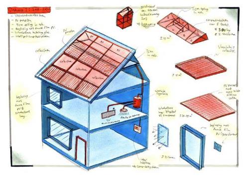
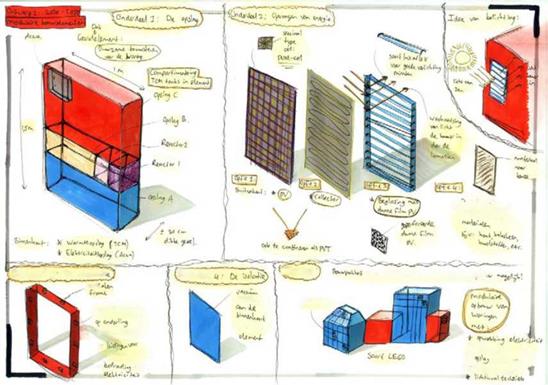
The trends and ideas resulting from the series of workshops were analysed and combined into twelve sketches of the solar thermal collector of the future. The purpose of these sketches was to visualise the outcomes from the workshop, and to get an impression of the consequences and feasibility of the realisation of these trends. In a multi-criteria analysis, the sketches were analysed and ranked. The highest-scoring two sketches were then worked out into two primary concepts, one for the longer term, aimed at 2030, and one for the shorter term, aimed at 2015.
 |
The first concept, aimed at 2015, is based on a passive house, which roof is covered with a roof — integrated side-by-side solar system with both PV panels and vacuum tube collectors. The heat generated in the collectors is stored in a thermochemical seasonal heat storage. The energy flows, both heat and power, are regulated by an intelligent energy management system. This system is able to fully provide the domestic energy use (assumed to be 6.5 GJ for space heating, 12 GJ for DHW, and 3,500 kWh for electricity), covering the energy demand of both the user and the building itself.
The second concept, aimed at 2030, is based on durable, modular construction elements, in which energy production, energy storage, building insulation, and an indoor climate system can all be integrated. By choosing the appropriate construction elements, the building can be completely tweaked to the user’s particular demands. Although the energy production of this concept is of course very dependent on the chosen configuration, many energy-producing configurations are possible, in which the total energy production exceeds the total domestic energy use.
4 <-U* b-k«W
 |
 |
|||
^ »kvK. llbrfi
The WAELS project is a cooperation between ECN, TNO, and the Eindhoven University of Technology, and partly funded by SenterNovem, an agency of the Dutch Ministry of Economic Affairs. The work described in this abstract was partly carried out by an Industrial Design student of the University of Twente.
 Journal of Heat and Mass Transfer 48 (1) (2005) 53-66.
Example (a) in Fig. 8 shows a thermosiphon collector with blow-moulded absorber of PE. (b) and (c) are flat-plate collectors with 10 mm PC twin-wall sheets as collector cover. In example (b) is
the absorber made of silicone rubber tubing partly compressed between metal plates. A drain-back collector with stiff, extruded absorber plate of polyphenylene ether/polystyrene (PPE/PS) blend is shown in (c). Example (d) is a solar air collector of PC where the extruded structure has a transparent surface as collector cover and a black rear side as absorber. A transparent, hollow roof tile of polymethyl methacrylate (PMMA) was developed as solar collector with a black liquid as absorber and heat carrier (e). Example (f) represents a hybrid absorber of EPDM pipes pressed into a metal, modular roof system with omega-shape profile; it is available with/without glazing and as a hybrid PV/solar thermal collector. The examples (c), (d) and (f) in Fig. 8 are modular systems of polymeric or hybrid-polymeric collectors, which are available in various lengths and designed for replacing conventional roof — or facade covers.
|
Fig. 8. Glazed collectors with polymeric components (Img. source: Solco (AUS), Solartwin (UK), Solarnor (N), PUREN Gmbh (D), Geasol (SI), MAAS Profile Gmbh & Co (D)) |
If ventilation should be applied as an overheating mechanism in polymeric collectors, it is necessary to limit heat losses when the collector is operative. Hence a flap at the top of the collector frame was introduced, which should be opened when a critical temperature in the collector/of the absorber is reached (Fig. 1). Due to the high thermal expansion coefficient of polymeric materials (~10-4 K-1), the temperature of the absorber itself and its longitudinal
expansion can be used to trigger the opening of the flap. This is a simple, self-controlled mechanism, which will also work during power failure.