Как выбрать гостиницу для кошек
14 декабря, 2021
The surface temperature of the collector should have a proportional increase to get adequate airflow exit. Thus optimum geometry should be designed for the collector. For this purpose, the front and back faces of the collector are coated with foil paper both to constitute new air chambers and to stabilize the surface temperatures. (Figure 9) In which case, the selective surface isn’t muddy. It is metallic color. Once more the system is run and measurements are taken.
|
/3l |
||||||
|
1 2- 3 |
It T 6 |
? Ї. 9 |
fo H — n |
n «г /Г |
/£ n |
M — ia £1 |
Figure 9: Measurement points of the collector coated with foil paper Resultant, both air entry and air exit are seen at the collector. The collector coated with foil paper doesn’t absorb heat as much as muddy selective surface from infrared radiation lamps. The system keeps less heat therefore entry velocities decrease significantly and pressure difference comes to normal values and air exit is seen. Thereby measurements could be taken from all chambers and holes. (Table 2)
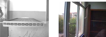
Consequently, the back and the front face of the aluminum profile is enclosed with it’s standard cover. In this case, new chambers are formed for air entry and exit. (Figure 10) The wavelength selective coating is applied to the front face of the collector profiles that have a low emissivity of energy in the infrared wavelengths. Moreover the back face of the collector is insulated to generate effective convective air flow on the basis of the test results. The front and back face of the collector are framed by aluminum framing. (Figure 11) The insulated backing of the solar collector serves the dual function of blocking heat transfer between the classroom and the back of the profiles (and air chambers) and insulating the window area to reduce heat transfer from the classroom to the outdoors. [4]

|
|

Figure 12. F*yranometer on the collector.
|
Table 2. The measurements of the collector coated with foil paper.
|
mance of the collector geometry is analyzed using Computing Fluid Dynamics (CFD). Measured temperature and velocity values at the exit of the collector are compared with CFD analyze results and they are coherent. [5]