Как выбрать гостиницу для кошек
14 декабря, 2021
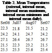
The two summers of 2006 and 2007 reach external temperatures quite high for Lisbon, above 35°C achieving even 40 °C during day time. In these two summers the mean temperatures inside the building varies between 24°C and 25.4°C, for mean maximum temperatures from 26.4°C up to 28.1°C (see table 2). These temperatures correspond to the rooms in the south part of the building which are the hottest one, in the north part of the building, like in winter a difference in these location can achieve 2°C.
|
Julb06 |
Aug06 |
|
|
Text |
23.7 |
24.5 |
|
Tint |
25.1 |
25.4 |
|
Tmax |
27.3 |
28.1 |
|
T ■ min |
23.3 |
23.3 |
|
T daily |
26.3 |
26.8 |
 |
In figure 9, for the hottest month of summer 2006, the hourly temperatures are presented for outside air temperature (light blue) and for the three building levels. In the hottest days, with outside air temperatures above 35°C the air inside the building in the upper level reaches around 30 °C (mean maximum of 31.6°C). In particular in 6 of August for an outside air temperature of 40°C, the 3 level reached 30°C in the upper floor, 28 in the middle floor and 24 in the basement.
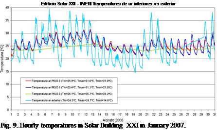 |
The basement is of course the one where the temperatures are the best (in green in figure 9). For the whole month a very smooth line between 23.2°C and 24.1°C has been measured.
The ground temperature during summer period varies between 17.5°C to 19.5°C which is a very interesting temperature for cooling purposes. Figure 10 presents the hourly temperatures for the hottest month in summer 2006 (August) in the system and boundary. External air temperatures reaching in August 6, 39.7°C (light blue), the ground temperature almost constant with a mean temperature of 19.1°C (dark red), and the temperatures in the pipes: red near the inlet tube (mean temperature of 21.1°C); green in the middle of the tube (mean temperature of 20.6°C) and blue near the enter of the building (mean temperature of 20.7°C).
|
Edificio Solar XXI — INETI Temperatures de Ar nos Tubos Enterrados vs interior e exterior
Fig. 10. Hourly temperatures in the buried pipe system in August 2006. |
|
Edificio Solar XXI — INETI Temperaturas de ar nos Tubos Enterrados vs interior e exterior
Fig. 11.Influence of the cooling system in air temperatures (August-September 2007). |
Figure 11 presents the behaviour of the system when operated by the user in some particular days (from August 27 to September 8, 2007). There are two different modes of operation with circulation ON (4-9 Sept) and OFF. During the ON period, the temperatures incoming in the building (blue colour in the graph) can decrease up to 5°C when the circulation in the pipes are operating. In terms of air temperature in the room this can correspond to a decrease up to 3°C (red colour) see September 4.
1.1. Experiment facility
Roof testing materials in four measurement boxes (inside measurement 300^300) were set up in the upper part of the center of the experiment facility shown in Fig.2. A pair of roof testing materials W (perspirable roof material + light structural roof) and a pair of roof testing materials D (light structural roof only) were made. The temperature and the heat flow rate were measured and compared by the
![]()
 |
couple (D and W), and the rate of evaporation was measured from the weight change of the measurement box of the other couple. Fig.3 shows measurement point of the temperature and the heat flow rate. The experiments were performed in Tsu City, Mie Prefecture, Japan in summer of 2006. The specific sense temperature of the hydrogel was set at 25-30 °С, by taking the actual outdoor condition in summer into account. The water absorption magnification was set to be about 150 times of the weight of the hydrogel, by supplying water in the night time, once a day.
Fig.4 shows the example of the experimental results of each measurement box. By comparing measurement results of the boxes D and W, the decrease rate of the temperature and the heat flux (heat gain) due to the evaporative cooling of perspiration are as follows, (as each maximum value during the experiment period for the sample (1)), the roof surface temperature (D2-W2) is about 32 °С, surface temperature under the box (D4-W4) is about 4 °С, heat flow rate of steel plate outer surface (DF1- WF1) is about 107W/m2, surface heat flow under the box (DF2-WF2) is about 13W/ m2, and for the sample (2), the roof surface temperature (D2-W2) is about 33 °С, surface temperature under the box (D4-W4) is about 4 °С, heat flow rate of steel plate outer surface (DF1-WF1) is about 137W/ m2, surface heat flow under the box (DF2-WF2) is about 13W/ m2. The maximum evaporation rate is 1.02kg/(m2-h) in the sample (1) and 1.08kg/(m2-h) in the sample (2). The thermal effectiveness due to the evaporative cooling is large in each sample of the perspirable roof. For each sample, evaporation occurs in conformity with the relationship between the surface temperature of the sample and the specific sense temperature of the hydrogel.
The analysis method adopted is of calculating multi-room temperature, heat load and ventilation rate with the use of simultaneous non linear equations of room heat balance, room air rate balance, wall outer and inner surface heat balances, with room temperature, room pressure, wall outer and inner surface temperatures for each room set as unknown quantities, as shown in literature[4,5]. As for the heat conduction calculation of the wall, the finite difference method (implicit scheme) is used. Fig.5
shows the calculation flow of the autonomous perspiration on the wall surface. The calculation time interval is assumed to be 1hr in this calculation.
The semitransparent PV laminate has three layers: the exterior layer is clear glass, the middle layer is formed by the PV cells and EVA in the spaces among them, and the third layer can be translucent Tedlar or glass, depending on the typology. The rear glass varies from a single glass in the simplest case, to a triple glaze. The governing equation and the boundary conditions within each layer are:
dT
pcp — — V-(kVT ) = Q
T = Te in x = ePV (4)
kVT • n = hco (To — Tc) + hrcs (Ts — TcJ) in x = 0
Where: p is the density of each layer (Kg/m3); cp is the specific heat coefficient (J/Kg°K); Tis the temperature of the layer (°K); к is the thermal conductivity (W/m°K); Q is the volumetric heat source (W/m3), Te is the temperature of the last node (°K); Tc is the temperature of the first node (°K); Ts is the radiative sky temperature (°K); h co is the average convection heat transfer coefficient between the PV and the exterior (W/m2°K); hrsc is the radiation heat transfer coefficient (W/m2°K) and epv is the thickness of the PV laminate (m). Equation 4 is solved using a finite element scheme in one dimension. The temporary term is discretized using the trapezoidal rule. By deriving the weak form of Equation 4 and applying the Galerkin method, we can obtain a discretized system of equations defined as:
[A\rn+e]=rn+e]
![]() Where: [A] is the coefficients array; [T+e>] is temperatures vector at time step=n+0; [f+&] is the residual array; n is the time step number; 0is the temporal coefficient. When 6=1, the backward Euler scheme is used and when в=1/2 the Crank-Nicolson scheme is used. The array [A] is three-diagonal. The values of the terms in each array depend on the layer. The physical properties of the second layer of the PV laminate (PV cells and EVA) are affected by the packing factor (P). In the case of the rear glass, the FEM discretization will be the same as the PV laminate, but the boundary conditions will be the opposite (Dirichlet at x=0 and Newmann at last node). The system of equations in both domains is solved using a direct three-diagonal algorithm (TDMA). Once the temperatures of each node are obtained, the conduction heat flux towards the air channel q” cond and q”g 1 cond are computed using
Where: [A] is the coefficients array; [T+e>] is temperatures vector at time step=n+0; [f+&] is the residual array; n is the time step number; 0is the temporal coefficient. When 6=1, the backward Euler scheme is used and when в=1/2 the Crank-Nicolson scheme is used. The array [A] is three-diagonal. The values of the terms in each array depend on the layer. The physical properties of the second layer of the PV laminate (PV cells and EVA) are affected by the packing factor (P). In the case of the rear glass, the FEM discretization will be the same as the PV laminate, but the boundary conditions will be the opposite (Dirichlet at x=0 and Newmann at last node). The system of equations in both domains is solved using a direct three-diagonal algorithm (TDMA). Once the temperatures of each node are obtained, the conduction heat flux towards the air channel q” cond and q”g 1 cond are computed using
Fourier’s law.
In this paper energy balance simulations were performed for one electrochromic and two static solar control windows. The visible transmittance of the electrochromic layer was modulated using four different control strategies, one for energy optimization and three based on incident solar radiation limits during office hours and energy optimization during unoccupied hours. This paper does not provide an optimized control algorithm, but general trends for a few control strategies are described. For example adjusting the control strategy to the time of the day and seasonal solar irradiance and temperature changes, have been shown beneficial from an energy perspective. It is clear that the switchability of electrochromic coatings is advantageous, but that multiple factors, such as visual comfort, user needs, climate, and orientation, have to be considered for optimum performance. In this paper it was shown that a simple window simulation tool can be used to estimate how some of these factors affect the energy balance.
References
[1] S. E. Selkowitz, Integrating advanced facades into high-performance buildings, Proc. Glass Processing Days, Tampere, Finland, 52-59 (2001)
[2] C. G. Granqvist, Handbook of inorganic electrochromic materials, Elsevier, Amsterdam (1995)
[3] N. L. Sbar, Electrochromic smart windows — the power to change, Proc ICCG7, Eindhoven, The Netherlands, p 351, (2008) (Extended Abstract)
[4] J. Karlsson, B. Karlsson, A. Roos, Control strategies and energy saving potentials for variable transmitting windows versus static windows, Proceedings, EuroSun-200, Copenhagen, June 19-22, (2000).
[5] S. Papaefthimiou, E. Syrrakou, P. Yianoulis, Energy performance assessment of an electrochromic window, Thin Solid Films, 502, 257-264 (2006)
[6] A. Roos, D. Covalet, X. Fanton, M-L. Persson M., W. Platzer, T. R. Nielsen., H. R. Wilson, M. Zinzi, M. Kohl, M. Heck, B. Chevalier, Energy Performance of Switchable Glazing — IEA Solar Heating and Cooling Programme, Task 27, Proceedings 10DBMC International Conference On Durability of Building Materials and Components, LYON [France] 17-20 (2005)
[7] J. Karlsson, B. Karlsson, A. Roos, A simple model for assessing the energy performance of windows, Energy and Buildings, 33, 641-651 (2001)
[8] J. Karlsson, WinSel-A general window selection and energy rating tool, Proc. WREC VI, Brighton, (2000)
[9] EN410, European Standard, Glass in Building — determination of luminous and solar characteristics of glazing,
[10] EN673, European Standard, Thermal insulation of glazing — Calculation rules for determining the steady state U-value of glazing
[11] A. Roos, P. van Nijnatten, M. G. Hutchins, P. Polato, F. Olive, C. Anderson, Angular dependent optical properties of low-e and solar control windows — simulations versus measurements. Solar Energy, 69 (suppl.), No 1-6, 15-26 (2001)
[12] http://windows. lbl. gov/software/window/W5UserManual. pdf (accessed 2008-08-15)
Buildings use 40% of the total energy in the US and European Union, [4]. Thus, any development strategy considers, in dedicated chapters, guidelines or targets for building development. Different concepts are proposed such as zero energy building (ZEB) or net zero energy building, low energy building, autonomous building, passive house that characterize the energy used/lost in building benefiting on different saving/renewable energy solutions, comparing with a traditional house using energy based on fossil fuels. The concepts are not descriptive and there are national standards mainly for the energy used for heating because in many climatic zones it represents the largest energy used. Furtherer development runs towards energy plus houses that generate an energy surplus due to a combination of very low losses (energy conservation) and efficient use of renewables. All these concepts are already implemented in demo buildings or in larger demo communities as the Sustainable Campus in Los Angeles Community College, [5] or the Plus Energy Village in Freiburg. For passing from the demo stage to the large implementation, scientific and technical progress is required along with a supporting legal and financial frame. This is why the EU COM (2008) 30 Directive promotes the idea of passive, low or zero energy building as a solution for reaching the 20/20/20 targets.
In a low energy building the energy requirement for space heating ranges from 30 to 20 kWh/m2year (German standard) or is set as 42 kWh/m2year (Swiss standard). The use of renewables is mainly addressed to for heating/cooling via solar thermal systems, alone or combined with heating pumps. Studies, [6], have proved that in temperate climatic regions, the active solar heating via solar-thermal collectors is efficient in transient seasons (autumn, spring) and the peak (in winter) is well supported due to the heating pump.
The implementation of photovoltaics (PV) is of importance in promoting zero energy buildings but has a significant contribution in the thermal energy balance of low energy buildings, too. Building integrated photovoltaics, [7], or Active Building Envelopes, [8], are investigated for calculating their efficiency and modelled in correlation with climatic data for the novel buildings design.
Modelling the (thermal) energy consumption in low energy buildings is done considering the energy flows and the consumption analysis, based on commercial software (TRANSYS, ISOFOTON, CENSOLAR) or based on other software developed according to the needs, [9-10]. The complex approach requires specific climate variables, the solar-thermal installation characteristics, the installation conditions corroborated with the consumption needs. Based on the data accuracy and the
algorithm used for data refining (average values calculated for different time steps) the results (mainly the sizing of the solar-thermal system) are closed to the real building needs or lead to overdimensioning (and supplementary costs).
Thus, designing a low energy building uses a combination of climatology, thermodynamics (especially heat transfer), civil engineering and energy management, applied to renewables integration.
P. Hollmuller1*, P. Gallinelli2, B. Lachal2, W. Weber2
1 SESUL / IDL, Universidade de Lisboa, Campo Grande, 1749-016 Lisboa, Portugal
2 Pole en Sciences de l’Environnement, Universite de Geneve, 1227 Carouge / Geneve, Switzerland
* Corresponding Author, pierre. hollmuller@fc. ul. pt
Objective of this study is to compare the cooling potential of diverse passive cooling techniques linked to ventilation: controlled thermal phase-shifting (a recently discovered phenomenon), air-soil heat exchangers, evaporative cooling, and direct night cooling. The potential of these techniques is investigated for the case of an administrative building located in a moderate climate, with a specific attention to urban versus rural location, as well as normal versus extreme summer (of type 2003). Simulated building response is analyzed for a variety of constructive and operational configurations (solar protection, thermal mass and insulation, internal gains), in free floating mode as well as with auxiliary cooling backup. Keywords: passive cooling, ventilation, building simulation.
1. Introduction
In most parts of Europe, electricity demand for air-conditioning is in rapid increase. Limitation of this demand requires as well adequate architectural and constructive measures (reduction off the solar and internal gains, access to the thermal mass), as development of passive techniques.
Subject of a recent discovery, controlled thermal phase-shifting of the day/night oscillation carried by an airflow is a promising phenomenon for cooling with very low electric consumption: by delaying the cool night peak by 8-12 hours, almost without dampening, latter becomes available in the middle of the day, when the demand for cold in the building is at its maximum.
In spite of its attractive temporal specificity, latter technique must be compared with other passive cooling techniques, in particular those which also make use the ventilation system (night ventilation, buried pipe systems, evaporative cooling). As for all of these techniques, the effective cooling potential further intrinsically relates to the building design and response.
Objective of this study is to clarify above mentioned points for the case of administrative buildings, located in moderated climates, as investigated here on base of a series of meteorological datasets for the Geneva region.
This paper resumes the findings of a research financed by the Swiss Department of Energy.
Two scenarios are considered for the cost of the PV systems: 400 €/m2 and 600 €/m2. This significant difference of values is due to the large variety of PV systems available in the market and also due to the scale factor: the cost of PV decrease with the increment in purchase volume (implementation more favourable for large areas). The system cost includes the PV panels and related equipment with installation cost.
From a weighted average for pavilion and non-pavilion schools, the cost to implement PV system
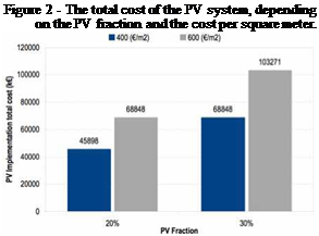
is between 270-400k€ per school (depending on the PV fraction) for the 400 €/m2 scenario and 400-600k€ for the 600 €/m2 scenario. The cost of implementation in the full 172 school set is shown in Figure 2.
2.1 PV electricity production and CO2 emissions
The estimation of the electricity produced from PV takes in account the following considerations:
• PV area fraction: 20 or 30%
• Location (different levels of solar irradiation, data from Solterm [5])
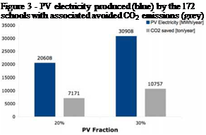 |
Then, from the PV area (for both PV fraction scenarios) and the annual capacity of production of electricity for each district (kWh/m2), the total annual capacity of production of electricity was computed. For the 172 schools the annual electrical production of 21-31 GWh, for a PV fraction of 20%-30% respectively, see Figure 3. The total PV capacity for 172 schools is estimated at approximately 144 000m2 or 20 MWp, almost twice the installed capacity in the large PV facility in Serpa (11 MWp).
2.2 Impact on the Energy Balance of Typical Schools
The average consumption of a standard school is 13 koe/m2.year [3]. We define electrical autonomy for a school as the ratio between the potential of PV electricity production and the total electricity consumed by the school (PVe/Te). Since the PV to floor area ratio for pavilion type schools is more favorable (compared to NP) the PVe/Te ratio is much more favorable for this school type.
|
Figure 4 — Impact of PV on the electrical autonomy of the schools
|
These gains on electrical autonomy will produce an impact on the energy classification of the school buildings according with the national system of energy certification and interior air quality in buildings [2]. Following the standard simulation methodology and discounting the PV production from the primary energy consumption, the energy classification from a typical school
[3] is improved, up to an A+ level, see figure below.
|
Figure 5 — Impact of PV on the energy class of the schools. The school with no PV is taken as reference.
|
4.1. Optical transmittance/absorbance curve of Sn, Mn andFe halide films:
The optical transmittance/absorbance curve for Sn, Mn and Fe halides are shown in Figs. 1, 2 and 3 respectively. These curves show that these films are highly absorbing in the ultra violet region (0.3-0.45 pm) 1-3. The films also show very high transmittance in the visible
region (0.4-0.85 gm), while they are reflecting in the near infrared region (0.85-1.0 gm). The maximum transmittance at the end of the visible region are 88%, 86% and 76% respectively for Sn, Mn and Fe halides at 820 nm. On the other hand the films have very low absorbance in the visible. Visible absorbance range from 0.06 to 0.22 x 10⁶ m-1 for Snl2; 0.07 to 0.28x 10⁶ m-1 for MnBr2 and 0.12 to 0.58 106 m-1 for FeCl2. UV absorbance ranges from 0.22 to 0.58 m-1 for Snl2, 0.28 to 0.55 m-1 for MnBr2 and 0.58 to 0.93 m-1 for FeCl2, while NIR absorbance is from 0.06 to 0.33m-1 for Snl2, 0.07 to 0.31m-1 for MnBr 2 and 0.12 to 0.26m-1 for FeCl2.
Thus the behaviour of the spectral curves show that these films will allow transmission of the visible portion of the solar spectrum but will shut off the transmission of the ultra violet and near infrared portions of the spectrum. This is because transmittance of about 60% in the visible region is high enough to allow high level of ‘daylight’ (luminance) into building interiors. Also, an absorbance of about 0.6 per cm in the UV region and about 0.35 per cm in the NIR region are high enough to cause substantial attenuation of both UV and NIR radiation and this will reduce their transmissions, and hence shut off high energy UV and high temperature NIR radiations from entering the building interiors [3].
Czech Technical University in Prague, Dept. of Environmental Engineering, Faculty of Mechanical
Engineering, Technicka 4, Prague 6, Czech Republic
* Corresponding Author, tomas. matuska@fs. cvut. cz
Paper is focused on potential shading problems of solar collectors integrated into building facades in the urban environment, especially in housing estates. Parametric shading analysis of facades for two basic types of buildings configuration (row buildings, tower buildings) has been performed. Case study of facades shading by surrounding objects has been evaluated for three different housing estates in Prague (Czech Republic) with different period of development and density of the buildings. While old dense housing estate case results in 20% annual decrease in solar irradiation incident on facade, the newer housing estates show just several percent decrease.
Keywords: building integration, facade collector, shading analysis, solar irradiation
1. Introduction
Solar domestic hot water (DHW) systems and solar combisystems for DHW and space heating in residential buildings have a high potential in central Europe. Solar thermal systems show a dramatically increasing trend being more and more applied in modern family houses. Number of solar systems applications for newly built and retrofitted blocks of flats especially in urban environment of larger cities is very low in Czech Republic but strong development is expected with respect to financial support in the frame of European Operational Programmes for use of renewable energy sources.
Placing the solar collectors on blocks of flats results in number of aspects that designer has to take into account. On the one side, there could be problems to bring a sufficient collector area on the roof of the building. There are often collisions with already installed building furnishings and devices (machine rooms for elevators, exhaust heads of ventilation systems, antennas cell operators or WiFi providers). However, the collector field placed above the roof affects the compact shape of the building, it can be visually disturbing and it can result in rejection of the whole solar system by the responsible architect.
On the other side, a large area for solar collector application is offered by building facades. The integration of solar collector into building facade envelope instead of separate installation on the flat roof represents a transition from the building envelope considered as an energy loss to envelope being a heat source (energy active envelope). Coupling the function of building envelope with solar thermal collector leads to a concept of multifunctional facade elements providing several functions (synergy effects). Trends focus in holistic approach supposing that solar collectors form an essential part of building facade constructions.
However, solar facade collectors are more sensitive for potential shading due to vertical position of surface receiving solar energy. This fact is problematic especially in the complex and dense housing estate structures in the urban environment.
 |
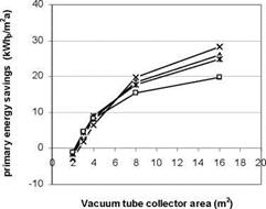 |
The area of the collector is varied between 2 and 16 m2, and for each, the volume of the storage vessel is varied between 0.15 and 10 m3. Although the latter value is perhaps a little high for a single family house, the simulations are carried out to show the potential and limitations of the system. The results are compared to those of the base case, where a 3 m2 vacuum collector with a 150 l storage vessel is used solely for DHW production. The added savings on primary energy demand for space heating, DHW and hot fill are shown in fig 3.
Fig. 3. Savings on primary energy — compared to base case — as a result of the solar collector contributing to space heating, DHW and hot fill as a function of collector area and at different storage vessel sizes
The solar contribution to the total primary energy savings for space heating is calculated assuming that in the absence of a solar collector, the heat has to be generated with a boiler with an efficiency of 95% (on lower heating value). Similarly, for DHW the efficiency of the boiler is assumed to be 75%. For the hot fill the savings are calculated assuming that in the absence of the solar collector, the electricity has to be generated in a power plant with a primary energy efficiency of 50%. When the solar collector cannot supply enough heat for the hot fill, there is still a gain in primary energy because the heat is then generated by the boiler with an efficiency of 75% rather than in the electricity plant at 50%.
From Figure 3 it appears that even with rather modest collector sizes in the order of 8 m2, there is a substantial saving on primary energy of 15-20 kWh/m2a over the base case. This corresponds to a solar fraction of about 45% of the total heating demand for space heating, DHW and hot fill. It also appears that at this collector area, the size of the vessel is of secondary importance, as long as it is at least 0.6 m3.