Как выбрать гостиницу для кошек
14 декабря, 2021
Assuming that through the use of double-facade walls it is possible to decrease the building’s demand for air conditioning and mechanical ventilation, as well as to have net energy gains from solar energy for its heating, the overall energy balance of the building should improve. Few published studies on the subject, however, fail to wholly support this thesis.
K. Daniels published a study which compares the energy cost of an office building with a given set of parameters describing its internal physical environment, dependent on the chosen model of facade [2]. Altogether, 5 options were taken under consideration:
• Double facade with a box structure and insulating glass in the interior wall — no.1
• Double facade with a box structure, insulating glass and a thermal filling in the interior wall — no.2
• Single facade with insulating glass and a thermal filling in the interior wall — no.3
• Single facade with a glass Luxguard Natural — no.4
• Single facade with a glass Climasol Neutral — no.5
The presented cumulative diagram (Fig.6) sums the different elements of energy cost (heating, cooling, lighting etc.) and shows that the difference between two best results for a double facade
(2) and a single facade (5) is not more than 8% (sunshades were not taken into consideration).
D. Richards published a study on comparative cumulated energy expenditures of buildings with different types of external walls, including double facades [9]. In comparison to a single facade with single glazing and without external insulation (under today’s thermal insulation standards — discontinued), energy savings from using double facades reach 75%. When single glazing was replaced with low emission insulation, these gains fall to 50%. Should an additional external system of protection from the sun’s radiation be used, same levels of energy consumption are recorded (the difference is within 2%). In the case of buildings which use external shading systems (low buildings), much less expensive single facades can be a serious competitor for double facades. Comparisons should then be made in other areas, such as protection from the noise or the aesthetics of both solutions.
4. Conclusions
The analysis of utility value of double facades is related to their ability to take advantage of natural weather conditions (sun and wind). It points to the following advantages and shortcomings of their application in buildings (tab.1):
|
Tab. 1 Advantages and shortcomings of double facades
|
This enumeration allows us to conclude that double facades largely meet the requirements of interactive walls. Such was the dominant view emerging from publications dating from mid 1990s, when such solutions were at the top of their popularity. However, the experience from exploitation of these double-facade buildings over the next 10 years do not allow for such one-sided opinions.
The main problem is that the advantages stipulated above can be attained only with a proper design process, which requires much higher inputs of knowledge, experience and cost that in the case of other types of walls. It also necessitates interdisciplinary research involving simulation, testing and comparison of different types of solutions to choose optimal options. In the case of many constructed buildings, these were deliberately omitted [11], but other advantages came to the fore: acoustic properties of double facades (good insulation from external noise even when windows are opened) and their architectural value. These buildings are characterized by above-the-average energy consumption and offer a number of discomforts for their users, including overheating in summer. Buildings that took advantage of interactive double facade walls (such as the Commerzbank head office in Frankfort, RWE office building in Essen, Post-Office in Bonn) have better exploitation characteristics, even though these are slightly worse than planned. Therefore, even a careful process of designing is prone to error. The functioning of double facades is dependent on many elements and feedbacks with other elements of the building (buffer zones, installation systems), which are hard to precisely assess beforehand. It also requires important outlays for cleaning, maintenance and repair. Their effectiveness also depends on the conscientiousness of their users and rationality of their behaviour. Furthermore, each building should be treated separately and optimized for its shape and location on site.
Perhaps technological development will allow for the design process to be both more simple and effective. However, it may also be that progress in combining glass with nanomilimeter layers, which improves its utility value, will allow to construct a wall, in which control over internal environment of the building will take place within the microscale of the glass pane. The sense of creating multilayer, complex structures, such as double facades, could then be seriously questioned.
Refercences
[1] Compagno, „Intelligent Glass Facades“, Birkhauser Publishers, Basel-Bostn-Berlin1997.
[2] K. Daniels, „Low-Tech Light-Tech High-Tech Building in the Information Age“, Birkhauser Publishers Basel-Boston-Berlin 1999.
[3] K. Daniels, „The technology of Ecological Building”, Birkhauser Verlag Basel-Boston-Berlin 1997.
[4] Double-Skin Walls”, collective research of Ecole Polytechnique Federate de Lausanne, Institut de Technique du Batiment, Departement d’Architecture 1999.
[5] G. Gogolok,„Sciany oslonowe dwupowlokowe” [Double-layer facade walls], conference materials Nowoczesne lekkie sciany oslonowe i okna” [Modern light walls and windows], Mrqgowo 1999.
[6] V. Lerum „High Performance Building”, John Wiley&Sons, New Jersey 2008.
[7] R. D.Lieb, E. Oesterle, “’Das Dusseldorfer Stadttor’ Exercising an Integrated Approach to Double Facade Planning”, 1999.
[8] Oesterle, Lieb, Lutz, Heusler, „Double Skin Facades, Integrated Planning”, Prestel Munich-London-New York 2001.
[9] D. Richards, “An Integrated Approach to Sustainability”, “Dimensions of Sustainability”, E&FN SPON 1998.
[10] K. Zielonko-Jung “Podwojne elewacje szklane we wspolczesnej architekturze” [Double glass facades in contemporary architecture], Ph. D. thesis, Faculty of Architecture, Warsaw Polytechnic, Warszawa 2003.
[11] K. Zielonko-Jung „Uwarunkowania technologiczno-ekologiczne stosowania scian dwupowlokowych — tendencje rozwojowe” [Technological and environmental determinants of double-facade walls — development trends], unpublished research, Faculty of Architecture, Warsaw Polytechnic, Warszawa 2005.
i Published research grant financed (2007-2009) by the Ministry of Science and Higher Education, Fusion of traditional and advanced technologies as a new environmental orientation in contemporary architecture”.
The solar collector and the storage vessel were modelled in Matlab. A collector heats the water in the primary loop, shown on the left in figure 2, allowing a temperature stratification within the storage vessel. Water at the top of the vessel is extracted for space heating, DHW and hot fill and simultaneously cold water (10°C) is fed to the bottom of the vessel. If the temperature of the extracted water is too low, the boiler will heat it to the desired level: 40 °C for space heating, 55°C for DHW and 60°C for hot fill. The latter values are relatively high in order to prevent Legionella contamination. The water at 55°C is mixed with cold water to obtain the desired temperature level of the DHW tapings.
The type of collector is a vacuum collector[5] of varying size, oriented towards the south with a tilt of 45 degrees. The storage vessel is modelled as a cylindrical vessel of varying size which is thermally insulated with a U-value of 0.1-0.2 W/m2K. The temperature stratification in the vessel is modelled as 8 isothermal segments of water.
 |
In the base case scenario, the DHW pattern is modelled after that in the Dutch Energy Performance Norm EPN [6], which entails approx. 20 short and longer tapings of a particular temperature level including a long taping of 50 l every morning and every evening for showering. The pattern for the hot fill of dishwasher is a daily taping of 14 l at 60°C and that for the washing machine two tapings of 13 l on Saturday and Sunday each and another on Monday. This pattern and a number of variants (see chapter 3.2.5) were simulated and the contribution to the saving of primary energy was calculated.
The AIC shown in Figure 1(left) is particularly interesting for applications with comparably deep office rooms due to its potential to lead daylight deeply into the room through the highly reflective light-duct (“core-daylighting”). The office rooms within the LESO-SEB are, however, comparably short (i. e. only 4 m of room depth). The AIC has therefore been adapted to these office rooms’ geometry. The new solution is shown in Figure 1(right): the system has basically been reduced to
one single anidolic collector element, located underneath the tilted double glazing. This collector element reflects the entering daylight flux onto the room’s diffuse white ceiling, from where it is distributed throughout the entire office. Altherr and Gay have compared the performance of this ADS to that of a normal double glazing [7]. They showed that this system has two great advantages compared to a normal vertical window:
1) The system blocks out large parts of the direct daylight flux that would reach the room’s window section through a normal vertical window. It therefore reduces the illuminance levels in this area. This corresponds to massive glare reduction and improved visual comfort for occupants working next to the windows.
2) The blocked daylight is not rejected but rather reflected towards the room’s diffuse white ceiling. From there, it is distributed comparably evenly within the room. The results are higher daylight factors in the centre and rear sections of the office room compared to the “normal vertical window”-case.
As a result of our first suitability tests, UV-stabilized composite films are selected for prototyping a prismatic structure as light-redirecting device with seasonal shading features.
On the basis of the experimental material data, we carry out ray-tracing simulations with different glazing designs integrating the prototype film to determine the solar optical properties of the complete system. Centre-of-glass performance indices (solar heat gain coefficient — SHGC — and thermal transmittance — U-value-) of the corresponding glazings are then calculated taking into account the infrared optical properties and thermal conductivities of the single components.
Figure 4 shows the incident angle dependent SHGC of a triple glazing with 2 highly transmittive low-e coatings: values variable from 0.58 at low solar altitude to less than 0.10 at high solar altitude can be achieved, demonstrating the dynamic properties of the prototype
To evaluate the impact of this angular selectivity on energy savings, solar energy gain for a south facing window is simulated over a year and compared to the performance of conventional multiple glazings, whose angular dependent SHGC are calculated with the software WINDOW 5.2 [10]. Hourly simulations are based on beam and diffuse irradiance data of the German Test Reference Year, Region 3 [11]. The results are shown in Fig.5 and confirm the potential of the prismatic glazing, which performs similar to the triple glazing during the winter months and similar to the
 |
||
best solar-control double glazing during the summer period, thus providing both heating and cooling energy savings.
Fig.4. Simulated angular
Fig.5. Calculated monthly solar energy gain of the prismatic prototype compared to
commercial double and triple glazings (conventional glazings are labelled
with light transmittance and SHGC evaluated at normal incident angle)
For the use as transparent insulating material, where high energy gain is required, the performance
of the glazing can be further improved by substituting clear with white glass and by applying
antireflective coatings. According to our simulations SHGC up to 0.64 can be achieved, even higher than a common double glazing.
For the use in a glass facade, where visual appearance and comfort play an important role, the implementing of a light scattering glass pane as inner layer is currently investigated. Depending on the optical properties of this pane, it is possible to adjust the visible and solar transmission as well as the solar heat gain coefficient over a wide range in order to meet the application-specific requirements [12]. Detailed results of our investigations will be published at a later date.
Concerning the insulating properties of the glazing, we calculate night-time thermal transmittances between 0.6 and 0.8 W/m2K, depending on gap-width (10-12mm) and gas-fill (Argon or Krypton). These values are comparable to those of common triple glazed systems and demonstrate the negligible effect of partial infrared transparency of plastic films if combined with low emissivity coatings.
A thermotropic layer with an additive concentration of 5 m% was prepared. For the production of the functional material, a dissolution of the thermotropic additive (wax) in the resin was filled into an intervening space located between two glass panes, which were sealed around the edge. Afterwards the mixture was cured by UV-radiation (Ultra Vitalux, Osram GmbH, Mtinchen, GER) for 5 minutes. The film thickness was 800 pm.
2.1. Material Characterization
Solar transmittance in clear and opaque state, switching temperature and switching process of the thermotropic layer was determined by UV/Vis/NIR spectrophotometry. A double beam UV/Vis/NIR spectrophotometer (Lambda 950, Perkin Elmer Instruments GmbH, Uberlingen, GER) equipped with an Ulbricht-sphere (diameter 150 mm) was adapted by a heating stage to adjust the sample temperature. For the given measurement apparatus the radiation passing through the specimen outside a cone of approximately 5° relative to the incident beam direction is defined as diffuse (scattered) component. Hemispheric and diffuse transmittance were recorded at normal incidence in the spectral region between 250 and 2500 nm in steps of 5 K from 25°C to 100°C. Prior to the measurements the sample was maintained at the selected temperature for 10 minutes. The integral solar transmittance was determined by weighting the recorded spectral data in steps of 5 nm by the AM 1.5 global solar irradiance source function, given in Bird and Hulstrom [5]. The data were corrected for radiative losses due to the measurement setup according to Resch et al. [3].
The switching behaviour of the thermotropic layer is determined by thermal transitions of the additives. Thus a comprehensive thermal characterization of the additive was done by Differential Scanning Calorimetry. A thermogram was recorded under static air on a Mettler Toledo DSC823e (Schwarzenbach, CH) in a temperature range between 0°C and 130°C applying a heating rate of 10 K/min. The sample mass was 10 mg.
Information as to the morphology of the polymer films was obtained by Atomic Force Microscopy (AFM). AFM was performed in tapping mode (frequency: ~80 kHz) with a MFP 3D (Asylum Research, Santa Barbara, CA, USA). Specific focus was given to the generation of high resolution phase images. Due to the fact that an AFM phase image represents the phase lag between the agitating oscillation and the detected cantilever oscillation, the differentiation between hard (i. e., resin) and soft (i. e., additive) sample areas is possible. Sharpened Si NCH tips with a tip radius <10 nm and an opening angle of 18° were used.
The chemical constitution of the thermotropic layer surface was analysed by Raman spectroscopy using a LabRam HR800 confocal-Raman spectrometer (HORIBA Jobin Yvon GmbH, Bensheim, D). Raman Spectra were obtained by illuminating the specimen through a 100x objective with 514.5 nm excitation from an Ar+ laser. To obtain a spectral resolution of about 1 cm-1 a diffraction grating of 1800 grooves/mm was used. Mapping studies were carried out over the spectral range from 2750 to 3100 cm-1 at 0.5 pm intervals across the sample surface. Raman spectra were averaged over 5 scans,
and accumulation times of 10 s were employed. The Raman map was generated by integrating the relevant additive (wax) peak.
3. Results and Discussion
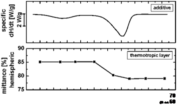 |
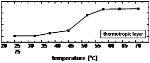
In Fig. 1 the hemispheric and diffuse transmittance of the thermotropic layer is plotted as a function of temperature. Furthermore the switching characteristic of the thermotropic layer is compared to the thermal transition of the additive used. In clear state the material exhibits an excellent hemispheric solar transmittance of 85% with a diffuse fraction of 40%. At a temperature of 45°C the hemispheric transmittance starts to decrease associated by an increase of the diffuse transmittance. This indicates that the layer undergoes a transition from a clear to a scattering state. In general the thermotropic layer shows a rapid and steep switching process within a temperature range of 15 K. Above the switching threshold the hemispheric transmittance decreases by 6% to a value 79%, with a diffuse fraction of 64%. The significant increase of the diffuse transmittance causes a loss of view-through behaviour. According to this switching range and switching temperatures the layer does not provide adequate overheating protection for a solar collector.
 50
50
Fig. 1. Thermogram of the additive (top) and hemispheric (middle) and diffuse solar transmittance (bottom) of
the thermotropic layer as a function of temperature.
The comparison of the thermotropic layers switching performance with the additives thermal transitions reveals a good correlation. At the onset of the additives melting peak between 45 and 50°C the hemispheric transmittance decreases and the diffuse transmittance increases significantly.
Subsequently the switching proceeds with the melting of the additive. The thermotropic layer reaches its final scattering state once the additive is in a fully melted state. Besides the melting peak of the additive an endothermic effect at lower temperatures (25-35°C) is observable. This peak can be attributed to a phase transition in the crystalline structure. This endothermic effect leads to a slight change of the solar transmittance. The excellent correlation shows that the switching temperature and process of the thermotropic layer can be tailored by selecting adequate additives.
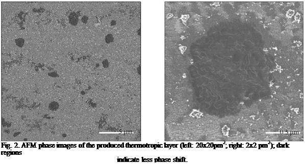
In Fig. 2 AFM phase images of the thermotropic material are depicted. Dark colours represent a smaller phase lag and bright colours a larger phase shift. According to this, the darker areas represent the softer additive particles and the resin matrix appears bright. This is confirmed by the higher magnification of a dark area shown in the right image, which reveals a superstructure characteristic for the additive used. It is observable that the additive particle dimensions and thus scattering domain sizes range between 0.4 and 2.5 pm.
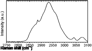
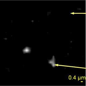
Figure 3 illustrates a map of the chemical constitution of the surface determined by Raman microscopy along with spectra in the wavenumber range between 2750 and 3100 cm-1. The two presented spectra are representative for the whole surface area. While the top right spectrum characterizes the resin the distinct peak at a wavenumber of 2883 cm-1 of the bottom right spectrum can be attributed to an asymmetric stretching vibration of CH2 groups of the additive. According to the spectra bright colours of the map represent the additive. Additive domain sizes of about 1 pm are detectable. Hence, Raman microscopy confirms the morphological features determined by AFM phase imaging. However, due to the limit lateral resolution of the Raman microscope the domains are less distinct than in the AFM phase image.
 |
 |
The particle size of the thermotropic layer between 0.4 and 2.5 pm is in good agreement with its moderate reduction of the hemispheric transmittance and the significant increase of the diffuse transmittance. For optimum back scattering efficiency domain diamteres between 200 and 400 nm are required [6]. Larger particles lead to increased diffuse scattering above the switching threshold. Thus to enhance the light shielding performance of the thermotropic layer a significant reduction of scattering domain size is required.
Fig. 3. Raman map (left: 20x20pm2) showing the distribution of additive on the layer surface together with
Raman spectra of a pure resin (top right) and a resin containing the additive (bottom right).
4. Summary and Conclusions
Within the present investigation a thermotropic resin was characterized as to light-shielding efficiency, switching temperature and switching performance. In the clear state the thermotropic layer showed a solar transmittance of 85%. Above the switching temperature of 45°C the hemispheric transmittance amounted to 79%. The diffuse transmittance increased significantly from 40% in the clear state to 64% in the scattering state. The increase of the diffuse transmittance along with the moderate change in hemispheric transmittance was found to be in good agreement with average additive particle dimensions and thus scattering domain sizes of 0.4 to 2.5 pm ascertained by AFM phase imaging and by Raman microscopy. Thus to enhance the film’s reflectance efficiency a significant reduction of scattering particle diameters is required. An excellent correlation between the thermotropic layers’ switching performance and the thermal transition of the additive was ascertained. This enables the production of thermotropic materials exhibiting tailor-made properties by selecting adequate additives.
References
[1] G. M. Wallner, K. Resch, R. Hausner, Solar Energy Materials and Solar Cells, 92 (2008) 614-620.
[2] K. Resch, G. M. Wallner (2007). In Proceedings of ISES SWC 2007, Beijing, China, pp. 541-545.
[3] K. Resch, G. M. Wallner, R. W. Lang, Macromolecular Symposia, 265 (2008) 49-60.
[4] K. Resch, G. M. Wallner (2008). Submitted to Solar Energy Materials and Solar Cells.
[5] R. E. Bird, R. L. Hulstrom. Solar Energy, 30 (1983) 563-573.
[6] P. Nitz, H. R. Wilson (2008). In Proceedings of 2nd Leobner Symposium Polymeric Solar Materials, Leoben, Austria, pp. XIn-1-XIn-6.
 |
Acknowledgements
Specialties (Drogenbos, BEL) and Sasol Germany GmbH (Hamburg, GER) for providing the materials.
The computed values of (i) ASTM and (ii) IOS grain size numbers (Gn and Gm), (iii) average grain
Area (iv) average grain diameter d, (vi) grain size distribution (or uniformity) (Gd) and porosity factor (PT) for the films (Table 1) show the followings for the different films.
Snl2 and MnBr2 Films: NA = Gn and Gm values are higher for MnBr2 than for Snl2 indicating that
MnBr2 contain more grains than Snl2, as explained in the section above. A and dvalues are larger for Snl2 than for MnBr2, indicating that Snl2 films have larger grains. L value is larger for MnBr2 than for Snl2 showing that MnBr2 films have more oblong grains, while Snl2 grains tend to be more roundish or circular. Gd for MnBr2 is larger than for Snl2 showing that Snl2 have more uniform grains than MnBr2. PT for Snl2 is larger than that for MnBr2 indicating that Snl2 is more porous than MnBr2. These also explain why MnBr2 tends to have is higher absorption of UV radiation that Snl2. This is because when a film with tinny grains is porous, there is little or no absorption of UV — VIS radiation by the grains, hence the radiation finds it easier to pass through as in Snl2. But when a tinny grained film is dense, UV absorption tends to be higher with a substantial NIR reflection as well. The only wavelength of transmission for such films would therefore be the visible radiation as shown in fig 1.
PbBr2 and Pbl2 films: Gn and Gm are about the same for both films although they are a little bit
higher for Pbl2 than for PbBr2 indicating somewhat more grains for Pbl2. A and d are a bit larger for PbBr2 than Pbl2 showing somewhat larger grains for PbBr2. Lv is higher for PbI2 then for PbBr2 indicating that PbI2 have more oblong grains than PbBr2. Gd PbBr2 is larger than Pbl2 showing that Pbl2 grains are more evenly distributed than PbBr2. PT is higher for PbBr2 than for Pbl2 showing that PbBr2 is more porous than Pbl2. Generally, these films are highly porous, hence they will transmit highly in the UV but have improved late visible and infrared reflection from about a cut off of 450 to 550mn.
Ag2S and PbS films:Gn and Gm are higher for Ag22 than PbS, hence Ag22 have more grains than
PbS. A and d for PbS are higher than those for Ag22, indicating that PbS grains are larger than Ag2s grains. Lv for PbS is higher indicating that their grains are more oblong than those of Ag2S Gd for PbS is higher showing that PbS is less evenly distributed. RT is higher for Ag2S showing that it is more porous. The very large nature of the grains of these films combines with moderate porosity and high void make them highly absorbing in the UV and Visible but highly transmitting in the Near Infrared. High voids and vacancies through out the film would allow infrared radiation to go through easily whereas the visible ultraviolet radiations would be easily intercepted (absorbed) by the large grains.
3. Conclusion
From the above, film microstructures (i. e. the geometric exterior and grain size parameters) were observed to be related to the spectral characteristics of films [2]. Films with smaller grains, which tend towards continuous, show high UV absorption, NIR reflection and Visible transmission as in Snl2 and MnBr2 and Pbl2 films. Films with moderate grains, which are more widely and uniformly spaced show high UV-VIS transmission and improved NIR reflection like the PbBr2 and Pbl2 films. On the other hand, films with larger grains which tend towards continuous absorb UV-VIS radiation completely but transmit in the infrared region as in the Ag2S and PbS films [2].
The Snl2 and MnBr2 films can be used as window coatings for warm climates to prevent UV and IR radiation from entering buildings but allow only visible radiations for “day lighting” [2, 15-16]. Hence natural air conditioning can be created by using these films.
Therefore Snl2 and MnBr2 films can be used as visible transparent window coating. (VTWC) otherwise known as “Cooling Windows” to block and prevent UV (high energy) AND IR (high heat) radiations from entering but allow visible radiation only into the buildings if the glass doors and windows of such buildings are coated with these films. This can create natural air-conditioning (cooling) of the building interior [12, 15, 16].
Pbl2, PbBr2, PbS and Ag2S films can be used to split the solar spectrum into two broad bands, which can be used for different applications. The lead halide films, which favour UV-VIS transmission and IR reflection can be used to reflect infrared radiation and prevent it from getting to the surface of photovoltaic cells if the films are used to coat solar cell surfaces [2, 15-16]. This is because solar cells work better in the absence of infrared radiation. Such films are called Visibly transmitting spectral splitters (VTSS) and behave like “Cold Mirror”. On the other hand, PbS and Ag2S films can be used to coat glasses, which can be used to absorb UV-VIS radiation, while NIR radiation is transmitted. These glass systems called infrared transmitting spectral splitters (IRTSS) and behave like “Heat or Dark Mirrors” they can be used to regulate solar and thermal energy for Conventional Green House Agriculture (CGHA) and for Control Environmental Agriculture
(CEA), in which various parameters that affect yield and quality of crops are optimized and
regulated [15, 18-20].
Reather, H., 1976. Structure of Thin Films. In: Physics of Non-Metallic Thin Films, Eds C. H. S. Dupuy., A Cachard, Plenum Press, New York. 123-140.
Okujagu, C. U., 1992. Growth and Characterization of Thin Film Selective Surfaces and their Applications. Ph. D Thesis, Department of Physics and Astronomy, University of Nigeria, Nsukka.
Sirimane, P. M., Tributsch, H., 2007. Generation of Inhomogeneous Photo Current in Solid State Ti O2/Dye/CuI Cells and Effect of Ligands Attached to Surfactant on Morphology of CuI Films. Solar Energy 81 (4) 535-539.
Vander Voort, G. F., 1984. Grain Size Measurement. In: Practice and Appl. of Quantitative Metallography, Symposium Proc. ASTM, STPB 39, Philadelpha, Eds J. L. Mc Call., J. H. Steel, Jr. 85-131.
ASTM 1984. Committee E-4 on Metallography. Standard Methods for Determining Average Grain Size Designation: E 112-84 (Pub. August), 116-149.
Papini, M., 1986. Chemical, Structural and Optical Characterization of Ni-P Chemical Conversion Coatings for Photo-Thermal Absorption of Solar Energy. Solar Energy Materials 13, 233-265.
Hillard, J. E 1962. Grain Size Estimation. Report No 62 Rl-1133, General Electric Laboratory, Schenectady,
N. Y; December.
ASTM 1982 Standard Methods for Estimating the average Grain Size of Metals (E 112-82). Annual Books of Standards, Part 11, American Society for Testing and Materials.
Okujagu, C. U., Okeke, C. E., 1997. Growth Characteristics of Chemically Deposited Halide Thin Films. Nigerian Journal of Renewable Energy 5(1&2) 125-130.
Okujagu, C. U., Okeke, C. E., 1998. Growth Characterization of some Spectrally Selective Halide and Chalcogenide Thin Films, Nigerian Journal of Renewable Energy. 6 (1&2) 56-61.
Kokate, A. V., Suryavanski, U. B. Bhosale, C. H., 2006. Structural Compositional and Optical Properties of Electrochromically Depsited Stoichiometric Cdse Films from Non-Acqieous Bath. Solar Energy 80 (2) 156-160.
Razykov, T. M., Kouchkarov, K. M., 2006. Influence of Growth Rate on the Nanocruystallinity of II-VI Films in Chemical Vapour Deposition. Solar Energy 80 (2) 182-184.
Okujagu, C. U., 1999. Thin Film Technology for Energy Supply and Regulation in Nigeria. Journal of Applied Science and Environmental Management 3, 5-9.
Murali, K. R., 2008. Properties of Brush Plated Cdx ZnJ-X Te Thin Films. Solar Energy 82 (3) 220-225.
Okujagu, C. U., Okeke, C. E., 2000. Prospects of Spectral Splitting Thin Films in the Development of Photothermal, Photovoltaic and Green House Technologies. Nigerian Journal of Renewable Energy 8 (1&2) 24-31.
Okujagu, C. U., Okeke, C. E., 1997. Effects of Materials Properties on the Transmission of Selective Transmitting Thin Films. Nigerian Journal of Physics, 9, 50-66.
Sethi, V. P., Sherme, S. K., 2007. Thermal Modeling of Green House Integrated to an Acquifer Coupled cavity Flow Heat Exchanger. Solar Energy 8 (6) 723-741.
Sethi, V. P., Sharma, S. K., 2007. Survey of Cooling Technologies for World Wide Green House Applications. Solar Energy 81 (12) 1447-1459.
Davies, P. A., 2005. A Solar Cooling System for Green House Food Production in Hot Climate. Solar Energy 79, (6) 661-668.
Kumar, A., Twari, G. N., 2006. Thermal Modeling of a Natural Convection Green House Drying System for Jaggrey: An Experimental Validation. Solar Energy 80 (9) 1135-1144.
Fig. 15 shows boiler heating used to DHW. The annual DHW heating of Cases A, B and Case C were 3.842kWh/year and 1.467kWh/year, respectively. The DHW heating of Case C decreased to about 40% as compared with Cases A and B by solar energy used to DHW supply.
3.2. Annual heating and cooling load and boiler heating used to DHW
 |
 |
Fig. 16 shows annual cooling and heating load and boiler heating used to DHW. Annual heating and cooling load and boiler heating used to DHW of Case A, B and C were 7.09MWh/year, 6.81MWh/year and 3.96MWh/year, respectively. Annual heating and cooling load and boiler heating used to DHW of Case C decreased to about 44% as compared with Case A.
Case A Case B Case C Case C
No adjacent houses Adjacent houses Adjacent houses and Solar energy used to
active solar heating floor heating
 Fig 16. Annual cooling, heating and hot water supply
4. Conclusion
The total effect of solar space heating with active and passive ways were examined using the detailed system simulation with a generalized simulation tool (EESLISM ver6) developed by the authors.
The annual heating load for the adjacent houses Case B increased by 1.37 times compared with the no adjacent houses Case A. However, the annual heating loads for the adjacent houses and active solar heating system Case C were almost equal to those of Case A. In the dense housing area, heating by active solar space heating system is effective.
The annual cooling loads for the adjacent houses Cases B and C were about 55% compared with the no adjacent houses Case A. This result is mainly the influence by the difference of incident solar radiations of the eastern and western outside surfaces.
Acknowledgment
This study was supported by the Grant-in-Aid for Scientific Research (C) (19560598), The authors would like to express their sincere thanks to the support.
References
[1] Higuchi, Togashi, Udagawa, Tanabe(2008). Continuous development and future perspective of EESLISM, AIJ, 1119 — 1122 . (in Japanese)
[2] Higuchi, Udagawa(2007) : Effects of trees on the room temperature and heat load of residential building, building simulation 2007 in China Beijing
[3] Higuchi, Udagawa, Sato, Kimura (2007): Study on effect of housing placement on annual space heating and cooling loads of the house — Study on heat load simulation considering thermal effects of external environment Part2 , J. Environ. Eng., AIJ, No.612, 31-38 (in Japanese)
[4] Higuchi, Udagawa, Sato, Kimura (2001): Calculation model of solar radiation and long wave radiation for external environment — Study on heat load simulation considering thermal effects of external environment Part1, J. Archit. Plann. Environ. Eng., AIJ, No.544, 9-15 (in Japanese)
[5] Architectural Institute of Japan, Expended AMeDAS Weather Data, 2005. (in Japanese)
A. Gonzalez1, M. Izquierdo1* and A. Moreno2
1 Instituto de Ciencias de la Construction Eduardo Torroja (IETCC)-CSIC
Serrano Galvache 4, 28033 Madrid, Spain
2 Universidad Carlos III, Madrid, Spain
* Corresponding Author, mizquierdo@ietcc. csic. es
A thermodynamic model of a direct expansion solar assisted heat pump (DX-SAHP) was developed in order to simulate its behaviour in space heating applications. In this study, four different configurations of DX-SAHP were simulated using meteorological data from Madrid. The predicted results for this region indicate that long-term performance of the system ranges from 2.08 and 2.41 and that any of the studied configurations may be considered as an available solution to saving energy and CO2 emissions. Simulation results also indicate that in working with underfloor heating and R134a as refrigerant, DX-SAHP systems are more efficient. On the other hand, the proposed model permits us to know the number of panels needed to install in a specific space heating application.
Keywords: solar assisted heat pump, direct expansion, residential heating, energy saving
1. Introduction
Mitigation of global warming involves taking actions to reduce greenhouse gas emissions associated to residential buildings. Thus, it is essential to improve energy efficiency in buildings, what firstly means decreasing energy consumption and secondly substituting fossil energy sources for renewable ones. In a few words, it is necessary to research on efficient and environmentally friendly systems for heating and air conditioning applications in buildings. In this regard, both heat pumps and solar energy systems are receiving much attention. On the one hand, heat pumps may save energy in heating applications because they augment input energy with heat collected from the environment; as well, they may provide summer cooling in a rather efficient way. In spite of these advantages, viability of heat pumps has been questioned because of several aspects, for example, its reduced capacity and efficiency for low ambient temperatures. On the other hand, solar energy systems present not only some attractive advantages but also a series of problems: solar energy is known to be non-polluting and inexhaustible, but also intermittent and dispersed. Then, one can think about combining heat pumps and solar energy systems to reduce the disadvantages that each one has in operating separately. In this way, several researches have proposed the solar-assisted heat pump (SAHP) as an attractive solution for saving energy in residential applications.
From the review of existing literature, one extracts that SAHP can be operated in two basic configurations. In conventional one, a solar collector and a heat pump are integrated trough an intermediate closed loop, from the collector to the thermal storage. The circulating fluid (usually water or air) transfers solar energy to refrigerant in heat pump [6, 9, 10]. In the second configuration, so-called direct expansion solar-assisted heat pump (DX-SAHP), the collector and
evaporator are combined into one unit, where the refrigerant from the condenser is expanded and gets evaporated by incident solar energy and/or ambient air energy [3, 5, 7, 8, 11]. According to Chatuverdi [3], the DX-SAHP presents several advantages over the conventional SAHP. First, this system offers a superior thermodynamic performance since a higher heat transfer occurs when refrigerant is boiling in collector/evaporator. Next, system cost is lower due to elimination of the evaporator and the intermediate heat exchanger used in conventional SAHP. Finally, collector life is longer because the use of a refrigerant as working fluid avoids freezing and corrosion problems associated with water collectors.
Although several researches concerning DX-SAHP have been performed for last years, not many of them discuss space heating applications of the system, nor make an estimation of total energy absorbed by collectors during heating season. On the contrary, most of these studies are focused on water heating applications trying to predict work conditions which make the system COP highest. The present work intends to develop a simplified model which enables to simulate the dynamic behaviour of a DX-SAHP in space heating applications. This simulation is permitting us to estimate, for example, the thermal performance of the system, the heat absorbed by collectors or the electrical energy consumed by the system. In knowing the energy consumed, associated greenhouse gas emissions will be estimated and compared with those ones corresponding to other conventional space heating systems: natural gas and gasoil boilers. Meteorological data used in simulation are from a weather station located in Madrid, which represents one of the most populated regions in Spain. Finally, the study considers the use of two different refrigerants, R134a and R407C, and two heating systems, fan coil and underfloor heating.
 |
A different approach for low concentration photovoltaics has been investigated, combining effectively stationary symmetric or asymmetric CPC reflectors [25] with PV absorber strips and thermal absorbers. A first system is the stationary CPC reflectors with flat bifacial absorber, where two PV strips can track the converged solar radiation on each absorber side and absorb the concentrated solar radiation to convert it to electricity (Fig. 6a). The non-absorbed beam solar radiation and the diffuse solar radiation are absorbed by the flat bifacial thermal absorber and can be taken away to a thermal storage (or directly to the use) by the circulation of a heat removal fluid. The PV strips operate in a similar way as in the Fresnel lens device. A second CPC type concentrating photovoltaics is the asymmetric CPC reflector (Fig. 6, b and c) where the thermal part is a usual type of thermal collector and the PV strip is moving infront of the thermal absorber tracking the converged radiation. In this system the parabola axis can be directed to higher altitude of sun (summer, Fig. 6b). An alternative design can be also realised (Fig. 6c) where the parabola axis is directed to the lower sun altitude (winter). In the last two devices, the non-absorbed converged solar radiation and the diffuse solar radiation are absorbed by the well thermally insulated flat absorber and result to the heating of the circulating liquid.
For typical energy efficient office buildings the following energy concepts are studied and the role of the building envelope in each of the concepts is described with special focus on:
• Passive solar design (Thermal insulation of the building envelope, windows/glazing type, size and orientation)
• Climate adapted design (Air tightness of the building envelope, efficiency of heat recovery system)
• Active solar design (BIPV, Solar thermal collector)
The total energy consumption is simulated for four different construction standards and the results are compared using dynamic building simulation software SQIAC [2]. First, the Old Norwegian standard from 1997 was taken and the resulting energy savings of special construction details is shown. Then, the resulting energy savings of the New Norwegian regulations (TEK 2007) are calculated. After that, the passive house standard (PH) is applied to a typical office building and the resulting energy savings are shown. Finally, possibilities for on-site renewable energy production to reach zero net energy buildings are explored.
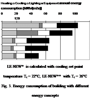
In this respect it was interesting to estimate the uncertainty in the input parameters. A sensitivity analysis of eight different design parameters for an office building has been carried out and detailed results have been reported [6,7]. The technologies suggested for upgrading the buildings from one category to another were determined by sensitivity analysis and were summarized. The New TEK07 tightens the requirements for U-values of the building envelope and air tightness and requires setting the cooling set point temperature to 22°C which increases the cooling energy consumption. Therefore, two low energy categories were simulated; one with set point temperature set to 22°C, the other with set point temperature set to 26°C.
|
Table 1. Geometry of buildings
|
The building geometry for the buildings PH+ concept was changed in order to identify the building geometry with the minimum energy consumption and maximum roof and facade area for energy production. Electricity production from PV cells (with overall efficiency of 11%) and thermal energy production from solar thermal collectors (with overall efficiency of 56%) were considered. Annual solar flux on surfaces of the building were determined from SCIAQ [2].
The geometry of the different cases is described in Table 1. All building models have the same total heated floor area of 6299m2 while the building height has been altered between 2 and 5 floors in order to study the sensitivity of the A/V ratio.
2. Results
2.1. Sensitivity of design parameter
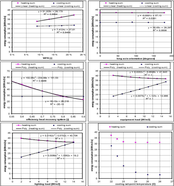
In order to identify the uncertainty of design input parameters an OAT sensitivity analysis was done for TEK07 building standard [9]. Figure 2 shows the scatter plots for four design parameters together with their regression curves. They show that most design parameters are sensitive to changes except the orientation of the building. It can further be seen that the parameters have different sensitivity towards heating and cooling energy consumption.
• While a decrease in air leakage results in a reduction in heating energy consumption it increases (to a smaller degree) the energy consumption for cooling.
• A decrease of the U-value of the windows results in a reduction of heating but an increase in cooling energy consumption.
• A decrease of the window-to-floor-ratio (WFR) results in a reduction of heating and cooling energy consumption.
• An increase of the efficiency of heat recovery system results in a reduction of heating energy consumption.
• A decrease of the equipment load results in an increase of heating but a reduction in cooling energy consumption.
• A decrease of the lighting load results in an increase of heating but a reduction in cooling energy consumption.
2.2.
An increase of the cooling set point temperature results in a reduction of heating and cooling energy consumption
 |
Different energy concepts have been developed that apply results from the sensitivity analysis in order to reduce total energy consumption of the building. They are described as follows:
The energy concept of LE-OLD was based on the following measures:
• Increase in air tightness to n50 = 1.5 ach (from n50 = 4.29 ach)
• Reduction of windows area to WFR = 0.131 (from WFR = 0.1745)
• Installation of an effective external shading device with Fs = 0.5 (compared to no shading device with Fs = 1)
• Introduction of a heating set back temperature of Th = 20°C
• Installation of efficient lighting and equipment with ql = qe = 10 W/m2
The energy concept of LE-NEW was based on TEK07 with the following measures:
• Increase in air tightness to n50 = 1 ach (from n50 = 1.5 ach)
• Reduction of windows area to WFR = 0.131 (from WFR = 0.1745)
• Increase in efficiency of heat recovery system to ny = 0.85 (from ny = 0.7)
The energy concept of passive house was based TEK07 with the following measures:
• Increase in air tightness to n50 = 0.6 ach (from n50 = 1.5 ach)
• Increase in efficiency of heat recovery system to ny = 0.85 (from ny = 0.7)
The energy concept of PH+ was based on passive house with the following measures:
• Reduced installed power of lighting by reasonable placing of lights
• Control based on time, motion sensors, and daylight sensors
• In the calculation model these measures have been implemented by reducing the lighting load to ql = 6 W/m2 (from ql = 8 W/m2)
• Use of LCD-flat screens. laptops and others (printers. scanners. copy machines) with high energy efficiency led to qe = 5 W/m2 (from qe = 11 W/m2)
Figure 3 gives the results of calculations for an office building. It can be seen that heating energy consumption can be significantly reduced. The New low-energy concept is very sensitive to cooling set point temperature. For LE-NEW with a cooling set point temperature of 22°C there is more energy consumed for cooling than for heating. LE-NEW with a cooling set point temperature of 26°C there is not a large difference to the passive house concept (PH). The PH+ concept exceeds the allowed maximum of 15 kWh/(m2a). Improvements could be reached by applying windows with a lower U-value (see sensitivity analysis in previous section).
 LE-OLD LE-NEW*
LE-NEW**
Passive house (PH)
Passive house (PH+)