Как выбрать гостиницу для кошек
14 декабря, 2021
1.1. The ejector characteristic curve
The ejector works according to a characteristic curve. For given Pe and Pg, the ejector works at on — design conditions as long as the condenser pressure Pc is lower than a critical backpressure Pc*, such as the chocking in a simple nozzle. This on-design working is characterised by a constant and
maximal entrainment ratio U = m tm and coefficient of performance COP =—————- Q——— .
gr v Q + Q + Q
g sup pump
Pc obviously increases with the external temperature. When Pc>Pc*, the ejector performances drop noticeably and the ejector works at off-design conditions. It is worth noting that U and Pc* are strongly dependent on Pe and Pg. Pc* is higher for high Pe and Pg. U is higher for high Pe and low Pg. It is important to highlight that the pseudo-1D model used for the ejector in the rating model cannot predict the off-design conditions, that is when Pc>Pc*. Only the optimal working point (maximal U, Pc*) obtained for given pressures and temperatures conditions at the ejector inlets is computed.
The aim of the rating model is to evaluate and predict the variations of performances for a given EACS installation, when this system is submitted to different external thermal and/or operating conditions. In the proposed experimental stand, the water will be used as coolant for the condenser, generator and evaporator. Each inlet water temperature and mass flow rate is hence given. All plate heat exchangers and ejector dimensions are given as well. The design was previously computed with the sizing module which gives the best design for the desired operating condition: in the design process, the cooling capacity Qe and a heat capacity Qg were of 5 and 12 kW respectively. The saturated temperatures Tgsat, Tesat and Tcsat were 90°C, 10°C and 40°C respectively. All the inputs of the rating model are reported in the table 1.
|
Ejector dimension [mm] |
Exchange surface A [m2]/plates number N |
|
Dt D1′ D2′ Dd Ddif 2.2 3.2 6.9 4.5 6.3 |
Ag Ac Ae Asup Ng Nc Ne Nsup 1.26 2.48 2.59 1.14 21 42 29 19 |
|
Table 1. Inputs of the rating model. See figures 1 and 2 for nomenclature. |
|
Mass flow rate [kg/s] |
Temperature [°C] |
|
mgw mcw rhew a(%) 0.233 0.792 0.199 0.130 |
T T T eiw ciw supiw 18 32 100 |
Two additional heat exchangers, depicted in fig. 1, were envisaged to improve the whole EACS performances:
— A subcooler, to cool mer before its expansion in the throttling valve, with the refrigerant leaving
the low pressure separator (after evaporator). A previous study permitted to deduce the most judicious exchange surface of the subcooler, namely 2m2 [5].
— A regulator: A part в ofmew, initially devoted to create the cooling effect is extracted from the
evaporator to cool rhcw in the condenser. The use of such a heat exchanger aims at reducing Pc
until it reaches Pc*, allowing the ejector to work-back at on-design conditions. It is worth noting that even if a lower cooling power is available, this loss of cooling is obviously smaller than the loss that would occur with the steep drop of U beyond Pc* (cf. fig. 3a, off design prediction). A succession of on/off states is moreover avoided with the regulator.
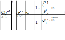
A pseudo-ID model is used to compute the thermodynamic properties within the ejector. The energy and momentum equations of conservation are applied to large control volumes in the ejector. The calculation procedure was described for the sizing module (Hemidi et al. [5]). From the geometry and thermodynamic conditions at the ejector inlets, U, Pc*, are computed. mgr is
determined by the well known isentropic relations. mer is hence deduced.
![]()
![]()
![]() (1)
(1)
*
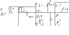
Pc* is computed iteratively:
 |
At each main heat exchanger, the pressure depends on the geometrical configuration, the temperatures, the mass flow rates and the equilibrium between the heat exchanger and the separator. At the separators, the refrigerant is at saturated state. If the heat exchanger is undersized, the refrigerant is at two phase state. To compute the saturated pressure for each heat exchanger, the following methodology is used:
— Two pressure thresholds are determined:
• For a given surface of a heat exchanger, only one pressure corresponds to the case of a total evaporation/condensation. The refrigerant is on the saturated curve at the exit of the heat exchanger, any recirculation occurs. This pressure is determined by iteration until the computed surface corresponds to the actually available surface;
• The second threshold is the pressure for which the heat exchanger efficiency is 1. This matches to a zero pinch and it is obviously never the case.
The real pressure is estimated between both of these thresholds:
|
|||
|
|
||

The parameter Ф is computed iteratively until reaching a pressure for which the surface required to do a total phase change is slightly higher than the actual surface. However, the thresholds difference remains small.
— Once the real pressure is known, iterations on the vapor quality xv at the heat exchanger exit are made until the computed and actual surfaces are equal. The refrigerant state at the exit of the heat exchanger is deduced, as well as the transferred power Q.
To compute the surface required for the heat transfer, the s-NTU method is applied. The following procedure is used:
— Calculation of the global heat transfer coefficient Hoverall:
|
|
|
|
|
|
|
|
|
|

The heat transfer coefficients Hr and Hw are predicted with different correlations: Dittus and Boelter, Nu = 4.36 or interpolation according to Reynolds number for the single-phase flows, Chen correlation for ebullition in the generator and the evaporator, Shah correlation for condensation. Note that single-phase (superheat, subcooling) and two-phase flows can coexist. This methodology is hence applied separately for the single and two-phase part.
— Calculation of the efficiency s:
![]()
![]() _____________ Qactual__________
_____________ Qactual__________
(m ■ Cp) . x T — T
mm гг iw
where (m ■ Cp)min = min(m wCpw, mrCpr)
— Calculation of the Number of Transfer Unit NTU: ( m ■ Cp)
r _____ _V____ 1 /min
(гіг ■ Cp)
max
*
![]() NTU = 1 ln 1 — R
NTU = 1 ln 1 — R
The exchange surface A is deduced by:
![]() NTU •(m • Cp) .
NTU •(m • Cp) .
A =______ 1___ _^mm
H
overall
2.1. Influence study of the external temperature Tciw
As seen before, the climatic conditions have a noticeable effect on the ejector systems. Hence, this investigation presents the performances variations of the EACS with Tciw (which reflects the external temperature variation), with or without the subcooler and for two values of a.
The figure 3a and 3b allow comparing the COP when the subcooler is used or not. A first remark is that the optimal working zone, characterized by P = 0, is reduced of about 1°C when the subcooler is used (critical point at Tciw = 28.4°C against 29.5°C without subcooler). In fact, the rise of Tej2 leads to a decrease of Pc*. In this zone of optimal working, the COP and Qe are better with 6.7% and 6.6% of increase respectively for Tciw=28.4°C. But the figure 3b shows that U is lower when the subcooler is used. The thermodynamic conditions remaining constant for the high pressure side, mgr is constant. But the rise of Tej2 involves the drop of U and thus of mer. In spite of that, the
increase of enthalpy difference Ahe is more noticeable, so performances are improved when the subcooler is used. This proves that seeking a best ejector entrainment ratio does not guarantee the best cycle operation, and that the overall cycle has to be taken into consideration for a performance study of an EACS. When Pc is greater than Pc*, the EACS is at off-design. The regulator is hence requested, and a part P of mew is used to reduce Pc under Pc*. p is all the higher as Pc increases and the lower are Qe and COP. Moreover, by comparing the COP obtained with and without the use of the subcooler when Pc is beyond Pc*, an important observation is that the subcooler has a harmful effect on performances. For instance, for Tciw = 29.4°C, COP = 0.41 without subcooler, and COP = 0.21 when the subcooler is used. It is concluded that as long as P = 0, the subcooler have to be used to improve the EACS performances. But when p > 0, the subcooler becomes unfavorable. A bypass of this heat exchanger is required from this moment to optimize the EACS working.
|
■ ■ ■ … |
Q, without subcooler e Q, with subcooler e |
|
■+++++~v ‘……………………………………………………………. : ++*++ ‘ ■ ++ 1 і ++ і і і |
U, without subcooler U, with subcooler |
|
***x 1 |
|
|
x ‘ 1 |
■ |
|
b) x |
|
0.56 0.55 0.54 0.53 0.52 0.51 0.5 0.49 0.48 0.47 |
|
4 |
|
22 |
|
24 |
|
26 |
|
28 |
|
30 |
|
32 |
|
34 |
|
T. [°C] ciw |
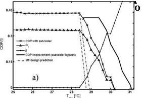 |
Figure 3: a) COP, p and Qe vs. Tciw, with and without the subcooler, for a = 0.13.
b) Qe and U vs Tciw with and without the subcooler, for a = 0.13.
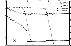
For a given a, the figures 4a and 4b show that the COP and Qe are relatively constant until a certain value of Tciw, and then drop. In fact, Pc increases with Tciw. It is seen that Pg rises with Tciw in a first time and becomes constant after. Thus U decreases, Pc* increases because of Pg, but less noticeably than Pc, such that Pc becomes higher than Pc*. The regulator starts working, and Qe and COP drop.
When a decreases, it is obvious that a lower superheat is performed but Pg is higher. Hence Pc* is higher (Pe remains constant) and the optimal working zone is higher. It is observed as well that COP is slightly higher as long as Pc remains lower than Pc* (fig.4a), despite the fact that Pg is higher for low a. Actually, the rise of mgr resulting from Pg increase is balanced with the decrease of Ahg that occurs near the critical point of propane. For low a , Qg is only slightly higher.
 |
 |
Furthermore, although U is lower (higher Pg, Pe constant), a better Qe is obtained, and gets the better of Qg (fig.4b). When p > 0, a low a is judicious too (fig. 4a): for instance, for Tciw = 26.8°C, the EACS works at optimal conditions for a = 0.13 (COP = 0.41), but the COP drops when a rises (COP = 0.05 for a = 0.6).
Figure 4: a) COP vs. Tciw for different a, without the subcooler.
b) Qe and U vs Tciw for different a, without the subcooler.
The most important characteristic of a chiller is its coefficient of performance (COP) though it only gives a proportion for the current performance of the machine and does not show its overall performance. Therefore it is better to use the monthly or annually average to rate the efficiency. These values can be calculated from the total heat consumption and the total cold generation of the absorption chiller.
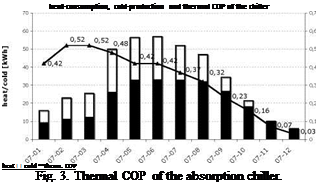
For the year 2007 monthly COP values were calculated from the cold generation and the heat consumption of the machine (see fig. 3). The average thermal COP in 2007 was 0.37.
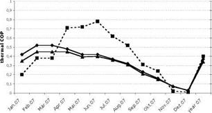
The absorption chiller requires, besides the thermal power demand, also electric energy for operation. In the case of the installed machine this energy is mainly used to supply three pumps, two pumps for the solvent circuit and one pump for the refrigerant medium circuit. The electric connected load of the machine is 3.4 kW, according to the technical specifications. The monitoring results show a permanent electric load of 3.0 kW, regardless of the cold production level. Inclusion of this electric energy consumption into a total COP results in the diagram in figure 4.
The total electric COP in 2007 was 4.0 and the combined thermal and electric total COP was 0.34. Including the parasitic energy used for re-cooling the COP even drops to 0.33.
Heat supply of the absorption chiller, according to the energy concept, aims primarily at solar energy. However, the chiller was operated permanently, not taking into account whether there were solar gains or not. The cold consumption of the building in 2007 was significantly higher than planned. The reason was the higher internal load provided by lighting. Hence the wood pellet boilers provided 81% of the heat for the absorption chiller, compared to 19% solar contribution.
|
|
|
|
|
|
|
The primary energy consumption per produced kilowatt-hour cold can be calculated from the consumption of the different energy sources (wood, electricity) for the heat generation and the COP of the absorption chiller:
|
In summary, the results of the monitoring of the absorption chiller are rather unfavorable. Both, primary energy balance and carbon dioxide emissions are significantly worse compared to the compression chiller, which was also monitored. The main reason for the bad results is almost solely the high parasitic energy of the absorption chiller itself. In the following the reasons for the bad results will be qualified.
This study comprises 172 schools. The schools can be divided in two groups depending on the building type:
• Pavilion (P): schools built after the 70’s typically composed of five two-story pavilions with twelve classrooms each
• Non-Pavilion (NP): larger, four to five story buildings with sloped roofs, built before the 70’s
This distinction will allow us to define, for each group a typical roof area by analysing a representative subset, containing 78 schools. The distribution between the two types is shown in Figure 1.
|
Figure 1. Distribution by type of school. On the left the 172 schools full set, on right the 78 subset.
|
The analysis was carried out in several phases (described ahead):
• Estimation of the suitable roof area
• Estimation of the PV area
• Implementation costs of the PV system
• PV electricity production and emission of CO2
• Payback of the PV system
2.1. Solar filters:
Solar filters are glazing systems what are single and multilayer oxide films which have high reflectance for near infrared radiation (NIR) and high transmittance for visible (VIS) light. These properties would contribute to low heat gain and undiminimished luminosity inside the building respectively. Some example of such films include: Sns — Cu2s, Sn3-Al/Al, Sn O2, Cu2 O, Bi2 O3, In2 O3, Fe2 O3, Fe O, etc [59-60].
2.2. Selective thin films:
Studies in electrochemical and optical properties of materials show that there are some metal halide and halogenate materials which are capable of modulating the transmission- reflection/scattering capabilities of pure window glasses with respect to wavelength, causing the glazing system to achieve variable transmission modes depending on the indoor needs of the buildings [62-64]. Such films can also act as photo-optical or solar filters. It can as well be used to achieve cooling/heating of building interiors, while at the same time able to deliver acceptable daylighting level into the building. This work examines some of these types of films with a view to finding their optical performance and the optical parameters that are important in this application.
In the intermediate periods (from +5°C to +22°C) external air circulates inside the inter-facade void. With an adequate speed of air flows, this circulation can be natural (the so-called ‘stack effect’). Air temperature between the two walls of the facade can take on intermediate values — higher than the external and lower than the internal one, which is advantageous for the comfort within the building. The opening of windows doesn’t lead to a significant cooling of the rooms. The difference between air temperature in the rooms and the temperature of the external wall is also decreasing, which is a positive phenomenon. Both of these are of particular importance for office buildings, where due to lighting conditions windows are most likely to be located next to work sites.
In winter, as in the intermediate seasons, the inter-facade void enjoys higher temperature than the external one, especially in facades exposed to the sun, which prevents the cold air from penetrating inside through opened windows and increases the temperature of the internal facade wall.
On the basis of the Basic Survey Electricity Consumption of Small Users [4] a list was composed of electrical appliances in a typical Dutch household. In this survey the degree of penetration, being the percentage of households that owns a particular appliance is also listed. In the present list, common appliances (with penetration > 50%) are assumed to be present, while less common appliances (with penetration < 50%) are left off the list. So we did not examine a household with 60% of tumble dryer and 2% of Jacuzzi hot tub. The resulting list is shown in table 1.
|
Table 1. Appliances and their electricity consumption in a Dutch household after two steps to save energy.
|
The electricity consumption of the remaining appliances adds up to 3670 kWh/a, which is somewhat higher than the average electricity consumption of the Dutch dwelling (3350 kWh/a). How can we reduce this electricity consumption? A number of steps are discussed below.
Step 1: Elimination of standby electricity
In an average household, electricity consumption of standby modus makes up approx. 10% of the total consumption, which can be significantly reduced by application of so called ‘stand-by killers’. Different types of stand-by killers are available on the market. However, a more structural approach on the level of building related measures would entail the implementation of a series of wall outlets of a different colour (e. g. green) that can be switched off during the night or in absence of the occupants.
By eliminating all standby electricity the annual electricity consumption of the appliances on our list can be reduced by approx. 400 kWh/a (11%). This is perhaps an optimistic figure to achieve in practice as not all appliances lend themselves to standby killers (in particular those with a clock or a timer). Also some appliances’ standby consumption will only be reduced during the night.
Step 2: Replacement of appliances by the most energy efficient variant (A-label)
This step shows the potential of reducing electricity consumption with the state of the art technology. Table 1 shows that the largest gains in terms of kWh/a are achieved by application of low-energy light bulbs and replacing the refrigerator and the freezer with an A-label combined refrigerator-freezer.
With these and a number of other small replacements, the average Dutch tenant can save another 1016 kWh/a (28%).
Step 3: Low energy or renewable energy appliances
When considering the appliances remaining after step 2, a number of these require heat that is supplied in the form of electricity, such as the dishwasher or the washing machine. Offering heat from a boiler, a micro Combined Heat and Power plant (CHP) means that we avoid the heat losses in the electricity plant (50%) where the electricity is being generated. An even more desirable option is to use solar heat from a solar collector. This option is further discussed in chapter 3.2.2. Of course, care must be taken to reduce as much as possible any heat losses from the piping between the heat source and the dishwasher / washing machine.
Another major consumer of electricity in dwellings is the tumble dryer. Gas fired dryers are a good alternative or, more ambitiously, a drying room fed with waste heat from e. g. the refrigerator.
Further reductions are possible: research is being carried out on dishwashers that require no more than a single cup of water. Using the right soaps/enzymes, washing could be carried out at much lower temperatures, saving on the need for water heating. Drying at low temperatures, using a fan rather than a heater also lowers the heating demand.
Refrigeration is also a major electricity consumer. This could be done more efficiently using a cool room or cool cupboard in the house, that is efficiently cooled with ground heat exchangers or — in wintertime — by the evaporator side of the heat pump. Implementation of a top lid on the refrigerator avoids losses when opening the door. A carousel system can provide easy access to all wares stored.
A bonus for all these savings is a reduction in internal gains, which will reduce the risk of overheating of the dwelling during the summer.
It is doubtful whether we will achieve a factor of 4 in the reduction of domestic electricity consumption with the three steps described above. That means that in order to reach our target of 65 kWhp/m2a, additional measures will be necessary. This is the next step in the Kyoto Pyramid.
F. Linhart* and J.-L. Scartezzini
Solar Energy and Building Physics Laboratory (LESO-PB),
Ecole Polytechnique Federate de Lausanne (EPFL), 1015 Lausanne, Switzerland
* Corresponding Author, friedrich. linharl@epfl. ch
This article presents the results of a satisfaction assessment recently carried out amongst occupants of office rooms equipped with Anidolic Daylighting Systems. Questionnaires and complementary personal interviews were used to reveal which typical office lighting related problems are the most annoying to the occupants of the examined offices. The results show that occupant satisfaction within the examined offices is in general very good but that temporary daylight-overprovision and glare can sometimes cause considerable discomfort. The article concludes that window blind configuration, blind control as well as inappropriate handling by the occupants are the main reasons for the encountered problems and discusses different possibilities to deal with them.
Keywords: Daylighting, anidolic, office lighting, occupant satisfaction.
1. Introduction
Electric lighting often causes more than 30% of an office building’s electricity consumption [1]. The use of daylight (issued from the sun and the sky vault) for illumination purposes inside office buildings seems to be a very evident way to reduce a building’s electric lighting load. However, electricity savings do not come automatically with the installation of a sophisticated daylighting system. Lighting load reduction can only be ensured if the building’s occupants accept and agree to properly use this system. If, for example, building occupants override a sophisticated daylighting system by simply closing the window blinds and switching on artificial light in order to avoid glare related problems, then all effort was wasted. One main concern of architects and engineers should therefore be to develop daylighting systems that are easy to use and that allow the occupants to create a comfortable luminous environment within their office at all times.
The southern faqade of the LESO solar experimental building (LESO-SEB), located on the campus of the Swiss Federal Institute of Technology in Lausanne, is equipped with so-called Anidolic Daylighting Systems (ADS) [2]. These systems are based on the theory of non-imaging optics [3]: they transport a maximum of daylight from outside the building into its interior with minimal interreflections and minimal losses.
In order to get an insight into the occupants’ satisfaction and well-being when working within office rooms equipped with this type of faqade-integrated ADS, a detailed post-occupancy satisfaction assessment (based on questionnaires and personal interviews) has recently been carried out amongst 23 occupants of the LESO-SEB. The objective of this study was not only to find out whether occupants are satisfied with their office lighting or not, but also to identify weak spots in the lighting installation (e. g. within the ADS itself or the associated control system) and to find solutions for eliminating these weak spots.
This article first gives a detailed overview of ADS in general and the particular ADS installed within the LESO-SEB in Section 2. In Section 3, the results of the occupant satisfaction assessment are presented. Section 4 then outlines the lighting system’s identified weak spots and discusses possible ways to optimize occupant satisfaction within office rooms equipped with this type of ADS. A summarizing conclusion is given in Section 5.
The optical properties in the wavelength range from 300 to 2500 nm, affecting the solar energy gain of the glazing, are measured with a Varian Cary 5000 spectrometer, equipped with an integrating sphere and further custom-made accessories to enable the characterisation of lightscattering samples. All films show high transmission values both in the visible and the near infrared range, comparable to those of uncoated glass sheets as depicted in Fig.2a, thus proving to be appropriate candidates for the planned application. Light transmittance ranges from 0.90 to 0.92 and solar transmittance from 0.85 to 0.90, as calculated according to EN 410 [6].
The optical properties in middle and far infrared wavelength range (up to 50 pm), affecting the temperature-induced energy loss of the glazing, are measured with a Bruker Equinox 55 FTIR spectrometer. Both transmittance and reflectance measurements are carried out. Transmittance values mainly depend on the material thickness and vary from 0.06 for a 375 pm thick PMMA film to 0.25 for a 76 pm thick PET film, as calculated by weighting the measured spectra with the Planck’s black body radiation function at 283 K (Fig.2b). This partial infrared transparency, which distinguishes plastic films from glass panes, enhances the radiative heat transfer between inner and outer layers of the glazing and has therefore to be taken into account in combination with the emissivity while calculating the thermal insulation performance of the system.
 |
Additional optical measurements are performed to evaluate the photo degradation of films upon irradiation with UV-light in the wavelength range from 300 to 400 nm. Films suspended in a glass unit are exposed to variable UV-light intensities, depending on the UV-transmittance of the outer pane (0.80^0.85 for a white-glass uncoated pane, 0.05^0.55 for a common low-e coated pane, as calculated according to EN 410).
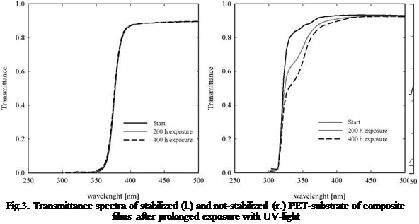
Accelerated indoor tests are carried out similar to EN ISO 4892 [7]. Both UV-stabilized and not — stabilized films, screened by differently UV-light transmittive glazings, are exposed to our solar simulator, which reproduces spectral distribution and intensity of natural sunlight (Air Mass 1.5) in the corresponding wavelength range. First results are evaluated after 400 hours exposure: not-
stabilized films, with the expected exception of PMMA, already show significant changes in their transmittance spectra if not completely screened from ultraviolet radiation, proving to be not suitable for the planned application. The effectiveness of the UV-protective coating used as stabiliser (Fig.3) has now to be investigated over a longer period by both laboratory and outdoor tests.
During ENERGYbase project time a comprehensive set of scientific support was done. Herewith, selected actvities and results are presented and following sections reports briefly on ENERGYbase design and system features, e. g. south faced facade, solar-assisted air-conditioning.
1.1 Use of solar energy of the south faced facade
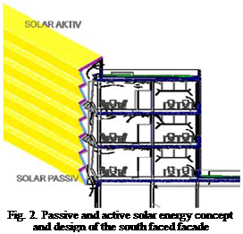 |
Figure 2 illustrates the solar energy concept and design of the south faced facade. Solar radiation is transformed into electricity by 400 m2 photovoltaics and as well as into useful heat by around 300 m2 flat-plate collectors. Due to the shape of the south faced facade the opaque elements follows two functions. Primary active solar energy systems are faqade integrated and generate power and heat and secondly overheating by solar radiation is prevented because of an optimal shading effect in summer of the opaque faqade elements. According to the passive house concept — which is already applied successfully in residential buildings — the passive use of solar energy in winter time is taken into account and this solar design of the south faced faqade reduces the heating demand of ENERGYbase office building and as well the daylight comfort is improved.
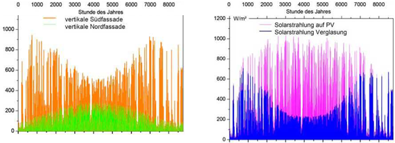
Figure 3 contains a comparison of solar radiation on a vertical south faqade and vertical north faqade. As well figure 3 shows the annual performance of solar radiation on two different surfaces with different declination, e. g. on one hand solar energy which is available on the transparent parts of the south faqade and on the other hand on the active solar components. Two important results are stated by analysing this annual performance of solar energy on different orientated surfaces:
• In summer the south faqade performs like a vertical north faqade
• The special design of the south faced faqade increases the amount of solar radiation in the range of 38% in comparision to vertical south faced faqade, e. g. active solar components generate much more energy.
1.2
 |
Solar-assisted air-conditioning system
The energy systems of ENERGbase office building are designed to use both a water based and an air based energy distribtion system. The basic temperature control of the office areas is realised by the water based heating and cooling system. The air treatment system is only designed in order to control indoor humidity and to supply fresh air to the offices. Consequently the air-conditioning unit is dedicated to treat only supply air, e. g. it controls and covers only latent loads. Herewith the comfort requirements of the air-conditioning unit are much more moderate in terms of energy use. arsenal research proposed to implement a solar-assisted air-conditioning system which is based on the standard configuration of the desiccant evaporative cooling technology and contributes strongly to achieve the energy targets of ENERGYbase (energy efficiency and use of renewables).
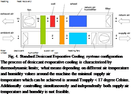 |
The energy efficient air-conditioning technology is using three thermodynamic processes in order to treat supply air: 1) dehumidification of ambient air by means of a rotating sorption wheel 2) precooling by means of adiabatic cooling in return air combined with an energy efficient rotating heat recovery wheel and 3) evaporative cooling of the supply air by means of a humidifier. Figure 4 shows a standard configuration of the desiccant evaporative air-handling unit.
Aiming an energy efficient air treatment by means of solar-assisted DEC technology the system requires high solar fractions for the regeneration of the sorption wheel and for supply air heating in
|
.S о ’-О ев w * 5P S /-Ч |
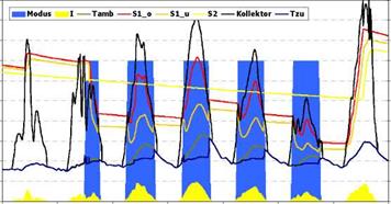
winter. arsenal research applied transient system simulation (TRNSYS 16.1) in order to estimate solar fractions and to assess the DEC system performance. Standard TRNSYS types were used and adapted, but the control of the interactive DEC performance is a complete new developement. Figure 5 shows all relevant air treatment components of a DEC system and the control sequence demonstrating when is which component is activ.
|
Operating mode
Fig. 5. Control strategy which was developed in order to simulate the annual performance of standard Desiccant Evporative Cooling systems configuration |
Transient system simulation were conducted by taking weather data from METEONORM Software (4) for Vienna. The solar system is modelled by flat-plate collectors of around 285 m2 gross area and coupled with two hot water storage each 7.400 l volume. The flat-plate collector type is a SONNENKRAFT SK500N-ECO and is oriented to the south/ 31,5°. Table 1 lists the relevant collector curve coefficients which have been put into the collector modell and used in the transient simulation. The solar system is operated in low flow and the specific mass flow of the flat-plate collector was set to 20 kg/hrs. m2. The TRNSYS simulation time step was defined as a 5 minute interval.
Figure 6 contains transient simulation results of the DEC system performance during one summer week. The ambient air temperature achieve values above Tamb > 30°C and the solar radiation varies day by day. Regarding the simulation results following statements can be stated:
• Considering the selected summer week the DEC system operates mainly in full desiccant evaporative cooling mode, e. g. dehumidification by means of sorption wheel, evaporative cooling by means of return and supply air humidifier and as well heat transfer by means of the heat recovery wheel;
• On sunny days the flat-plate collector system generates sufficient temperature Tcoll < 90°C in order to load the hot water storage;
• On sunny days the hot water storage system provides sufficient temperature around Tstorage < 70°C; an effective temperatures stratification is achieved; on dys without DEC operation hot water storage temperature exceeds Tstorage > 85°C;
• The DEC system is operated solar autonomously, 100% regeneration heat is supplied by the solar system, the DEC system provides supply air temperature in the range of Tsupply air < 23°C also when ambient temperature exceeds Tamb > 30°C;
• According to the cooling concept — where indoor temperature control is done by the water based thermal mass activation and not by air ventilation — it is possible to operate the ENERGYbase DEC system 100% by solar energy;
![]()

![]()
![]()
![]()

 100
100
90
80
70
£ 60 50
w
40
|2
30
20
10
4680.50
The solar DEC system operation will be monitored by arsenal research in 2009 and there will be an assessment and comparison study between transient system simulation results and measured performance data.
2. Conclusion
Passive house standard has long been successfully applied in residential buildings. However, there are comparatively few examples of the passive house standard being applied in larger building complexes across Europe. Three main principles serve as the basis for the passive house concept: insulation against the loss of heat, air-tightedness, and controlled ventilation with heat recovery.
In the design process of the ENERGYbase office building a three step approach was excecuted:
1) building form follows energy — e. g. reducing the energy demand for heating cooling and airconditioning as much as possible and using daylight as much as possible 2) implementation of energy efficient HVAC systems coupled with low temperature distrubtion systems 3) using renewable energy sources as much as it is possible on-site.
One of the innovative features of ENERGYbase is the exclusive use of renewable energy. The access to local wells water allows to use geothermal energy which completely covers all sensible heating and cooling requirements. Furthermore, 400 m2 photovoltaic panels located on the south facing facade of the building supply around 10% of the total electricity requirements. An innovative ventilation concept enables the integration of solar energy in summertime by means of solar-assisted desiccant evaporative cooling system, as well as the use of greens plants to ensure ecologically-friendly, controlled humidification in winter.
During the planning phase a significant scientific support was provided by using expert tools — like transient building and system simulation and computational fluid dynamics. Whether the energy and comfort targets will be achieved in real operation this is going to be assessed by arsenal research by using comprehensive monitoring equipment which is already implemented.
Taking the results from transient building system simulation and values from practise ENERGYbase is going to require around 57 kWh el/m2 which corresponds to a primary energy demand of 153 kWh/m2 (electricity to primary energy conversion factor of 2.7). This is a significant reduction of primary energy demand in comparision to a standard office building arcross Europe. ENERGYbase will yearly save around 180 tons of CO2 emissions.
ENERG ENERGYbase construction costs are around 14.5 Mio. € which corresponds to specific investment of 1.930 € per square metre useful area. The specific investment for standard Austrian office building is around 1.200 € per square metre useful area. Participants of the ENERGYbase planning team were Vienna Business Agency (developer); POS Architekten ZT KEG (architecture); KWI Engineers GMBH (HVAC planner); RWT plus (building statics); arsenal research (integration of renewables energy systems/ simulation / monitoring); OGUT (project coordination Interreg IIIA/ Know-how transfer); IBO — (building physics); Energy Center Bratislava; Institute of Thermal Engineering at the Graz University of Technology (simulation green buffer).
ENERGYbase — designed for a sunny office future — will serve as a reference project highlighting the compatibility of ecological and economic considerations in the construction of state-of-the-art office properties. Since August 2008 ENERGYbase construction phase is finished and the commissioning of each energy related system has been started.
Acknowledgment
ENERGYbase project is funded by European Commission — Programme INTERREG IIIA Austria — Slowakia, by Wiener Wirtschaftsforderungfonds (WWFF/ISTEG), by Programmlinie „Haus der Zukunft“ of the BMVIT, by the City of Vienna — Photovoltaik-Forderungsfonds.
References
[2] FLUENT, Fluent Deutschland GmbH, Darmstadt, Version 6.2, 2005
[3] TRNSYS, Transient System Simulation Program, Solar Energy Laboratory, University of Wisconsin Madison, Version 15.09, 2001
[4] METEONORM Version 5.1 Copyright METEOTEST Fabrikstrasse 14, CH-3012 Bern, Switzerland, Swiss Federal Office of Energy, CH-3003 Bern, November 2004
Thin films of Tin Iodide (Snl2), Manganese Bromide (MnBr2), Lead bromide (PbBr2), Lead Iodide (Pbl2) Lead Sulphide (PbS) and Silver Sulphide (Ag2S) were grown on glass slides using the Chemical Bath Deposition (CBD) method also called the Solution Growth Technique (SGT) [2, 9, 10]. The surface structures of the films were obtained by taking photomicrographs of the films with a Leitz Labourlux Photomicroscope. The photomicrographs were then used to study the surface microstructure of the films by applying the Jeffries (Planetric) measurements with a circle 79.8mm in diameter drawn on a transparency. This drawn circle was placed on each photomicrograph one after the other to count the number of grains falling within the circle N1 and those intersecting the circle N2. The values of N1 and N2 were then used to compute the grain size parameters by applying equations 6 to 15, while the porosity factors were obtained with equations 16 and 17. Only films whose thickness is such that the individual grains are visible and identifiable on the photomicrographs were used for this study [2, 4].
After taking the photomicrographs of the films the coated slides were then put in the transmission beam path of a Pye-Unicam (Sp 1000) spectrophotometer to obtain the spectral transmittance curves of the films, with a similar but blank glass slide in the reference beam path of the spectrophotometer.

Plates 1 = 6 show the photomicrographs of the films mentioned above respectively, while table 1 shows the computed grain size parameters and porosity factors for the films. Figs 1 — 3 shows the spectral transmittance curves of the films.