Как выбрать гостиницу для кошек
14 декабря, 2021
1.1. The ejector characteristic curve
The ejector works according to a characteristic curve. For given Pe and Pg, the ejector works at on — design conditions as long as the condenser pressure Pc is lower than a critical backpressure Pc*, such as the chocking in a simple nozzle. This on-design working is characterised by a constant and
maximal entrainment ratio U = m tm and coefficient of performance COP =—————- Q——— .
gr v Q + Q + Q
g sup pump
Pc obviously increases with the external temperature. When Pc>Pc*, the ejector performances drop noticeably and the ejector works at off-design conditions. It is worth noting that U and Pc* are strongly dependent on Pe and Pg. Pc* is higher for high Pe and Pg. U is higher for high Pe and low Pg. It is important to highlight that the pseudo-1D model used for the ejector in the rating model cannot predict the off-design conditions, that is when Pc>Pc*. Only the optimal working point (maximal U, Pc*) obtained for given pressures and temperatures conditions at the ejector inlets is computed.
The aim of the rating model is to evaluate and predict the variations of performances for a given EACS installation, when this system is submitted to different external thermal and/or operating conditions. In the proposed experimental stand, the water will be used as coolant for the condenser, generator and evaporator. Each inlet water temperature and mass flow rate is hence given. All plate heat exchangers and ejector dimensions are given as well. The design was previously computed with the sizing module which gives the best design for the desired operating condition: in the design process, the cooling capacity Qe and a heat capacity Qg were of 5 and 12 kW respectively. The saturated temperatures Tgsat, Tesat and Tcsat were 90°C, 10°C and 40°C respectively. All the inputs of the rating model are reported in the table 1.
|
Ejector dimension [mm] |
Exchange surface A [m2]/plates number N |
|
Dt D1′ D2′ Dd Ddif 2.2 3.2 6.9 4.5 6.3 |
Ag Ac Ae Asup Ng Nc Ne Nsup 1.26 2.48 2.59 1.14 21 42 29 19 |
|
Table 1. Inputs of the rating model. See figures 1 and 2 for nomenclature. |
|
Mass flow rate [kg/s] |
Temperature [°C] |
|
mgw mcw rhew a(%) 0.233 0.792 0.199 0.130 |
T T T eiw ciw supiw 18 32 100 |
Two additional heat exchangers, depicted in fig. 1, were envisaged to improve the whole EACS performances:
— A subcooler, to cool mer before its expansion in the throttling valve, with the refrigerant leaving
the low pressure separator (after evaporator). A previous study permitted to deduce the most judicious exchange surface of the subcooler, namely 2m2 [5].
— A regulator: A part в ofmew, initially devoted to create the cooling effect is extracted from the
evaporator to cool rhcw in the condenser. The use of such a heat exchanger aims at reducing Pc
until it reaches Pc*, allowing the ejector to work-back at on-design conditions. It is worth noting that even if a lower cooling power is available, this loss of cooling is obviously smaller than the loss that would occur with the steep drop of U beyond Pc* (cf. fig. 3a, off design prediction). A succession of on/off states is moreover avoided with the regulator.
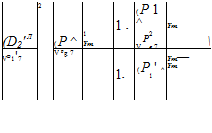
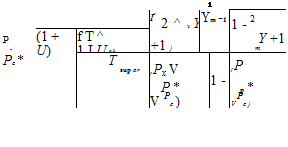
A pseudo-ID model is used to compute the thermodynamic properties within the ejector. The energy and momentum equations of conservation are applied to large control volumes in the ejector. The calculation procedure was described for the sizing module (Hemidi et al. [5]). From the geometry and thermodynamic conditions at the ejector inlets, U, Pc*, are computed. mgr is
determined by the well known isentropic relations. mer is hence deduced.

![]()
![]()
![]() (1)
(1)
*
Pc* is computed iteratively:
 |
At each main heat exchanger, the pressure depends on the geometrical configuration, the temperatures, the mass flow rates and the equilibrium between the heat exchanger and the separator. At the separators, the refrigerant is at saturated state. If the heat exchanger is undersized, the refrigerant is at two phase state. To compute the saturated pressure for each heat exchanger, the following methodology is used:
— Two pressure thresholds are determined:
• For a given surface of a heat exchanger, only one pressure corresponds to the case of a total evaporation/condensation. The refrigerant is on the saturated curve at the exit of the heat exchanger, any recirculation occurs. This pressure is determined by iteration until the computed surface corresponds to the actually available surface;
• The second threshold is the pressure for which the heat exchanger efficiency is 1. This matches to a zero pinch and it is obviously never the case.
The real pressure is estimated between both of these thresholds:
|
|||
|
|
||

The parameter Ф is computed iteratively until reaching a pressure for which the surface required to do a total phase change is slightly higher than the actual surface. However, the thresholds difference remains small.
— Once the real pressure is known, iterations on the vapor quality xv at the heat exchanger exit are made until the computed and actual surfaces are equal. The refrigerant state at the exit of the heat exchanger is deduced, as well as the transferred power Q.
To compute the surface required for the heat transfer, the s-NTU method is applied. The following procedure is used:
— Calculation of the global heat transfer coefficient Hoverall:
|
|
|
|
|
|
|
|
|
|

The heat transfer coefficients Hr and Hw are predicted with different correlations: Dittus and Boelter, Nu = 4.36 or interpolation according to Reynolds number for the single-phase flows, Chen correlation for ebullition in the generator and the evaporator, Shah correlation for condensation. Note that single-phase (superheat, subcooling) and two-phase flows can coexist. This methodology is hence applied separately for the single and two-phase part.
— Calculation of the efficiency s:
![]()
![]() _____________ Qactual__________
_____________ Qactual__________
(m ■ Cp) . x T — T
mm гг iw
where (m ■ Cp)min = min(m wCpw, mrCpr)
— Calculation of the Number of Transfer Unit NTU: ( m ■ Cp)
r _____ _V____ 1 /min
(гіг ■ Cp)
max
*
![]() NTU = 1 ln 1 — R
NTU = 1 ln 1 — R
The exchange surface A is deduced by:
![]() NTU •(m • Cp) .
NTU •(m • Cp) .
A =______ 1___ _^mm
H
overall
2.1. Influence study of the external temperature Tciw
As seen before, the climatic conditions have a noticeable effect on the ejector systems. Hence, this investigation presents the performances variations of the EACS with Tciw (which reflects the external temperature variation), with or without the subcooler and for two values of a.
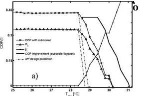
The figure 3a and 3b allow comparing the COP when the subcooler is used or not. A first remark is that the optimal working zone, characterized by P = 0, is reduced of about 1°C when the subcooler is used (critical point at Tciw = 28.4°C against 29.5°C without subcooler). In fact, the rise of Tej2 leads to a decrease of Pc*. In this zone of optimal working, the COP and Qe are better with 6.7% and 6.6% of increase respectively for Tciw=28.4°C. But the figure 3b shows that U is lower when the subcooler is used. The thermodynamic conditions remaining constant for the high pressure side, mgr is constant. But the rise of Tej2 involves the drop of U and thus of mer. In spite of that, the
increase of enthalpy difference Ahe is more noticeable, so performances are improved when the subcooler is used. This proves that seeking a best ejector entrainment ratio does not guarantee the best cycle operation, and that the overall cycle has to be taken into consideration for a performance study of an EACS. When Pc is greater than Pc*, the EACS is at off-design. The regulator is hence requested, and a part P of mew is used to reduce Pc under Pc*. p is all the higher as Pc increases and the lower are Qe and COP. Moreover, by comparing the COP obtained with and without the use of the subcooler when Pc is beyond Pc*, an important observation is that the subcooler has a harmful effect on performances. For instance, for Tciw = 29.4°C, COP = 0.41 without subcooler, and COP = 0.21 when the subcooler is used. It is concluded that as long as P = 0, the subcooler have to be used to improve the EACS performances. But when p > 0, the subcooler becomes unfavorable. A bypass of this heat exchanger is required from this moment to optimize the EACS working.
|
■ ■ ■ … |
Q, without subcooler e Q, with subcooler e |
|
■+++++~v ‘……………………………………………………………. : ++*++ ‘ ■ ++ 1 і ++ і і і |
U, without subcooler U, with subcooler |
|
***x 1 |
|
|
x ‘ 1 |
■ |
|
b) x |
|
0.56 0.55 0.54 0.53 0.52 0.51 0.5 0.49 0.48 0.47 |
|
4 |
|
22 |
|
24 |
|
26 |
|
28 |
|
30 |
|
32 |
|
34 |
|
T. [°C] ciw |
 |
Figure 3: a) COP, p and Qe vs. Tciw, with and without the subcooler, for a = 0.13.
b) Qe and U vs Tciw with and without the subcooler, for a = 0.13.
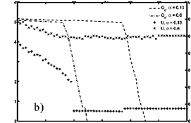
For a given a, the figures 4a and 4b show that the COP and Qe are relatively constant until a certain value of Tciw, and then drop. In fact, Pc increases with Tciw. It is seen that Pg rises with Tciw in a first time and becomes constant after. Thus U decreases, Pc* increases because of Pg, but less noticeably than Pc, such that Pc becomes higher than Pc*. The regulator starts working, and Qe and COP drop.
When a decreases, it is obvious that a lower superheat is performed but Pg is higher. Hence Pc* is higher (Pe remains constant) and the optimal working zone is higher. It is observed as well that COP is slightly higher as long as Pc remains lower than Pc* (fig.4a), despite the fact that Pg is higher for low a. Actually, the rise of mgr resulting from Pg increase is balanced with the decrease of Ahg that occurs near the critical point of propane. For low a , Qg is only slightly higher.
 |
 |
Furthermore, although U is lower (higher Pg, Pe constant), a better Qe is obtained, and gets the better of Qg (fig.4b). When p > 0, a low a is judicious too (fig. 4a): for instance, for Tciw = 26.8°C, the EACS works at optimal conditions for a = 0.13 (COP = 0.41), but the COP drops when a rises (COP = 0.05 for a = 0.6).
Figure 4: a) COP vs. Tciw for different a, without the subcooler.
b) Qe and U vs Tciw for different a, without the subcooler.