Как выбрать гостиницу для кошек
14 декабря, 2021
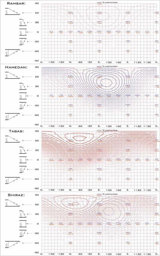
Previous diagrams show the intensity of desirable/undesirable direct radiation in each moment on a surface perpendicular to the rays of the sun so they are not usable for different side of buildings.

To achieve the kind and unkind faces of the sun for each direction, applying the effect of incidence angle in each moment is needed.
As the second row of above diagrams shows, the south direction of building has two advantages: it reduces the unkind face of the sun in summer and it receives more from its kind face in winter.
|
|
1st International Congress on Heating, Cooling, and Buildings " ‘ 7th to 10th October, Lisbon — Portugal *
Fig. 6. Generating the scores for each direction and slope from average and percentage of +/- values |
F. Giovannetti1* and K. H.C. Fischer2
1 Institut fur Solarenergieforschung Hameln (ISFH), Am Ohrberg 1, 31860 Emmerthal, Germany
2 Karl Fischer Glasgrobhandlung, Gottlieb Daimler-Str. 46-48, 71711 Murr, Germany
* Corresponding Author, giovannetti@isfh. de
The paper presents experimental results of suitability tests for the use of microstructured films as suspended layers with light-redirecting properties in multiple glazing systems. Our investigations focus on the optical and the mechanical properties of the films as well as on the durability of the insulating glass units. UV-stabilized composite films are identified as best performing product and are thus chosen for prototyping a prismatic film designed for seasonal shading. Simulations based on measured material data confirm the potential of the system under development, which combines improved insulation, passive use of solar energy and overheating protection. For a triple glazing with 2 low-e coatings we calculate a thermal transmittance (U-value) between 0.6 and 0.8 W/m2K, depending on the gas-fill and the gap width, and an incident angle dependent solar heat gain coefficient (SHGC) variable from 0.58 to less then 0.10.
Keywords: glazing, solar energy gain, overheating control, microstructures
1. Introduction
Static or movable prismatic systems have been in use for a long time in architecture as sun-shading or daylight redirecting devices [1, 2]. Due to the high costs related to the elaborate manufacturing and integration, their use is limited to demonstration or prestigious buildings so far.
As their optical functionality is independent of the prism dimension, the replacement of expensive panes by microstructured films is a promising approach to reduce the overall cost of this type of products, which could help to develop a larger market. Appropriate technologies and materials to manufacture large area microstructured films for architectural applications have been intensively investigated in the last years [3, 4]. Further work is now required with regards to assembly, characterization and long term monitoring of the whole glazing system.
The purpose of the project presented in this paper is the development of a cost efficient and energy saving multiple glazing for the use in glass facades or transparently insulated walls, which integrates a prismatic film as seasonal shading device [5].
The insertion and suspension of a film, which has already successfully been implemented with low-emissivity coated films, is here investigated with structured film as an alternative solution to lamination. This results in a triple unit with two air or gas gaps without having the weight and the thickness of a triple insulating glass (Fig.1).
T. Selke1*, A. Preisler1 and U. Schneider2
1 arsenal research, Austrian Research Centre, 1210 Vienna, Austria 2
pos-architekten, 1080 Vienna, Austria
* Corresponding Author, tim. selke@arsenal. ac. at
The usage of renewable energy booms not only in residential buildings, but also achieves more and more acceptance in commercial buildings. The building „ENERGYbase“(1) in the 21st district of Vienna, with 7.500 m2 useful area shows, how office buildings in the future may look like. The architectual and energy concept of the office building focuses on sustainable, innovative technologies as passive house standard for the building envelope, ground coupled heat pumps, free cooling, solar air-conditioning, building integrated photovoltaics and ecological air humidification by using plants in the ventilation system. The occupants of ENERGYbase building will be mainly business companies and institutions for research and education in the field of renewable energy.
To keep the primary energy demand as low as possible the energy performance of ENERGYbase concentrates on the use of locally available renewable energy sources. First geothermal heat is used by wells water for heating with heat pump and for cooling by free — cooling. The energy distribution system of the office building mainly operates by using thermal mass activation, therefore high efficiency can be achieved with the heat pump system, direct free-cooling is possible and also high indoor comfort by radiant heating and cooling can be provided. Solar energy is actively used three times in the south faced facade: solar-assisted air-conditioning in summer, heating support in winter and production of electricity all season long by photovoltaics. Therefore, the south facade is equipped with 300 m2 solar thermal collectors and 400 m2 photovoltaic panels. The special convolution of the south faqade allows on the one hand high solar gains in the solar active components and on the other hand the components performs as sun protection elements for the office areas behind.
Basic requirements for such an energy performance concept, is a solar and energy efficient architectural concept. The sum of actions begins with the big compact volume of 30.000 m3 and the solar orientation of the building shape. Several other parameters, which reduce the heating and cooling demand, have been taken into account from the very beginning as the thermal quality of the building envelope, low infiltration rate, quality of glazing and sun protection, sufficient storage mass, etc.
Nevertheless, the ENERGYbase building has a high ratio of glazing; the entitlement on architecture was to provide high daylight quality, to illustrate an intelligent and energy efficient design of direct sun light use in an office building.
As a consequence the heating and cooling demand of the whole building can be covered by the use of ground wells water and solar energy, only for the energy distribution additional electricity is needed. The building and its heating, cooling and air-conditioning system is equipped with a comprehensive monitoring system in order to evaluate the applied innovative technologies in operation and to identify further development demands.
Keywords: Sustainable, innovative technologies in office building, passive house concepts, ground coupled heat pumps, free cooling, solar air-conditioning, building integrated photovoltaic and ecological air humidification.
1. Introduction
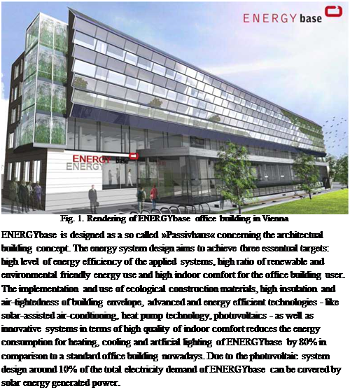 |
The office building project ENERGYbase in Vienna is based on results of an Austrian research project »Sunny research« which was prelimary performed, funded by the Austrian research programme »Haus der Zukunft« and directed by arsenal research.
H. Gonfalves, A. Silva, A. Ramalho, C. Rodrigues
INETI, Department of Renewable Energies, Campus do Lumiar do INETI, 1649-038 Lisbon, Portugal
Corresponding Author, helder. goncalves@,ineti. pt
This paper presents the thermal performance of a Passive Solar Office Building in Portugal in winter and summer 2006 and 2007. This Building, called Solar XXI, pretends to be an example of passive design both for heating and cooling. It contains a direct gain system assisted by a solar thermal system for winter conditions. In summer a ground cooling system (buried pipes) is used to cool the building, together with night cooling strategies. It also integrate in the vertical south envelope a Photovoltaic System (12 kWp) which provide around 12 MWh per year plus a 6kWp in the car parking, which correspond to around 76% of the electric energy consumption of the building. The integration of the PV system, in the building was done in such a way, that it is possible to recovery the heat production from the PV in order to be used for heating purposes Keywords: Passive heating and cooling (ground, night ventilation), PV heat recovery
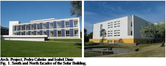 |
The main goal of this project was the design of an office building, with low energy consumption, integrating renewable technologies (Solar thermal and Photovoltaic System) and passive systems for heating and cooling purposes, full integrated in the architecture design. The building pretend to be an example for new projects and it is an experimental facility of INETIs Renewable Energy Department. The building has 1500m2 in three floors, with the main occupied spaces in the south of the building and the less occupied rooms in the north part of the building.
a. The ASTM defines grain size as the number of grains per square inch at (x 100), and this is given as:
n = 2Gn -1……………………………………………………. 1
 |
Where n = number of grain per square inch at (x 100), and Gn = grain size number given as:
The International Organization of Standards (IOS) defines grain size as the number of grains per square millimeter at (x 1), and is given as
m = 8(2Gm )……………………………………………………………………………. 3
Where m = number of grains per square millimeter at (x 1) and
 |
Gm = grain size number, given as:
But Gn and Gm are related by the equation [2, 4]
Gn = Gm — 0.045 ……………………………………………………………………………….. 5
The Jeffries method provides the value of N_ =number of grains per unit area which is an
A
equivalent of n or m. From this, the grain area, A and grain diameter, d can be obtained.
The Jeffries planetric method is generally employed by drawing a circle 79.8mm in diameter (i. e 5000mm2) on a photomicrograph or on a transparency placed on it. The magnification is adjusted to provide at least 50 grains within the test area. The number of grains falling within this area is counted and designated n, the number of grain intersecting the test circle is also counted and designated n2. The total of (n + n2)/2 is multiplied by the Jeffries factor f for the magnification with 79.8mm diameter circle to obtain an estimate of the number of grains per square millimeter.
This is given [4, 6] as:
N_ = f (П1 + П2 )/2………………………………………………………… 6
This is the value of N_ for each equiaxed grain. For non-equiaxed grains, grain count is done in
A
three mutually perpendicular planes (longitudinal N_ , transverse N_ and normal
A1 At
N_ directions). Then the number of grains mm3 is given as
A n
N_ =[ N_ + N_ + N_ ]/3…………………………………………………………. 7
A V A1 At An J
Therefore the value of f for any magnification is found using the equation
M2
5000………………………………………………..
The average grain area A is obtained from
|
|
|
|
|
|
|
|
|
|

While the mean grain diameter d is obtained from
|
|
|
|

The ASTM grain size number is obtained from the formula [2]:
Gn = (3.322 log Na) — 2.95 …………………………………………………………….. 12
While the IOS grain size number can be obtained from Gm = Gn + 0.045 = (3.322log Na) — 2.95 + 0.045
= (3.322log Na) — 2.905 ……………………………………………………………….. 13
To obtain good results, the grain must be marked off, as they are counted to prevent miscounts. G is also usually rounded off to the nearest one-half unit. Also, the number of grains per unit area Na has been shown to be directly related to Lv the total length of grain edges per unit volume by [2, 4]
Lv = 4Na…………………………………………………………………………………………………. 14
1.1. Model house
As shown in Fig. 1, the standard model house of the Architectural Institute of Japan was used for the simulation. This model house is facing south and a wooden two-story single house. And a total floor is 125m2. The house is supposed to be occupied by a family of husband and wife and two children. The solar space and hot water heating system is modeled, as shown in Fig. 2. Solar collector 12m2 is mounted on a roof. A heat storage tank is only for domestic hot water (DHW) supply. The solar heating is used also for the floor heating. The room air conditioner is used as an auxiliary heat source in winter and cooling in summer. Expect in winter, a solar heating is used only for DHW heating.
|
3185 910 1820 2730
Fig. 1. Floor plan of the south Fig.2. Simulation model for a single-family house with facing house. floor and hot water heating system |
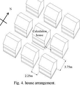
The calculation cases were three cases as shown in Fig. 3. Case A is no adjacent houses and no active solar heating system, case B is adjacent houses and no active solar heating system and case C is adjacent houses and active solar heating system. The location was Tokyo (35degrees, North), Japan. The meteorological data used is the standard year weather data set of Tokyo prepared using AMeDAS data[5].
As shown in Fig. 4, the north and south distance is 3.75m and the east and west distance is 2.25m in the house arrangement in the Cases B and C. This assumes the typical residential area in the suburbs of Tokyo in which building ground area for a site area is about 50%. As shown in Table 1, building thermal insulation of the walls, ceilings and dirt floors are 135mm, 265mm and 100mm of a glass fiver, respectively, and the windows are transparent double glazed glass (3+A6+3) . The heating and cooling seasons are supposed as shown in Table 2. The space heating and cooling schedule and the set point temperature using the operative temperature are shown in Table 3. The domestic hot water (DHW) is supplied from the solar storage tank and the auxiliary boiler. Although DHW flow rates is changed according to a season and holiday or weekday etc, daily DHW flow rates are average 370 liter/day. The hot water set point temperature of DHW supply is 35oC from 0:00 to 20:00 and 42oC from 20:00 to 24:00. It is assumed that the outlet hot water temperature of the boiler is 52oC. As the data for the internal heat generation caused by lighting and household equipment, the dairy value summarized from hourly schedule of household
 |
appliance is 40MJ/day. The infiltration rate is assumed to be of 0.5 air change/hour throughout a day. In addition, the additional ventilation rate from the kitchen is assumed in the cooking time. For shading and insulation of the windows, light drapes and heavy drapes are used in the daytime and the night, respectively.
2.
![image066 Подпись: Ceiling [mm] Wall [mm] Floor [mm] Windows 265 135 100 Transparent double-glazed glass (3+A6+3) Table 2. Heating and cooling season](/img/1153/image066.png) |
 |
 |
 |
Simulation result
The concerned problem mainly stems from lack of renewable energy policies, city-planning strategies without solar, systems regulations of municipalities and the insensitive approaches of the users. In a general way of looking the practical reasons of the problem can be summarized as; [3]
• Minority of central system applications, difficulties in multiple usage, common usage of
individual applications and natural convection systems,
• Variety and irregularities of the color, form of the storages, the collectors and the way of
applications,
• Undistinguished system components, and absence of completeness and integrity,
• widespread garage manufacturing, usage of bad quality components and poor applications
• Lack of maintenance, repair and recycle of descript systems,
• Lack of product developments that would provide opportunities for innovative application in the
consideration of climate.
• Non-consideration of solar energy as a design criteria in the building design process,
• Due to not being considered solar hot water systems as a design criteria, — despite their common
usage — absence of appropriate surfaces in suitable direction, inclination and dimension for collector areas,
• Not considering solar hot water systems as an architectural component,
• Non-integrated and enharmonic collector areas with architecture
When we approach to the problems that systems bring to the architecture and city from different point of views it appears that, separate approaches has to be taken together which are bound, accomplish and trace each other in order to achieve the desired results. In order to prevent the inconveniencies; primarily political and administrative regulations has to be constituted, the consciousness of consumers and producers has to be improved and buildings have to be designed with respect to sustainability principles.[4] It is clear that to provide a permanent solution to the problem, parallel studies has to be executed in the mentioned areas. Beside this, it is important to make the renovation of existing systems with “good quality” applications which provide the efficiency — economy — aesthetical optimization and development of innovative approaches with architectural view for system integration to the buildings.
Physics Department, University of Patras, Patra 26500, Greece
Corresponding Author, yiantrip@physics. upatras. gr
New designs of building integrated concentrating photovoltaics (CPVs) and hybrid concentrating photovoltaic/thermal (CPVTs) systems are briefly described and aspects for their application are presented. Low cost concentration of solar radiation on PV or PV/T absorbers can be effectively achieved by using booster diffuse reflectors, linear Fresnel lenses or Compound Parabolic Concentrators (CPCs). The booster diffuse reflectors can be considered an effective solution for building roof PV or PV/T system installations. In the combined Fresnel lenses with PV/T absorbers, apart of electricity and heat production the system can operate as transparent material that controls the temperature of building interior spaces. The collection of a great part of the transmitted solar radiation is achieved, while the rest radiation is distributed in building interior space for the illumination of it. Laboratory tests showed that a considerable lighting and temperature reduction is achieved, adapting building cooling needs. In addition, stationary symmetric or asymmetric CPC reflectors can be effectively combined with linear strip type PV modules and flat thermal absorbers, resulting to novel PV/T systems. Some architectural designs give an idea about the effective integration of the suggested solar energy systems on building structure.
Keywords: Concentrating Photovoltaics, PV/T systems, Fresnel lenses, CPC reflectors
Aiming to cover the energy demand of buildings the solar energy systems are suitable and environmentally friendly devices. In new buildings or retrofitting the emphasis is addressed to the effective use of passive and active solar energy systems to partial or entire adapt of demand in natural lighting, space heating and cooling, air ventilating, domestic hot water and electricity. The emerging concerns for environmental protection and global energy saving have introduced new architectural design rules for buildings, aiming at buildings of reduced energy consumption with effective integration of solar energy systems in combination with satisfactory aesthetics as well. Solar energy systems as thermal collectors and photovoltaics are installed on the roof or the facade of buildings to cover hot water and space heating/cooling needs and provide electricity for lighting, operation of electric devices, etc. The application of photovoltaics (PVs) and solar thermal (STs) collectors is actually useful and efficient, considering the total energy consumption of buildings. Apart of the typical form of solar energy conversion systems (PVs and STs), new devices with innovative design have been developed and prototypes have been studied. The Physics Department of Patras University has long time research activities on solar energy systems, mainly for building integration, with low concentration systems being a significant direction of these works. In this paper a review of the most important designs for the investigated concentrating photovoltaic (CPV) and photovoltaic/thermal (PV/T) systems (CPVT) is presented, including some architectural designs to get a better idea about the possibilities for an aesthetic building integration of them.
Fig. 5 and Fig. 6 show the BIPV/T energy output in a commissioning test on Feb. 24th and March 17th, 2008. On Feb. 24th, the temperature of the air reached 30 °C under cold clear sunny conditions with outdoor temperature equal to 0°C. The average wind speed at roof height was about 3 m/s. On March 17th, the weather was almost the same as that of Feb. 24th except that the average wind speed was about 1 m/s. The BIPV/T outlet air temperature reached almost 40 °C. It can be observed that for every 1 m/s increase of wind speed, the outlet air temperature drops almost 5 °C, and secondly the outlet air temperature was not affected significantly by low cavity
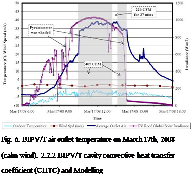
air velocity (e. g. 405 CFM flow rate results in 0.6 m/s air velocity). It can be concluded that under this condition it is beneficial to use the maximum flow rate so as to improve thermal efficiency.
 |
|
 |
|
![]()

![]() —- hc Section 2_3
—- hc Section 2_3
— hc Section 3_4 hc Section 4_5 Air Velocity
Fig. 8. CHTC vs. air velocity (April 24th, 2008).
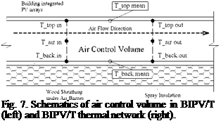
Fig. 7 shows the air control volume used to calculate the CHTC for a section of the roof. Fig. 8 shows the calculated CHTC for different sections. It is seen that CHTC keeps increasing over time under constant air velocity. The average CHTC value is about 15 W/m2K with an error of ±40 %.
Further work and CFD simulations are being performed by the Concordia Solar Lab to determine accurate correlations for CHTC.
 |
One dimensional explicit finite difference technique and upwind scheme [11] are adopted in modelling the BIPV/T system. A constant CHTC of 15 W/m2K is used for both the top and back surfaces. A grid cell size of 0.15 meters (36 sections for an 18 ft long path in this case) is used to predict the out air temperature to a very satisfactory degree (with an error of ±5 %.). The simulated temperature profiles are very similar to the measurement. Fig. 9 shows the comparison for one specified time.
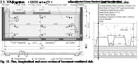
The VCS considered in this paper (Fig. 10) is located in the basement. It is coupled with the BIPV/T system for storage of the heat recovered from the roof. The air extracts the heat from the PV panels and then passes through the VCS. The VCS stores the heat and releases it passively into the living space. The desirable air temperature for heating the VCS could be just 3 to 10 °C higher than room temperature. That means that high PV temperature is not required for heating air; large amount of air at relatively low but useful temperature can be utilized. The overheating of the BIPV system is reduced and its efficiency and durability are enhanced. Meanwhile, much useful thermal
energy is produced. Note that the air entering the soffits is also heated significantly by the south facade of the house.
G. Carrilho da Graca1,2*, A. Augusto1, M. Lerer2
University of Lisbon, DEGGE. 2NaturalWorks, Lisbon.
Corresponding Author: gcg@natural-works. com
The Portuguese education ministry is in the process of modernizing the country’s high schools. The first phase of this operation comprises 172 buildings that will be rehabilitated and expanded. This initiative aims to improve indoor comfort in the schools (lighting, acoustics, ventilation and thermal comfort) as well as the environmental/energetic performance of the buildings [1]. This large rehabilitation effort coincides with the recent transposition (04/2006) of the 2002/91/CE directive on the energy performance of buildings. This study evaluates the possibility of integrating photovoltaic solar panels (PV) on the school roofs, creating a distributed renewable electrical energy production system. The expected PV generated electricity and the resultant reduction in CO2 equivalent emissions are estimated. Electrical production and avoided emissions will range between 20 and 31GWh/year, and 7 to 11 MtonCO2 /year, depending on the area of the system. The reduction in the net electrical energy consumption of the schools can exceed 60%.
Keywords: photovoltaic, integration, emissions
Most of the electricity consumed in Portugal is produced in large power stations (thermal, hydro) usually located far from the demand, resulting in relevant power losses in the grid (around 10%). The existing energy infrastructure must be improved to meet increased demand with reduced emissions. In this scenario distributed renewable electrical energy production systems are attractive, reducing power losses in the grid and decreasing dependance on fossil fuel. As expected, most of the portuguese high schools are integrated in populated areas and have large roof to floor area ratios (0.2-0.3), making them suitable to PV integration in the roofs. Integration of renewable energy systems in schools is also important from an educational perspective as the systems become part of the daily life of the students.
This large school rehabilitation effort coincides with the recent transposition (04/2006) [2][3][4] of the 2002/91/CE [5] directive on the energy performance of buildings. This new legislation imposes limits on primary energy consumption as well as thermal comfort standards. As in most working environments, improved thermal conditions should also improve the performance of students and teachers. Still, as most schools currently have limited or no climate control systems and poor ventilation, the introduction of ventilation and air conditioning systems will result in increased energy costs. In this context the PV system may have the additional advantage of reducing the energy bills that schools will be faced with after the renewal process.
In order to evaluate the feasibility of this system we will answer the following questions:
• What is the area available for solar energy collection (roof area)
• What is the cost and payback of the PV systems
• What is the the impact in the electrical energy demand of the schools
• What is the reduction in overall Portuguese CO2 emissions.