Как выбрать гостиницу для кошек
14 декабря, 2021
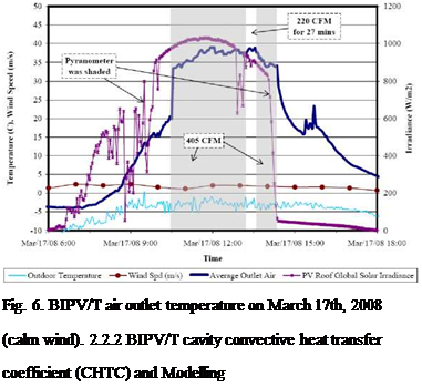
Fig. 5 and Fig. 6 show the BIPV/T energy output in a commissioning test on Feb. 24th and March 17th, 2008. On Feb. 24th, the temperature of the air reached 30 °C under cold clear sunny conditions with outdoor temperature equal to 0°C. The average wind speed at roof height was about 3 m/s. On March 17th, the weather was almost the same as that of Feb. 24th except that the average wind speed was about 1 m/s. The BIPV/T outlet air temperature reached almost 40 °C. It can be observed that for every 1 m/s increase of wind speed, the outlet air temperature drops almost 5 °C, and secondly the outlet air temperature was not affected significantly by low cavity

air velocity (e. g. 405 CFM flow rate results in 0.6 m/s air velocity). It can be concluded that under this condition it is beneficial to use the maximum flow rate so as to improve thermal efficiency.
 |
|
 |
|
![]()

![]() —- hc Section 2_3
—- hc Section 2_3
— hc Section 3_4 hc Section 4_5 Air Velocity
Fig. 8. CHTC vs. air velocity (April 24th, 2008).
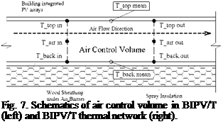
Fig. 7 shows the air control volume used to calculate the CHTC for a section of the roof. Fig. 8 shows the calculated CHTC for different sections. It is seen that CHTC keeps increasing over time under constant air velocity. The average CHTC value is about 15 W/m2K with an error of ±40 %.
Further work and CFD simulations are being performed by the Concordia Solar Lab to determine accurate correlations for CHTC.
 |
One dimensional explicit finite difference technique and upwind scheme [11] are adopted in modelling the BIPV/T system. A constant CHTC of 15 W/m2K is used for both the top and back surfaces. A grid cell size of 0.15 meters (36 sections for an 18 ft long path in this case) is used to predict the out air temperature to a very satisfactory degree (with an error of ±5 %.). The simulated temperature profiles are very similar to the measurement. Fig. 9 shows the comparison for one specified time.
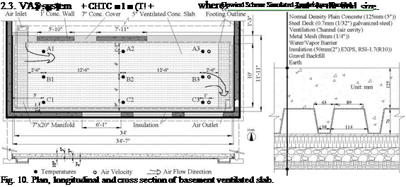
The VCS considered in this paper (Fig. 10) is located in the basement. It is coupled with the BIPV/T system for storage of the heat recovered from the roof. The air extracts the heat from the PV panels and then passes through the VCS. The VCS stores the heat and releases it passively into the living space. The desirable air temperature for heating the VCS could be just 3 to 10 °C higher than room temperature. That means that high PV temperature is not required for heating air; large amount of air at relatively low but useful temperature can be utilized. The overheating of the BIPV system is reduced and its efficiency and durability are enhanced. Meanwhile, much useful thermal
energy is produced. Note that the air entering the soffits is also heated significantly by the south facade of the house.