Как выбрать гостиницу для кошек
14 декабря, 2021
Most feed-in laws for decentralised and fluctuating generation guaranty a fixed payment for each kWh fed in. Typically an operator will try to maximise the operation hours of his plant to increase produced electricity and with it his return. This thermally driven operation does not regard any restrictions of the electricity grid. To motivate the local operator for an electrical and thermal coordinated operation of the CHP we suggest a variable and local component to the price curve for the produced electricity, which represents the transport capacity of the distribution grid.

3.1. Contact area and scanning equipment
Contact area between two adjacent p-n-n+ junctions is most important for investigation in order to achieve better characteristics and parameters of solar cells with vertical p-n — junctions such as high efficiency and fill factor, low series resistance, high mechanical and thermal tolerance. Cross-section of the contact area is shown at Fig.7.
Nanocenter of the MPEI (TU) is participating in our research activity. Using INTEGRA Prima scanning probe microscope (SPM) we are analyzing quality of soldering processes, relief and physical properties of boundaries of vertical semiconductor structures. SPM gives an opportunity to carry out studies of spatial, physical and chemical properties of objects with the typical dimensions of less than a few nanometers (Fig.8). Owing to its multifunctionality, availability and simplicity, atomic-force microscope has become useful tool.
Below the several examples of taken images are shown. With help of video-microscope it is very convenient to observe quality of soldering structures at the different magnifications (Fig.9).
|
Fig.9. Images of SCs with vertical p-n-junctions at the consecutive magnifications (from left to right) |
Three-dimensional image taken with help of atomic force microscope is depicted at Fig. 10.
|
Fig. 10. Three-dimensional image of contact area (10 p scale divisions are shown) |
Topology of Al layer and adjacent area is shown at the Fig.11. At the next stage of research we are planning to use scanning capacitance microscopy, which allows mapping variations in electron carrier concentration across the sample surface with the unprecedented sensitivity, but we need to solve potential problems with samples that are too rough.
|
Fig. 11. Topology of Al layer and adjacent area (scan field 170 p, resolution 670 nm); topology of the surface, marked out by green square at first scan (scan field 70 p, resolution 270 nm); topology of the surface, marked out second (scan field 11p, resolution 40 nm). |
Author thanks Federal Agency on Science and Innovations of RF for support of this research project.
Concentrator PV/T technologies are prospective alternative of traditional solar thermal collectors and PV modules.
First results of diagnostic of solar cells with vertical p-n-junctions show high informative and useful data obtained with the help of modern methods of investigation of semiconductors. As for thickness of inter-layers connecting p-n — junction structures in developing SCs with vertical p-n junctions we have a definite reserve i. e. decreasing thickness of inter-layers it is possible to increase sensitive surface of SCs.
It is necessary to improve quality of the surface on the cutting stage of bonded (soldered) structures for improving technology and quality of solar cells and potential using scanning capacitance microscopy for detailed study of carrier’s distribution.
[1] ] I. Tyukhov, S. Clouston, R. Rogers, D. Strebkov, F. Vignola New solar combined concentrator technology in Oregon. Proceedings of 33rd ASES Conference "A Solar Harvest: Growing Opportunities", Ed. R. Campbell-Howe, 2004, July 11-14, Portland, Oregon, USA, p. 223-227.
[2] G. Jongerden et al. Colored solar cell unit United States Patent 7227078, June 5, 2007.
[3] I. Tyukhov, D. Strebkov, Y.. Kuzhnurov, E. Tveryanovich, S. Kivalov Integrating PV/thermal concentrator systems into buildings Proceedings of the 2005 Solar World Congress, Edited by D. Y. Goswami, S. Vijayaraghaven, R. Campbell — Howe, American Solar Energy Society, International Solar Energy Society, CD, ASES 2005.
[4] PVT ROADMAP, A European guide for the development and market introduction of PV-Thermal technology, The 6th Framework Programme, 2006.
[5] V. Simakin, D. Strebkov, I. Tyukhov Silicon multi-junctional solar cells with vertical p-n-junctions: evolution, technology, applications, and new opportunities. 14th Intern. Solar Conference “EuroSun 2004”, Proceedings, PSE GmbN, Freiburg, Germany, v. 3, p. 357-366.
[6] V. Simakin, D. Strebkov, I. Tyukhov Solar cells with vertical p-n-junctions: technology and new and new opportunities. The 2nd International Conference on Physics of Electronic Materials PHYEM’05 Kaluga, Russia May 24-27, 2005, p.149-152.
2. Experiment set up
This experiment was conducted in November 2006 in the solar energy laboratory, Kanagawa Institute of Technology, Atsugi — Japan. This PV/T experiment was a part of a water heating system with a dual-source heat pump system.
As shown in Fig. la, the dimension of PV/T to collect the solar energy is 780x770mm which gave an effective collector area of 0.606 m2. The dimension of PV/T included of frame is 820x790mm. The PV/T is layered by a glass cover, laminated to the PV cell with adhesive layer and the absorber. Fig. lb is the configuration of the water heating system. During this experiment, the heat pump was not operated in order to measure only the PV/T performance. A constant temperature layer is located closed to the PV/T to supply the constant flow rate and constant inlet water temperature. A Data logger is functioned to collect the useful information such as: collector surface temperature Tcoll, inlet water
temperature to the collector T in, outlet water temperature from the collector Tout, ambient air temperature Ta, wind speed Vwind, and solar radiation I. All data were collected from 12.000 to 14.00
for every 30 seconds. This experiment was lead under the condition of constant flow rate and constant inlet water temperature to the collector of 41/min and a 120C, respectively.
The three options for load matching described in the introduction were applied to the load and production data. Five cases are considered. For PV panel orientation, optimal orientation of panels for maximization of the solar fraction was considered (cases 1a-b). For demand side management two cases involving different amounts of shiftable load were defined (cases 2a-b). These options are compared with a small storage option (case 3).
2.1. Photovoltaic panel orientation
 |
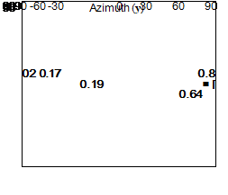 |
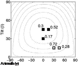
An optimal distribution of panel tilts and azimuth angles was determined for maximization of the fit to annual and summer PV production. The optimization problem was formulated as a constrained minimization problem with the solar fraction calculated from a grid of candidate tilts and azimuth sets with 15 degree intervals. The resulting orientation distributions (cases 1a and 1b) are shown in Figure 1.
Fig. 1. Optimal relative distributions of array orientations for maximization of annual (filled boxes) and
summer (outlined boxes) solar fraction for ALR 2 (left) and ALR 8 (right). Numbers indicate fraction of
systems with the orientation in question. The contour curves indicate annual production relative to the
production at optimal orientation with 5 % steps, starting from 95 %.
Using linear adjustments, the hybrid optical efficiency p0(-) and the thermal losses coefficient U(W/m2°C) were calculated. The thermal losses coefficient is the slope of the thermal efficiency estimated linear behaviour while the optical efficiency is the interception of that line with the yy axis (Fig. 3 and Table 1). The optical efficiency represents the thermal efficiency when there are no thermal losses since the ambient temperature is the same as the average temperature in the thermal receiver.
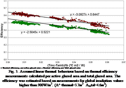 |
Thermal Efficiency G>900W/m2
|
Thermal parameters |
Per active glazed area (Aactive thermal=3.7m ) |
Per total glazed area (Atotal=4.6m2) |
|
По(-) |
0.64 |
0.52 |
|
U(W/m2°C) |
3.1 |
2.5 |
|
Table 1. Measured optical efficiency no(-) and thermal losses coefficient U(W/m2°C). |
The tests at DTI were done outdoors on a side by side configuration with three test panels of 3.5 m2 each and a single PV reference module. PV modules were each 190 Watt from Evergreen.
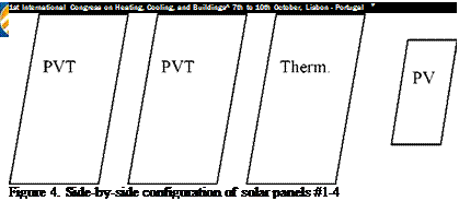 |
System 1: SolarWall with two PV modules on top, variable flow (high)
System 2: SolarWall with two PV modules on top, variable flow (low)
System 3: SolarWall alone, variable flow (thermal reference)
System 4: PV module alone, natural ventilation (electrical reference)
The tests were carried out in open air at variable insolation and wind speed. Side-by-side testing was done to eliminate errors due to different ambient conditions. Nominal flow rates were:
PVT #1: 140 m[3]/h pr m2 PVT #2: 75 m3/h pr m2 T #3: 75 m3/h pr m2
 |
The last PV panel #4 had an open back surface, typical of NOCT test conditions but not typical of an ordinary roof system.
Table 2 indicates the difference in air temperature between ambient and the air leaving the transpired solar panel. Irradiance, wind speed and flow rates are shown to all have an effect on the thermal gain.
|
Table 1. Test Conditions
|
|
Table 2. Air Temperature Rise for various flow rates and PV modules.
|
|
Table 3. Electrical and thermal efficiencies and temperatures
|
The thermal results are interesting in that they clearly show reasonable heat gains and reasonable solar efficiencies. For comparison purposes, the thermal gains of the bare transpired SolarWall panel are shown in Table 2 from the previous certification test data on the same 10 m2 test panel.
Transpired collectors are installed for heating or preheating the ventilation air required in buildings. Most applications are designed to preheat air with a temperature rise in the 5°C to 20°C range. The test data shows that the temperature gain from the PV modules is between 6°C to 20°C or within the typical range for transpired collectors.
It was expected that the bare transpired collector would perform better than with PV modules mounted above it (PV/T). What is surprising is that by resizing the transpired collector or adjusting
the air flow rate, the same thermal design target with PV/T is possible as is currently produced in many transpired collector installations.
The NOCT tests are conducted with an open back and PV suppliers typically list a PV panel temperature in the 47°C range. The PV/T tests, (with a closed back) as listed in Table 3, which is typical of a BIPV configuration, show temperatures similar to or lower than the NOCT data.
The efficiency data for the PV portion of PV/T in Table 3 is based on the dimensions of the PV modules. The thermal efficiency data is based on the transpired collector area of 10 m2. Since the PV modules do not cover 100% of the transpired collector, the column showing Total n (efficiency) is not a straight addition of the PV and thermal numbers but is based on the gross test panel area of 10 m2.
Most of the components to be simulated are already included in the TRNSYS standard library except for the cogeneration unit and the biomass boiler. Hence, new mathematical models have been appropriately written. These models include on one hand operating characteristic curves, on the other hand internal control logics. The characteristic curves have been derived by the elaboration of technical specifications acquired by various manufacturers and they refer to the following ranges of sizes: [70; 500] kWe for gas engine based cogeneration units and [15; 1000] kWth for biomass boilers.
Both the created models implement the following steps:
• Once the nominal heat power has been determined according to the subchapter 3.5, the model calculate left nominal features, e. g. the efficiency and the primary energy consumption at nominal condition;
• Once the mass flow and the temperature of the fluid entering each machine are given as input and a desired outlet temperature is selected, the models calculate the heat required for the stream to reach the set temperature. According to the selected control logic (discrete or continuous modulation), the model identifies the current load rate, the corresponding efficiency and primary energy consumption and the fluid outlet state.
For instance, the algorithm of the cogeneration unit is shortly described.
The first input required by the algorithm is the nominal heat power (Qreq, nom). The corresponding electrical power (Pnom) is determined by:
Pnom = 0.6148Q„ + 0.9282 [kW] (1)
|
The nominal electrical, thermal and first law efficiencies (ne, nom, nth, nom and respectively) are
|
The inlet mass flow and its temperature being known, the model calculates the heat required to heat up the stream to a previously selected temperature. Then, the transferred heat Qcog in [kW] is identified according to the internal control logic (heat load control and continuous modulation). The electrical power Ppart which is related to Qcog can be calculated through the following equation:
О P
^cog = 0.6685-^ + 0.3315 [%] (5)
OP
£^req, nom nom
Afterwards, the electrical efficiency ne, part in [%] corresponding to Ppart is determined according to:
2
For the absorption chiller simulation, the model presented in [4] is used. The characterization of the chiller, in terms of distribution of the heat exchange area between the components and the typical internal flows, is made referring to a commercial chiller. The maximum relative error calculated comparing the model output to the manufacturer performance data does not exceed 10% and it is found for off design conditions (cooling water inlet at 35 °C).
A SCADA system (Supervisory Control And Data Acquisition) is implemented to monitor and supervise the tracking system.
A Supervisory Control and Data Acquisition (SCADA) System is used as an application development tool that enables system integrators to create sophisticated supervisory and control applications for a variety of technological domains, mainly in the industry field. The main feature of a SCADA system is its ability to communicate with control equipment in the field, through the PLC network. As the equipment is monitored and data is recorded, a SCADA application responds according to system logic requirements or operator requests.
In the developed supervisory system the SCADA application manages the overall system dynamics.
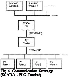
The Communication flux between the supervisory system and the control unit has been already illustrated in fig. 4.
 |
 |
The SCADA PC is simultaneously a SCADA server and an internet server, as the implemented SCADA application is web enabled.
This application permits the selective access to the application depending on the user’s responsibility degree. In this paper we developed three user levels: Operators, Supervisors and Administrators. Among the main functionalities of a SCADA system there is the so called “Tag”.
A “Tag” is a defined variable that permits the change of information between the PLC network and the SCADA system, in a real-time environment. There are usually three types of Tags: PLC, Dummy and Compound. In the PLC Tags the PLC sets the variable values that are directly transferred to the Scada program. In the Dummy Tags the value is set by the user on the Scada interface and transferred to the PLC address. Finally Compound Tags are set by the Scada program, following the programmed operations.
3. Experimental Prototype
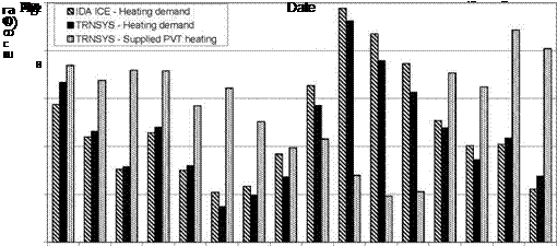 |
The results of these simulations for the selected representative winter period from 16th — 31st July are shown in Figure 3. This graph shows the heating energy of the outlet air from the 16m2 PVT system simulated in TRNSYS compared with the required house heating as modelled using both IDA ICE and TRNSYS. Reasonable correlation is shown between the heating demand results for the house as simulated by IDA ICE and TRNSYS.
Figure 3 shows that on most days during the selected period the supplied PVT heating energy is in excess of the required house heating as modelled in both IDA ICE and TRNSYS. During the 4 day period where the required house heating is greater than that supplied by the PVT system it is expected that the indoor temperature would drop and the degree of this decrease can be seen in Figure 4.

The PVT system integrated into the house was modelled in TRNSYS to determine the resulting indoor zone temperatures when the heated outlet air from the PVT system was directed into the house. The PVT system operated on an input schedule and only delivered heating energy to the building during the colder months from May to August. The resulting indoor temperatures for the house with and without a PVT system are shown in comparison with the ambient air temperature in Figure 4. The running average temperatures for the house and ambient air were calculated by averaging the values over a 20 day period — 10 days before and 10 days after each time point.
Figure 4 illustrates that the heating energy supplied by the PVT system is effective in increasing the indoor air temperature of the well insulated house. The running averages show that the indoor temperature of the house with the PVT system is up to 8°C above the ambient running average temperature during the period from May to August and is also 3°C above the running temperature of the house without a PVT system.
The average running zone temperature presents a promising result in that the temperature does not drop below 20°C. However the simulated indoor house temperature results show that the indoor temperature can drop to a similar temperature level to the house without the PVT system, showing that there is very little heating input during this period. This was also shown in Figure 3. The temperature during this period can drop to 16°C overnight. Despite the thermal mass modelled in the house, the results showed greater than expected daily swings in internal building temperature. This shows that the coupling between the thermal mass and the indoor air could be improved. A method for doing this would be to increase the surface area of the thermal mass inside the zone by
adding thermally massive internal walls to the simulation model to facilitate the exchange of heat with the inside air.
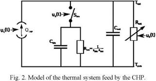 |
The high overall efficiency of cogeneration plants is a result of the simultaneous production of electricity and heat. This effect only is valid if both products can be used. The heat only can be used in the local heat system or stored for a later use. For that reason it is important to model the thermal system. To model the thermal system it is useful to transform the equations into a thermal equivalent circuit (Fig. 2).
The CHP can be seen as a current source QCHP which is modulated control variable ui(t). The fed thermal network is represented by a variable resistance Rnet, which is controlled by u2(t), and a capacity Cnet, which represents the thermal capacity by changing the temperature level in the allowed range. The usage of the thermal storage is necessary if Cnet is used completely and the CHP should operate anyway, e. g. in case of high feed-in tariffs. The switch Ssto, controlled by u3(t), represents the valve regulating the liquid flow through the storage. The storage is modelled as a capacity Csto and a parallel resistance Rsto = k 1Arepresenting the heat losses to the ambience. The thermal conductivity is given
by kstoAsto. In this model all temperatures are referred to the ambient Tamb. This also can be written as differential equation:
The three input variables u1(t), u2(t), u3(t) define the output of system described before. It is assumed that Thot stays above 60 °C. For the simulation the thermal demand is given as a time series and defines u3(t). In the showcase it is not possible to modulate the CHP, so u1(t) can have the discrete values 0 and 1. To optimise the operation of the CHP the best relation of u1(t) and u3(t) according objective function must be evaluated. The target of the system operator is to minimise his operation costs. It is assumed that the CHP can fed into the electricity grid with a variable tariff cel(t) anytime. This directly influences the operation costs c(t) of the system. Neglecting heat storage losses, the operation costs depend on the feed-in tariff cel(t) and the fuel costs cfuel. The objective function can be defined as:
Jc(t) = J u Шшр [иеі -4elcd (t)]= mm (2)
t t nth
The used primary energy can be calculated with the thermal efficiency nth of the CHP. The variable nth/hei defines the ratio between produced heat and electricity. Nonlinear relations like the discrete operation of the CHP, the given time series for cel(t) and the thermal demand make an analytic solving very complex. To reduce the complexity we made linear approximations and transformed the problem to a mixed integer linear problem MILP [4]. These kinds of problems have got the advantage that their performance still with a high number of variables is very good. There are also efficient solvers with the Simplex algorithm available [5].
3.1. Canadian Tests
The tests were performed over a two week period in October 2006 and the results are summarized in the following tables. Table 1 lists the two primary test conditions, #1 for NOCT test conditions typical of PV systems and #2 for test conditions typical of solar air collectors. The heat was drawn off at two rates, 36 and 108 m3/h. m2 (2 and 6 cfm/ft2) of collector surface and results are shown separately for each flow rate.
[2] Introduction
Hybrid Photovoltaic/Thermal (PV/T) collectors are devices that simultaneously convert solar energy into electricity and heat. The reason behind the concept of hybrid PV/T is only 6-15% (depending on the cell type and technology) of solar radiation converted into electricity by solar cell. The remaining energy is converted into heat which caused increased the solar cell temperature that will affect decreasing the solar cell efficiency. There are several reasons to combine Photovoltaic (PV) and Solar Thermal Collector into one PVT device which are larger overall conversion efficiency, reduced energy payback time, reduce economic payback time and improved aesthetics. Cooling the solar cell with working fluid like water and air will increase the solar cell efficiency. There are two ways to cool the PV/T, which are cooling by water and cooling by air. Cooling by water can be applied to produce hot water and cooling by air can be utilized for space heating application. Based on those facts, PV/T will be the ideal solution in the higher environmental temperature and also to keep long life the Solar Cell.
A Typical model of PV/T is the direct attachment of PV modules onto a solar collector surface. Per unit area the total efficiency of a PV/T panel is higher than the sum of the efficiencies of separate PV
[3] Rabl, A., (1985). Active Solar Collectors and Their Application, Oxford University. Press, Inc. New York
[4] Results and discussion
The results from HOMER show that for a load of 6000 kWh with a capacity shortage allowance of 10% and a hub height of 20 m not for all locations a feasible system is possible (Figure 3). For the load of 6000 kWh no feasible systems were found for the locations with the two highest latitudes. For loads of 3300 kWh and 1800kWh for all locations feasible systems were found. The NPC varies between $48,000 and $87,000 for the highest load and $17,000 and $33,000 for the lowest load. It is obvious that energy saving measures would a cost effective alternative instead of enlarging the system size.
[5] Introduction
The overall problem with the use of PV-systems is the high cost of the solar cells. This makes it appealing to concentrate irradiation on the PV module in order to minimise the required PV-area for the same output. With increased light concentration, there will be a demand of increased cooling on the PV cells in order to lower the working temperature preventing damages and maintaining cell efficiency. Solar8 is a photovoltaic/thermal parabolic concentrating system that tracks and concentrates light into a water cooled photovoltaic module working as a thermal absorber. By using the heat generated in the absorber, the photovoltaic/thermal device (PVT) generates not only electrical, but also thermal energy (Fig. 1). The photovoltaic module is formed by two sections, each one with 32 cells. These sections can be connected both in series and parallel. Generally, a concentrating system with a large number of series connected cells like Solar8 is highly sensitive of local defects in the optical system and on the solar cells, supposed to receive an equal amount of irradiation. The total electric