Как выбрать гостиницу для кошек
14 декабря, 2021
Сегодня каждый, кто собирается в отпуск и не знает, с кем оставить своего котика или кошку, может во[...]
E. Ampatzi[5]*, I. Knight1, M. Rhodes1 and F. Agyenim1
1 Welsh School of Architecture, Cardiff University.
* Corresponding Author, AmpatziE@cf. ac. uk
Abstract
This paper investigates the applicability of solar thermal systems for domestic hot water preparation and thermal comfort satisfaction across the Welsh housing stock. It analyses the role of thermal energy storage technologies (TES) in achieving significant solar fractions with these systems.
Twelve house types, considered as representative of the entire Welsh Housing stock are modelled and the thermal energy demand for space heating and cooling and domestic hot water preparation for each house type is calculated. The share of the total thermal energy requirement that can be met by solar energy, instantaneously and by means of thermal energy storage techniques for each house type is predicted. The results of this work reveal the relative importance of the use of TES in solar thermal applications for the climate of Cardiff and the specific housing types. The analysis will show for each house type the trade off between storage capacity and collector’s area, to achieve solar fractions of 50%. The effect of warmer than average weather conditions is also revealed, with the use of actual measurements of year 2007 for the city of Cardiff.
Keywords: Thermal Energy storage, space heating and cooling, DHW, TRNSYS.
The high density of storage with chemical reactions makes the topic attractive. However many difficulties must be overcome to get to a commercial solution. The choice of an adequate reaction has kept attention at ECN, The Netherlands. A promising material is magnesium hydroxide seven hydrates which could theoretically store 777 kWh/m3 at 122 C.
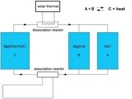 Fig. 13. Sketch of a future chemical heat store system with its three vessels, at ECN, the Netherlands (for a 12.2 MWh capacity, tanks volume could be: A 14 m3, B 5 m3, C 16 m3)/
![]() This is a temperature that high performance solar collectors can achieve in summer time. The principle is to dry the material in summer with solar heat and in wintertime rehydratation can deliver back the energy (figure 13). Work with this material and its abitlity to de-hydrate and re-hydrate has just started.
This is a temperature that high performance solar collectors can achieve in summer time. The principle is to dry the material in summer with solar heat and in wintertime rehydratation can deliver back the energy (figure 13). Work with this material and its abitlity to de-hydrate and re-hydrate has just started.
Harald Mehling*, Stefan Hiebler, Christian Schweigler, Christian Keil, Martin Helm
Bavarian Center of Applied Energy Research (ZAE Bayem), Walther-MeiBner-Str.6, 85748 Garching,
Germany
* ph:++49 89 329442-22, fax: :++49 89 329442-12, e-mail: Mehling@muc. zae-bayern. de
In solar thermal installations, full annual utilisation is desirable. This can be achieved with solar space heating during the cold season and solar cooling by means of sorption cooling in the warm season. When low temperature heating and cooling facilities like floor or wall heating systems or activated ceilings are applied for heating and cooling, a low-temperature heat storage using the latent heat of phase change materials (PCM) can be used to significantly improve the system in the cooling and also in the heating mode. After completion of tests on functional models, a full scale storage with about 2 tonnes of CaCl26H2O as PCM and capillary tubes as heat exchanger was built in fall 2006. The storage consists of two modules with a total volume of 1.5 m3 and has a design storage capacity of 120 kWh in the temperature range from 25 °C to 33 °C. At first, the performance of the storage was determined in standalone tests. Then, the storage was integrated into the new system for solar heating and cooling at the ZAE Bayern. This paper reports on the stand alone tests, and the tests performed after the storage was integrated into the system during summer operation in 2007 and winter operation 2007/2008.
Keywords: latent heat storage, solar cooling, absorption chiller, phase change
In solar thermal installations with large capacity, full annual utilisation is desirable. During the cold season, solar heat serves for space heating. During the warm season, solar heat can be converted into useful cold by means of sorption cooling. A favourable situation is given when low temperature heating and cooling facilities like floor or wall heating systems, or activated ceilings, are applied for heating and cooling. In that case a low-temperature heat storage using the latent heat of phase change materials (PCM) can be used to significantly improve the system in the heating and also in the cooling mode. In the heating mode the heat storage is used to level the highly variable solar gain. In the cooling mode the storage is used to reject waste heat in combination with a dry cooling tower, instead of using a wet cooling tower. To allow the use of a single storage in the heating mode as well as in the cooling mode to reject waste heat, the heat has to be stored in a very narrow temperature range around 30 °C.
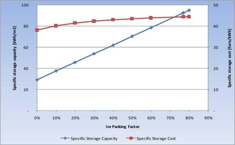
The results of this analysis are best summarized in Fig.1 below. This figure shows the specific storage capacity [kWh/m3], as well as the specific storage cost [Euro/kWh stored heat], as a function of the ice packing factor (that is, the volume fraction of PCM in the storage). Zero percent IPF is thus equivalent to a conventional stratified water storage. This particular case is assuming a AT for storage of 25 °C.
As shown, when considering the capital (first) cost only, the cost of the PCM-storage is always higher than for a water storage (see IPF=0) although the difference is not very large. However, if the cost of “space requirement” is important, such as in a house, the PCM — solution quickly becomes cost
|
Fig. 1. A comparison of a PCM thermal energy storage (IPF>0) to a conventional hot water storage (IPF=0) with regards to specific storage capacity (diamonds) and cost (squares). |
effective as compared to the hot water storage. Assuming a cost of space of 300 Euro/m3, the specific storage cost levels off at just below 48 Euro/kWh regardless of IPF such that the cost of a PCM storage is the same as that of a conventional stratified water storage. Then the advantage of the PCM storage is clear — approximately one third the space requirement as compared to a water storage.
Fig. 1. also shows that one important attribute affecting the specific storage capacity is of course the Ice Packing Factor so that designing a PCM storage with as high an IPF as possible is good for the technical competitiveness of this technology option for storage. As the IPF increases, the cost- effectiveness of the PCM-storage is also likely to be enhanced. This finding was taken into account when designing the storage prototype presented below.
F. Ochs1*, J. NuBbicker-Lux1, R. Marx1, H. Koch2, W. Heidemann1, H. MBller-Steinhagen1, 3
1 Institute of Thermodynamics and Thermal Engineering, Pfaffenwaldring 6, 70569 Stuttgart, Germany
2 Pfeil und Koch Ingenieurgesellschaft mbH PKi, Stuttgart, Germany
3 DLR Stuttgart, Institute of Technical Thermodynamics
* Corresponding Author, email: ochs@itw. uni-stuttgart. de
Abstract
The solar assisted district heating system with seasonal thermal energy storage in Eggenstein-Leopoldshafen (Germany) is the first system realized with existing renovated buildings. The system consists of 1600 m2 flat plate collectors and a 4500 m3 gravel-water thermal energy store (TES) for seasonal thermal storage. Experiences gained within the BMU-project “Further development of the pit heat store technology” contributed to the design of the seasonal TES. This paper focuses on the design and construction of the gravel — water store. The monitoring concept of the solar assisted district heating system with focus on the gravel-water TES is presented.
Two different cubicles were built:
1. Reference cubicle: The alveolar brick has an especial design which provides both thermal and acoustic insulation. No additional insulation was used in this cubicle.
2. PCM cubicle: Several CSM panels (Fig. 3) containing SP-25 A8 hydrate salt are located inside the cubicle, between the alveolar brick and the plaster plastering in order to increase the thermal inertia of the wall (in the southern and western walls and the roof).
|
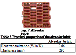
Fig. 7 Alveolar brick. |
|
Table 3 Physical properties of the alveolar brick.
|
|
Table 4 Physical properties of SP-25 A8.
|
 |
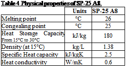 |
Fig. 7 presents the alveolar brick. The most important properties of the alveolar brick and SP-25 A8 are shown in Table 3 and Table 4.
|
Fig. 8 Demonstration cubicles built with alveolar brick. |
Fig. 8 shows the demonstration cubicles built with alveolar brick.
1.1. Instrumentation and registered data
To evaluate the insulating performance of each material the following data were registered for each cubicle.
• Wall temperature (east, west, north, south internal, south external, roof and floor).
• Internal ambient temperature (1.5 m) and humidity.
• Heat flux at the south wall (inlet and outlet).
• Electrical consumption of the heat pump.
• Solar radiation.
• External ambient temperature and humidity.
1.2. Experiments performed
The experimental set-up offers the possibility to perform two kinds of tests.
• Free-floating temperature, where no heating/cooling system is used. The temperature conditions in the cubicles are compared. The ones with PCM are expected to present a better behavior.
• Controlled temperature, where a heat pump is used to set the ambient temperature of the cubicle. The energy consumption of the cubicles is compared using different set points. The cubicles using PCM are expected to present lower consumptions.
3.1. Passive and active thermal storage in the house
Simulations indicate that during a clear sunny or even a partially sunny day, no heating will be required [1]. The main challenge of the control strategy thus consists of gathering as much thermal energy as possible during sunny days, and storing it so that it can be used over a sequence of cloudy days (at least 2 days), thus minimising the use of the backup (i. e., the ground source). The many systems of this house make controlling it a challenging task. However, despite the inherent complexity of the problem, the key issue is the rational balance of the two thermal storage media for stockpiling solar thermal energy: the passive thermal storage in the building’s structure thermal capacity (mainly in the floor slab and the masonry wall) and the active thermal storage (TES tank).
The passive storage of the ANZEH is charged by the solar heat gains obtained through the windows (which are practically an essential component of the heating system) and by the radiant floor heating pipes. The passive storage is discharged when it gives heat to the indoor space. Naturally, this thermal energy is eventually released to the surroundings of the house. The TES reservoir (active storage) can be charged in four ways: (a) through the direct recovery of thermal energy from the BIPV/T air, via the HX; (b) with one or both HPs using the BIPV/T air; (c) with the HPs, but using the ground as the heat source; and (d) with excess energy from the solar collector loop. The TES is discharged mainly by its use as a source for the radiant floor heating system; it is also discharged by delivering thermal energy to the DHW tank and through natural heat losses to the surroundings.
The following considerations should be addressed in the design of the control strategy:
• Although temperature fluctuations are needed to take advantage of the thermal mass potential for storing thermal energy, comfortable indoor conditions must be maintained at all times.
• These temperature fluctuations occur at time scales of several hours, much longer than the time constants of the sensors and of the HVAC system.
• The COP of the HP(s), and thus the energy delivered to the TES, depends mainly on the temperatures of the BIPV/T air and the bottom of the TES tank. The COP also depends on the water flow rates on both sides of the HP(s), and the air flow rate through the HX.
• The thermal energy stored in the tank increases with its temperature. Since the COP of the HP(s) decreases as the temperature of the tank increases, the decision to charge the tank should be made based on the availability of thermal energy at the present time and in the future.
|
Q |
|
(8) |
|
AT Ztotal |
The closed two-phase thermosyphon is an effective heat transfer device. The working principle can be easily explained as obtaining heat from the evaporator section by means of the evaporating mechanism and then releasing the heat out of the condenser section by means of the condensing phenomena. Because the latent heat of vaporization of the working fluid is relatively high, a large amount of heat can be transported through the thermosyphon.
where AT is the effective temperature difference between the heat source and the heat sink
|
(9) |
![]() AT = Tso — Tsi — ATh
AT = Tso — Tsi — ATh
|
ATh = ‘ p |
|
(Tp — Tv)x F |
|
(10) |
Where Tso is the heat source temperature,(oC), Tsi is the heat sink temperature,(oC) and the mean temperature difference due to hydrostatic head, ATh is given by
|
Where the saturation temperature at the bottom of the pool, Tp is given by |
P v |
|
(11) |
|
dH L |
|
(12) |
|
Tv — Tsi + |
|
^ Z7 + Z8 + Z9 (t _ T ) so si |
|
total |
|
(13) |
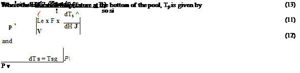 |
For the vapor temperature of the working fluid, Tv is determined from
Where Ztotal is the overall thermal resistance of the thermosyphons, it can be represented by the idealized network of thermal resistances Z1 to Z10 as shown in Figure 4.
|
Z1 M+MV |
![]()
|
Z9 |
![]()
|
Z10 |
![]()
|
Z4 |
![]()
|
Z5 |
![]()
|
AV |
![]() z1,z9 Convection z2,z8 Convection z3,z7 Internal resistance
z1,z9 Convection z2,z8 Convection z3,z7 Internal resistance
of boiling & condensing z5 Pressure drop
z10 Thermal conduction
resistance axially z4,z6 Vapor-Liquid internal
|
Z3f |
|
t Z3p ► Z2 |
|
Condensate |
|
AV |
|
Z10 |
|
Z1 |
|
Z9 |
Z6
Fig 4.Thermal resistance and their locations.
2.1. Welsh Housing Stock Survey (STACS)
The housing types used in this study are drawn from generic housing data for Wales taken from the STACS project [2]. This selection is believed to give a good approximation of the entire Welsh Housing Stock. Materials and geometry data for the 12 dwellings shown in Table 1 are provided by the survey. For the purposes of this study the 12 types are treated as representative case studies and the results are considered indicative for the entire housing stock of Wales.
|
Table i. typical dwellings of Wales (STACS)
|
The actual orientation of each house is used and for the overshadowing assessment, the impact of the volumes of the building itself and of the buildings attached to it (e. g. if semi-detached or midterrace) are only taken into account, ignoring other neighbouring buildings and vegetation.
2.2. Software
For the simulations conducted in this study, the software package TRNSYS (version 16.01.0002) is used [3]. The software has a modular structure with a main visual interface known as the TRNSYS Simulation Studio. There is also a dedicated interface for the multizone building component (TRNBuild) which is one of the most complex models in TRNSYS. The building component of TRNSYS has undergone testing under the ANSI/ASHRAE Standard 140 and IEA BESTEST with acceptable results. Validation tools have been also used during the development of the software [4,5]. In addition the software Ecotect [6] is used as a front-end for the building modelling and for certain stages of the analysis as described below. Ecotect is is a complete building design and environmental analysis tool with a very advanced and user-friendly 3D interface.
Several criteria can be considered for comparing storage technologies. Task 32 of IEA SHC prepared a detailed list. The first indicator concerns the energy performance of a combisystem with the storage technology. The value of Fsav the fractionnal energy saving has been selected as the best indicator and can be derived from the parameter FSC’.
FSC’ is a dimensionless quantity simultaneously taking into account the climate, the building (space heating and domestic hot water loads) and the size of the collector area, in a way that doesn’t depend on the studied combisystem. First developed within IEA SHC Task 26 [2], the FSC (Fractional Solar Consumption) has been improved in Task 32 to yield to FSC’ which takes into account a possible cooling load also, and the ability of a store to be seasonal.
This means that it has been possible to show that Fsav is a function of FSC’ even if FSC’ is greater than 1.
Energy performance indicators
NRJ1 Fractional energy savings Fsav as a function of FSC’
NRJ2 Comfort for heating and DHW load met without penalties
NRJ3 Comfort in cooling conditions
NRJ4.1 Heat storage material energy density kWh/m3
N RJ4.2 Bulk storage density kWh/m3
NRJ4.3 Storage efficiency
Economical indicators
ECON1 Investment cost per kWh stored
ECON2 Operational costs per kWh discharged
Market introduction
MKT 1 1 if on the market, 2 if within 3 years, 3 in more than 3 years
Environmental indicators
ENV1 Storage material risk (corrosion + toxicity + safety)
ENV2 CO2 saved by the system compared to a reference System integration
INT1 weight of material for the storage unit kg/kWh capacity
INT2 number of separate pieces
INT3 level of skills required to install the storage unit
INT4 need for technical maintenance
Table 1. Criteria considered for comparison of heat storage units within Task 32
In order to assess Fsav in comparable conditions it is necessary to set up a standard simulation framework that many different systems can use. Task 32 defined a complete set of parameters for TRNSYS simulations, for 3 different reference houses (a low energy house with only 30 kWh/m2 for
space heating, 60 and 100 kWh/m2) in 4 different climates (Stockholm ,Ztirich, Barcelona, Madrid). The entire deck of parameters is available through IEA SHC.
Storage technologies integrated into a solar combisystem can be compared using this new method.
Water is still the storage of choice for solar combisystems for the years to come. Some important findings for other materials have been discovered by Task 32. Models are now available for more optimisation analysis and for defining the best material a combisystem would need.
Several technologies for advanced storage concepts have been tested within Task 32. Table 2 summarizes them and their status at the end of 2007.
Future work on new materials for heat storage is important since we discover the limits of some promising components.
A new IEA Task will continue the work Task 32 has initiated, but will be more focused on material research.
Solar energy need a dense and long term storage solution if it is to used intensively for house heating.
References
[1] Hadorn J.-C. editor, (June 2005), Thermal energy storage for solar and low energy buildings — State of the Art, a IEA SHC Task 32 book, Printed by Servei de Publicacions Universidad Lleida, Spain, 170 pages ISBN 84-8409-877-X, available through Internet www. iea-shc. org Task32
[2] IEA SHC Task 26 (2004): Solar Heating Systems for Houses — A Design Handbook for Solar Combisystems, W. Weiss and al., James & James, 2004, 313 pages
[3] Task 32 reports are available at http://www. iea-shc. org/task32/publications/index. html
|
Principle |
Material |
Institute |
Status 2007 |
|
Chemical reactions |
|||
|
Closed 2 phase absorption |
Mg SO4 7H20 |
ECN The Netherlands |
Material investigation |
|
Sorption |
|||
|
Open adsorption |
Zeolite solid |
ITW Germany |
Laboratory unit |
|
Closed adsorption |
Silica gel particles in bed |
AEE Austria |
System in a house tested — stopped |
|
Closed adsorption |
Silica gel and Zeolite beds |
SPF Switzerland |
Material and bed tested — stopped |
|
Closed 2 phase absorption |
NaOH / H2O |
EMPA Switzerland |
Laboratory unit runing |
|
Closed 3 phase absorption |
LiCl |
SERC Sweden |
commercial |
|
PCM |
|||
|
PCM seasonal storage using subcooling |
Na(CH3COO)3 H2O |
DTU Denmark |
Simulation of concept — Prototype 135 liters |
|
Macroencapsulated PCM in storage tank |
Na(CH3COO)3 H2O + graphite |
Univ. Lleida, Spain |
Lab prototype |
|
Macroencapsulated PCM in storage tank with integrated burner |
Na(CH3COO)3 H2O + graphite |
HEIG-VD Switzerland |
Complete combisystem tested |
|
Microencapsluated PCM slurry |
Paraffin, |
IWT-TUGraz Austria |
Lab prototypes — Stopped for storage |
|
Macroencapsulated PCM in storage tank |
Paraffine, Na(CH3COO)3 H2O with/without graphite |
IWT-TUGraz Austria |
Lab prototypes |
|
Immersed heat exchanger in PCM |
Na(CH3COO)3 H2O without graphite |
IWT-TUGraz Austria |
Lab prototypes |
|
Water |
|||
|
Simplified combisystem Maxlan system |
Water |
SPF Switzerland |
Simulation proved |
|
Water Stratifier |
Fabrics immersed in water |
DTU Denmark |
Laboratory proved |
|
Table 2. Storage technologies that IEA Task 32 has investigated between 2003 and 2007 |
![]()