Как выбрать гостиницу для кошек
14 декабря, 2021
Сегодня каждый, кто собирается в отпуск и не знает, с кем оставить своего котика или кошку, может во[...]
The collector considered in this study is a Direct Flow evacuated tube collector [17] which is part of a physical research programme by the authors. The gross area of each collector unit is 4.245 m2 (1.996m*2.127m L/W) and the absorber area per unit is 3.02m2.
Using the maximum number of these units that can be physically accommodated within the boundaries of each roof, the potential collectors’ yield for each house is calculated and shown in Table 5. This yield clearly depends on the geometry of the house i. e. roofs’ size, orientations and overshadowing as mentioned in 2.1. For flats 9 and 12 the total roof area of the building is assumed to be available for use of these flats (top floor flats). For flats 5 and 12 it is unknown what share of the building’s roof or terrace could be used, therefore only vertical collectors are assumed to be mounted on external walls. For the houses all the roof areas (except those facing north) are considered to be used and no vertical external surfaces are used. A significant part of these roof surfaces are not covered by collectors, due to the fact that the specific collector type comes in a standard size.
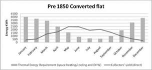
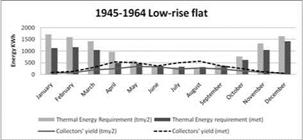
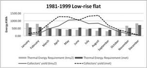
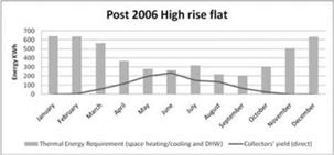
Figure 3 contains 12 graphs, one for each of the 12 houses modelled, showing the monthly thermal energy requirement in relation to the monthly collectors’ yield. All graphs show predictions using the tmy2 weather data. On two of the houses (with the highest and lowest demands) the predicted demands with the actual weather data of year 2007 are compared to those with the tmy2. Year 2007 was a significantly warmer year than average for Cardiff and therefore the predicted space heating demand is much lower than average and the solar thermal energy availability calculated with this data is much higher. This comparison reveals a much larger potential for solar thermal as average temperatures increase.
|
Table 5. Number of potential collector units, roof tilts and azimuths, and total collectors’ yield
|
The main findings of the studies on open adsorption storage designed for seasonal storage of solar heat, as reported by ITW in Germany, are the following:
• An effective sorption storage integrated in a conventional mechanical ventilation system has been developed in the Institute of Thermodynamics and Thermal Engineering (ITW), University of Stuttgart and was theoretical and experimental investigated
• For the first time, highly filled zeolite honeycomb structures made by extrusion of zeolite powder using thermoplastic polymers as plasticising aid and binder are used as adsorbent. Honeycomb structures have decisive advantages compared with fixed beds of spheres or other shaped bodies. They show excellent adsorption kinetics and generate low pressure losses along the process length. In open cycle processes low pressure drop is important to minimise the electric power consumption of the fans.
• Theoretical analysis has been carried out. Special attention has been given to precisely incorporate the appropriate physical and chemical processes that occur during adsorption and desorption, into the theoretical model; this will then reflect the proper performance of the proposed sorption system under real practical conditions.
• Simulation of the space heating for a residential building based on sorption storage was carried out using TRNSYS. The sorption process was evaluated using a 1-D two-phase model with heat — and mass-balance in a separate numerical routine.
• A prototype sorption storage tank integrated into a commercially available residential heating system has been built at ITW. The system has been scaled to achieve short cycles on a weekly basis, so that the system could be tested under varying conditions.
• Theoretical analysis shows that, compared to the adsorption period, the desorption process is more sensitive to several input parameters.
• Experiments have been carried out that demonstrate the technical feasibility of the proposed system under real operating condition. The experimental results concerning the thermal behaviour of the adsorption/desorption process and the achieved heat storage capacity are in good agreement with the theoretical analyses. Furthermore it has been shown that the solar thermal desorption
conditions using high performance CPC collectors performs well. Special attention was given to achieve the necessary high desorption temperature of 180°C inside the sorption store.
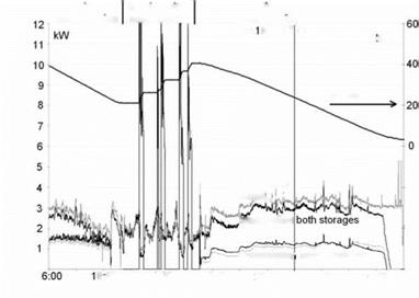
Fig. 8. shows the typical heating power and stored heat on a day in fall. On sunny days, the storage can be fully loaded. However, most days, as shown in fig. 8, the storage is only partly loaded. In daytime the total energy demand of the building is rather low, therefore the solar heat must be stored and used in night time. At night time the storage almost completely covers the heating power demand (fig. 8), unless the night time outside temperatures are extremely low. In that case the auxiliary heater is used. During the heating period 2007 / 2008 a significant increase of the solar gain in the system has been observed; this is due to the low temperatures using the LHS.
|
Table 3. Solar fraction of the heating demand.
The solar heat stored in the latent heat storage covered up to 72 % of the heat demand (tab. 3). If the latent heat storage was fully loaded, excess solar heat was stored in the hot water heat storage. Both storages in combination covered almost 100 % of the heating demand. |
|
heating power demand;.,. * |
|
space heating |
|
Oct. 9.2007 |
|
Oct.20.2007 |
|
|||||
|
|||||
|
|||||
|
|||||
|
|||||
|
|||||
|
|
|
|||
|
|
||||
time
Fig. 8. Typical heating power and stored heat on a day in fall.
The storage is now installed and used in the system for one and a half years. During that period, a total of over 250 charge and discharge cycles of the storage were completed. About every two months, a separate cycle just to test the storage is performed. These tests have shown no degradation of the storage capacity or storage power.
As part of a demonstration project a pilot installation of a solar heating and cooling system was installed in the R&D building of the ZAE Bayern in Garching. The system includes a latent heat storage that stores about 120 kWh in the temperature range from 25 °C to 33 °C. As PCM, 2 t of CaCl26H2O melting at 28-29 °C are used. Stand-alone tests of the storage showed that it fulfils the designed heat storage capacity and power. First operational results of the system since summer 2007 confirm the general feasibility and the design of the system. During the heating season, the latent heat storage allows a low operating temperature of the solar collectors thereby increasing the solar gain. In the cooling season, the latent heat storage supports the heat rejection of the absorption chiller. Analysis of system operation and performance will continue until end of 2009.
The project is supported by funds of the German Federal Ministry of Environment (BMU) under contract number 0329605D.
[1] H. Mehling, S. Hiebler, C. Schweigler, C. Keil, Development of a Latent Heat Storage for a Solar Heating and Cooling System, Proceedings EUROSUN 2006
[2] Schweigler, C., Hiebler, S., Keil, C., Kobel, H., Kren, C., Mehling, H.: Low temperature Heat Storage for Solar Heating and Cooling Applications. ASHRAE Transactions, ASHRAE Winter-Meeting, 2007
[3] M. Helm, B. Potz, C. Keil, S. Hiebler, H. Mehling, C. Schweigler, Solar heating and cooling system with low temperature latent heat storage — energetic performance and operational experience, International Sorption Heat Pump Conference 2008, 23-26 September, 2008, Seoul, KOREA
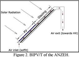
Perhaps the most novel feature of the house is its Building Integrated Photovoltaic/Thermal (BIPV/T) roof, and the solar heating system based upon it. This roof has an array of polycrystalline photovoltaic panels mounted on a commercial photovoltaic framing system designed for roof installations. The peak capacity of the PV, 5.5 kWp in the first design, was increased to 7 kWp to provide energy to a plug-in hybrid vehicle. As in many roofing systems, in this framing structure each frame slightly overlaps the one located below. This is significant, as these PV panels, which occupy 55% of the total area of the roof (105 m2), are not used only for generating electric power: they also play an important role as part of the building envelope by replacing asphalt shingles. The roof has a 45° slope (roughly equal to Montreal’s latitude) and due south azimuth orientation.
|
|
An air inlet under the soffit permits the use of a variable-speed fan to draw exterior air through a gap under the PV arrays. This system allows for the recovery of useful heat from the roof and has the additional advantage of lowering the temperature of the PV panels. For a system such as that in the ANZEH, this represents additional electric power on the order of hundreds of watts, which might partially or totally offset the energy consumed by the fan. A glazing section filling the remaining area of the roof above the PV panels helps to increase the temperature of the BIPV/T air. The glass panes are mounted on the same framing system used by the PV arrays. Below the glazing section, a low-emissivity absorber surface enhances the recovery of solar thermal energy. The air temperature rise depends on several factors, the most important being solar radiation, exterior temperature, air flow rate and wind speed. For a clear sunny day during a Montreal winter and a flow rate of about 450 L/s, the air temperature rise may exceed 40 °C. As the stagnation temperatures of the BIPV/T system can be quite high during the summer (up to 100°C) a small fan will be used to remove hot air from under the roof through an opening on the east side of the roof. A manifold located at the rooftop connects the BIPV/T roof to a ducting system. The ducting system has been designed to minimize the pressure drop and therefore the power requirements of the variable-speed fan (with a maximum power of about 500 W).
• The residential building offers 8 apartments (3 x 4.5 rooms, 3 x 5.5 rooms, 2 x 2.5 rooms) and is situated in Oberburg, Switzerland.
• To reach optimal solar efficiency the building is orientated towards the south.
• In the 276 m2 sized collector field the water will be heated and later stored in a 205’000 l seasonable hot water tank. In addition to this innovative heating system the building disposes of a above average heat insulation and well insulated windows for passive sun energy generation.
• Because of the size of the tank (17 m height, 4 m diameter), it was installed after the foundation was laid, and then the rest of the building was constructed around it.
• Construction costs: ca. 2 Million Euros (excluding land). Investment for solar system is less than 10 % of overall construction costs.
• The rental price of the eight apartments is average for the area.
At University of Zaragoza, there is an experimental setup to study the heat transfer between PCM and air (Figure 1). The experimental rig consists of a closed air loop with a storage unit. The air in the loop can be heated and cooled artificially. A PID controller regulates the inlet air temperature in the storage unit. The temperature of the air is measured at the entrance and exit of the storage, using five calibrated Pt100 (uncertainties < 0.05 °C) in each point; air flow is measured using a calibrated flowmeter (uncertainty <0.5%). All data are stored and evaluated with tailor-made software [12].
With this setup, heat capacity as a function of temperature in big samples could be estimated. It is used to evaluate the effect on energy storage capability caused by the addition of PCM.
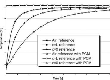
By modifying this rig, it could be used to study thermal response of building materials. This modification consists on building an insulated enclosure where sample is placed so that only one surface is exposed to the air flow. Air flow is then bypassed (Figure 2). Temperature is measured at three points: centre of insulated surface, centre of exposed surface and air temperature at centre of exposed surface. Air temperature is maintained constant by a PID controller. Air flow is measured and set at the same rate for all experiments. Temperatures are registered and then could be compared its evolution for different samples in equal conditions. In order to evaluate thermal response time effect due to PCM, a reference without PCM is used. Then, the sample containing PCM is measured in equal conditions (initial temperature of the samples, airflow rate and air temperature).
|
Figure 2: Energy Balance configuration to test thermal diffusivity |
|
Figure 1: Energy Balance setup to measure stored energy as a function of time and to study heat transfer between PCM and air. |
x=0, T2 x=L, T1
Figure 3 shows an example of comparison of temperature evolution between sample containing PCM and reference. Some results are presented in this conference [13].
|
Figure 3: typical temperature evolution comparison of reference and reference containing PCM samples. |
Fig. 1 shows the typical arrangement for plates of PCM separated by a gap in which the heat transfer fluid passes. As the fluid flows along the plate heat is convected between the fluid and the PCM plate, and phase change occurs. This phase change occurs in both the x and y direction. An experimentally validated two dimensional model of a plate with PCM has been developed [5]. The model demonstrated that this phase change begins at the upstream top corner of the slab (Fig. 2). As this process continues the top layer of the plate changes phase first since it is in direct contact with the wall where the resistance is least. As the process continues, this solid/liquid line continues to progress down through the plate. Furthermore, this line has a slight incline, such that the thickness of the section which has changed phase is greater at the upstream end of the slab.
In addition to this process the plate is changing phase in the direction of the flow path. The largest driving force exists at the inlet, where the difference between the fluid temperature and phase change temperature is maximum. Due to this driving force, a solid/liquid front begins at the upstream face of the plate. Once phase change of an initial section of the plate has been complete, the temperature of
|
Fig. 2. Section of PCM slab showing solid/liquid front during phase change. (Courtesy of [5]) |
|
y |
![Подпись: Fig. 2. Section of PCM slab showing solid/liquid front during phase change. (Courtesy of [5])](/img/1128/image314.gif) |
|
the PCM within this section approaches the inlet fluid temperature reducing heat transfer. As a result, the maximum driving force occurs further downstream at the next section of the plate. Consequently a vertical solid/liquid line moves down the length of the plate during the phase change process. In essence, the PCM begins to change phase at the top upstream corner of the plate and ends at the centre of the downstream face of the plate (Fig.2). The assumed location of the solid/liquid front in both [2] and [3] is inconsistent with this result.
The thermal resistance is a function of the overall heat transfer coefficient between the fluid and PCM, and the heat transfer area. Fig. 2 shows that the solid/liquid line moves both the x and y direction, and therefore both the heat transfer area and the overall heat transfer coefficient change with time. Since the dominant direction of the front is along the x and y axis, it is proposed that this front can be approximated by a rectangular profile (Fig. 3). By assuming that the front is defined by a rectangular profile, the heat transfer can be treated as a one dimensional process and defined by a single thermal resistance. This thermal resistance can be characterised by an overall heat transfer coefficient and a heat transfer area, as defined by Eqn. (1), both of which change with time.
|
Fluid flow |
|
Heat transfer wall |
|
Fig. 3. Approximation of solid/liquid front during phase change. |
|
RT =• |
![]() 1
1
UA
|
(1) |
![]() U = 1 + У h k A = xW
U = 1 + У h k A = xW
The equation for the overall heat transfer coefficient ignores the axial heat conduction. As described in [2], given the low thermal conductivity of the PCM axial heat flow is negligible. As found in [5], natural convection is also ignored due to the small slab thicknesses used.
In practice a PCM storage system can be described as a heat exchanger in which the heat transfer fluid exchanges heat with the PCM at the phase change temperature. The performance of a heat exchanger is described by the heat exchange effectiveness. The effectiveness equates to the ratio of the actual heat transfer to maximum possible heat transfer, which is defined by the maximum temperature difference between the heat transfer fluids. A PCM storage system can also be characterised by its effectiveness, defined by Eqn. (2), [6]. Therefore maximum effectiveness of unity occurs when the heat transfer fluid exits at a temperature equal to the phase change temperature. Effectiveness is a useful parameter from a design perspective. In an application of a TSU with PCM, the outlet temperature during the discharging process must meet system specifications. Therefore, the minimum effectiveness can be found after which the TSU is ineffective.
|
£ it |
|
where NTU = |
|
UA m Cp |
|
(2) |
|
T — T X1 12 T — T 1 pcm |
|
= 1 — e |
|
-NTU |
 |
|||
The effectiveness relates the NTU between the fluid and the solid/liquid front. However unlike conventional heat exchangers the NTU changes with time as U and A change. At this front the specific heat of the PCM is infinite as phase change is occurring. Therefore, as expressed in [3], the effectiveness of a TSU with PCM, at time t, can be defined by the effectiveness equation for boilers or condensers [7]:
Eqn. (2) ignores the sensible storage component and therefore initially can begin at unity and at the end of the phase change process will reduce to zero. In heat exchanger analysis, the NTU is constant for a given mass flow rate. However, in a TSU for a constant mass flow rate the amount of phase change which has undergone affects the location of the solid/liquid line which defines U and A, changing the NTU with time. Rather than using time as a variable as conducted in [4], the proportion of material which has yet to change phase or phase change fraction can be used as the defining variable. The phase change fraction directly relates to the solid/liquid line within the PCM, therefore, time can be removed as a variable. The phase change fraction for a plate is defined by:
|
(3) |
![]() 5 =
5 =
LH
|
(4) |
|
1 H 5LH hxW kxW k(x )2W |
 |
||
Substituting Eqn. (3) into Eqn. (1), the total thermal resistance is defined as:
Therefore the heat exchange effectiveness can be written in terms of x:
-1__________
|
m Cp s = 1-e |

|
(5) |
![]() 1 H — 5LH і hxW kxW k(x )2W J
1 H — 5LH і hxW kxW k(x )2W J
Eqn. (5) defines the effectiveness at a given fluid flow rate and phase change fraction with respect to the distance x. In the absence of a model of the TSU this distance cannot be found. However by
|
ds dx |
|
■ = — e |
|
— NTU |
|
1 |
|
1 |
|
1 |
|
m c |
|
1 H 5LH — + |
|
2 |
|
H 2LH5 + |
|
hWx2 kWx2 kWx3 |
|
hWx kWx kWx2 |
|
Equating Eqn. (6) to zero, the minimum effectiveness can be found to occur at: LH25 |
|
x = |
|
— + H h |
|
(7) |
|
Therefore: |
|
-1 |
|
m Cp |
|
( Гк ^ 2 > [k+H к+hH + к+hH l. h |
|
2h2LHWS 2hkWLS 4kWLHS |
|
s min = 1- e |
|
(8) |
|
However Eqn. (8) is only valid if y < H, therefore from Eqn. (4), x > 5L. Resolving this inequality — gives H > — . If this condition is not met then the minimum effectiveness occurs at x = 5L, and: h |
|
hLWS s = 1-e mCp (9) This condition effectively states that the solid/liquid front is vertical and the heat transfer is one dimensional, as assumed in [2]. Furthermore, given that the thermal conductivity of the PCM is no longer a variable, the heat transfer area in Eqn. (9) is defined by the phase change fraction. Eqns. (8) and (9) provide a representation of the TSU in terms of two and one dimensional heat flow respectively, defining the minimum effectiveness for a given set of conditions and dimensions. In practice the effectiveness may be higher, however the equations define the effectiveness in terms of a single parameter, the phase change fraction. To investigate this representation of a TSU, an analysis will be conducted on a TSU with PCM for an air based space heating system. Charging involves melting the PCM and discharging encompasses the freezing of the PCM. The specifications include: 70 kWhrs storage, design room temperature of 21 oC. Properties of the PCM include: melting temperature of the PCM of 42oC, latent heat of 145 kJ/kg, thermal conductivity of the solid and liquid phase = 0.6 W/mK, gap thickness = 5 mm, L = 1 m and W = 1 m. The heat transfer coefficient is defined by fully developed flow with a Nu=3.66 for laminar flow at constant wall, and Eqn. (10) for turbulent flow with n=0.3 and 0.4 for the fluid being cooled or heated respectively [7]. Nu=0.023 Re08 Pr n (10) |
|
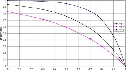
Fig. 4-6 shows the effectiveness during the phase change process at different dimensions and flow rates. Depending on these conditions some profiles are defined by a one dimensional solid/liquid front |

differentiating Eqn. (5) it is possible to determine the minimum effectiveness for a given set of parameters. Therefore:
SHAPE * MERGEFORMAT

and others by a 2 dimensional front. In the figures the effectiveness ranges from near unity and reduces to zero at the 100% phase change condition. The effectiveness at the 0% phase change proportion is the maximum effectiveness when the heat transfer area is maximum and the thermal resistance within the PCM is minimum. During the phase change process, the heat transfer area reduces and the thermal resistance within the PCM increases, reducing the NTU, and decreasing the effectiveness. The 100% phase change condition reflects a zero heat transfer area, and subsequently delivers a zero effectiveness.
|
Fig. 4. Impact of mass flow (kg/s) on the effectiveness with respect to the proportion which has changed phase. H=50 mm, phase change is 2 dimensional. Capacity is constant. |
 1
1
0.9 0.8 0
Fig. 4 show the effectiveness for different mass flow rates and heat transfer areas for a PCM slab of thickness 100 mm. Fig. 4 shows that at higher mass flow rates the effectiveness is reduced. Fig. 5
shows the impact of heat transfer area by increasing the length of the slab, and as expected, a higher heat transfer area increases the effectiveness. A slab thickness of 100 mm was chosen as it provided 2 dimensional heat flow. For slab thicknesses of less than 100 mm the condition defined by Eqn. (8) fails, and the heat flow is one dimensional. This suggests that for most applications of PCM slabs in air the one dimensional analysis is sufficient.
|
Fig. 5 increases the heat transfer area by increasing the length, which increases the capacity. Fig. 6 presents effectiveness curves for different slab thicknesses with the overall storage capacity unchanged. Therefore, a decreased slab thickness will result in a lower mass flow rate at each slab and a higher heat transfer area. As expected at lower slab thicknesses the effectiveness increases. In addition the effectiveness at these thicknesses is defined by one dimensional heat flow.
Portion of phase change (1 — S) |
Fig. 6. Impact of H (mm) on the effectiveness with respect to the proportion which has changed phase. At
H=50 mm, phase change is 2 dimensional, and at other H values it is one dimensional. Capacity is constant, total
mass flow = 0.35 kg/s.
For solar combisystems, water tank storage is the state-of-the-art choice [2]
However there are ways to improve the efficiency of water tank stores and the overall performance of a water based combisystems. Several topics deserve R&D attention to be improved: stratification devices, heat losses, system integration.
|
Fig. 2: In these detailed simulations from DTU, Denmark, the best performer in Zurich climate is clearly the double stratifier solution. |
|
When there is no stratifier (figure 4), the internal heat exchanger solution performs best. Fig. 3. Detailed simulation from DTU Denmark showed that model 2 showed slighlty better annual performance than the two others |
 |
Stratification devices allow better stratification of hot water in a tank so that less auxiliary will be needed to meet the peak load during DHW draw off for example. There are several solutions on the market but all are somehow complicated and expensive. Pervious fabrics have been investigated in Denmark and the best choice exhibits promising results compared to current devices. It is a two concentric layers system, where water can leave at any level depending on its temperature relative to Denmark investigated 3 configurations of combisystems whose only variation is the stratification scheme in the water tank (figure 2). The alternative with 2 stratification devices, one for the solar loop and one for the return loop perfoms best with a 20% improvement of the annual solar energy delivered to the load in the best case compared to the no stratification device case.
1.3. Theoretical model
A schematic description of the ICS is presented in figure 4. The model consists of a multilayer system containing a transparent glass cover, an air layer, an absorbent surface, an exchanger, a composite storage material, a polymer envelope and a thermal insulation.
x
Transparent Glass Cover (Tg) Air Layer
Absorber surface (Ta)
Heat transfert fluid (Tf)
Composite material (TJ
|
L |
|
nsulation |
Polymer Enveloppe (Tp)
Exterior (Tamb)
Z
Fig.4: Schematic representation of the ICS
We consider here a uniform temperature of both the glass cover and the absorber. Only the composite material and the polymer envelope are discretized along the x direction.
|
Cp,^=g[ — [.+p,)]+t~t—■.(Ta ‘ — T, ■)+e,* (r* ‘ — Tg ■)+… |
|
m |
|
(eq.4) |
Temperatures of the absorber surface and the transparent cover are determined using equation 4 and 7. For the transparent cover (Tg):
г г
a g
|
10.3 |
… + 1.05Ta — T, .(Ta — T,) + hamb/,(Tamb — T,)
These expressions take into account successively the absorption of solar energy by the cover, thermal radiative heat transfert between the absorber and the cover6 and also between the cover and the sky. The temperature Tsky is calculated through the empirical formula[7]:
|
(eq.5) |
![]() Ty = 0.0552X15,
Ty = 0.0552X15,
sky amb
Convective transfer coefficients between the glass and the absorber are calculated using equation 6[8].
ha/, = 1.05.|Т — Tg f 3 (eq.6)
Convective transfer with the environment are supposed to be constant and approximate to hc-amb=17 W. m"2.K_1 which is the value for a wind speed parallel to the solar collector of 3m. s_1.
|
(eq.7) |
|
C dTa G( ) maCPa~dT = G(T, aa ) + |
|
a |
|
1 + -1 — 1 |
|
^4 — Г,4) + 1.05Ta — Tg .(Ta — Tg ) + hQ /, .(TQ — Tc ) |
|
г |
|
г |
|
a |
|
g |
For the absorber (Ta)
Absorber temperature is function of the solar absorbance, radiative heat transfert between the absorber and the cover, convective exchange between absorber and glass cover. The thermal resistance of contact between the absorber and the composite is taken into account in a global transfer coefficient
ha/c.
Considering a global heat transfer coefficient between the polymer and the composite, the system of differential equation is given by:
For the composite:
|
(eq8) |
![]()
|
(eq.9) |
![]() pccpc дт — + V(-kc VTC) = 0 dt
pccpc дт — + V(-kc VTC) = 0 dt
For the polymer
P Рсрр~^ + V(-Ap VTp) = 0
|
— к |
|
c |
|
h /, (T — TP) |
|
(eq-10) |
These equations are linked through the heat exchange at the interface between the composite and the polymer:
|
— к |
|
( дТ Л |
|
(eq11) |
|
= hp / c (Tp — Tamt, ) |
The heat exchange at the exterior boundary of the polymer is calculated via equation 11.
Where hp/c is a global transfer coefficient regarding both transfer with the insulated material and the convection at the top back of the ICS.
In the model, the effective heat capacity Cpc of the PCM takes into account its latent heat (solidification/fusion) through the integration of an effective function (Cp=f(T)) defined by a preliminary calorimetric analysis of the material.
These are solved with the simulation package Comsol® which is based on the finite-element method. The geometry of the solar collector leads to a simple one-dimensional system during the charge. During discharge, the flowing fluid imposes to consider a two-dimension system.
Fig. 2 shows the share of the annual thermal energy requirement that can be met directly by the useful solar yield per house type. Thermal savings in the range of 9% to 22% could be achieved without thermal energy storage technologies. To achieve higher solar fractions, the use of TES technologies is required. Fig 5 shows the predicted storage capacities required per house type in
order to achieve 50% solar fraction for a range of collector areas. For this example the collector considered is the same for all house types and is south facing with 45o tilt.
The graphs show a generally very clear threshold of the collector area needed per house; absorber areas larger than this threshold would not contribute to much higher thermal savings or smaller TES sizes. Figure 5 also shows that in certain cases (e. g. house 12) very few m2 of collector would suffice to achieve the 50% solar fraction, while for others (e. g. house 3) more m2 than were available would be required in order to meet 50% of the total thermal energy needs with reasonable store sizes. The optimum balance between TES capacities and collector areas will be defined by the economics of the systems and the space limitations regarding collector mounting (available roofs, external walls and other external space) and TES volumes.
presents the percentage of the roofs’ area (or external walls’ area for models 5 &12) that remains unused for each house type. This figure reveals that if more collectors’ sizes become available in the future, then a larger solar thermal yield could be achieved. The overshadowing
analysis is conducted in Ecotect. The results reveal the portion of the total collectors’ area which remains non-shaded for every hour of the year and for each one of the roofs of each house type.
The I-beam solar radiation each of the roofs is then calculated in TRNSYS in Kj/hr*m2. The collectors’ yield is adjusted with the non-shade coefficient and with the efficiency of the collector which is taken as 0.7.
Figure 3 contains 12 graphs, one for each of the 12 houses modelled, showing the monthly thermal energy requirement in relation to the monthly collectors’ yield. All graphs show predictions using the tmy2 weather data. On two of the houses (with the highest and lowest demands) the predicted demands with the actual weather data of year 2007 are compared to those with the tmy2. Year 2007 was a significantly warmer year than average for Cardiff and therefore the predicted space heating demand is much lower than average and the solar thermal energy availability calculated with this data is much higher. This comparison reveals a much larger potential for solar thermal as average temperatures increase.

|
|
|
|
|