Как выбрать гостиницу для кошек
14 декабря, 2021
Сегодня каждый, кто собирается в отпуск и не знает, с кем оставить своего котика или кошку, может во[...]
Fig. 1 shows the typical arrangement for plates of PCM separated by a gap in which the heat transfer fluid passes. As the fluid flows along the plate heat is convected between the fluid and the PCM plate, and phase change occurs. This phase change occurs in both the x and y direction. An experimentally validated two dimensional model of a plate with PCM has been developed [5]. The model demonstrated that this phase change begins at the upstream top corner of the slab (Fig. 2). As this process continues the top layer of the plate changes phase first since it is in direct contact with the wall where the resistance is least. As the process continues, this solid/liquid line continues to progress down through the plate. Furthermore, this line has a slight incline, such that the thickness of the section which has changed phase is greater at the upstream end of the slab.
In addition to this process the plate is changing phase in the direction of the flow path. The largest driving force exists at the inlet, where the difference between the fluid temperature and phase change temperature is maximum. Due to this driving force, a solid/liquid front begins at the upstream face of the plate. Once phase change of an initial section of the plate has been complete, the temperature of
|
Fig. 2. Section of PCM slab showing solid/liquid front during phase change. (Courtesy of [5]) |
|
y |
![Подпись: Fig. 2. Section of PCM slab showing solid/liquid front during phase change. (Courtesy of [5])](/img/1128/image314.gif) |
|
the PCM within this section approaches the inlet fluid temperature reducing heat transfer. As a result, the maximum driving force occurs further downstream at the next section of the plate. Consequently a vertical solid/liquid line moves down the length of the plate during the phase change process. In essence, the PCM begins to change phase at the top upstream corner of the plate and ends at the centre of the downstream face of the plate (Fig.2). The assumed location of the solid/liquid front in both [2] and [3] is inconsistent with this result.
The thermal resistance is a function of the overall heat transfer coefficient between the fluid and PCM, and the heat transfer area. Fig. 2 shows that the solid/liquid line moves both the x and y direction, and therefore both the heat transfer area and the overall heat transfer coefficient change with time. Since the dominant direction of the front is along the x and y axis, it is proposed that this front can be approximated by a rectangular profile (Fig. 3). By assuming that the front is defined by a rectangular profile, the heat transfer can be treated as a one dimensional process and defined by a single thermal resistance. This thermal resistance can be characterised by an overall heat transfer coefficient and a heat transfer area, as defined by Eqn. (1), both of which change with time.
|
Fluid flow |
|
Heat transfer wall |
|
Fig. 3. Approximation of solid/liquid front during phase change. |
|
RT =• |
![]() 1
1
UA
|
(1) |
![]() U = 1 + У h k A = xW
U = 1 + У h k A = xW
The equation for the overall heat transfer coefficient ignores the axial heat conduction. As described in [2], given the low thermal conductivity of the PCM axial heat flow is negligible. As found in [5], natural convection is also ignored due to the small slab thicknesses used.
In practice a PCM storage system can be described as a heat exchanger in which the heat transfer fluid exchanges heat with the PCM at the phase change temperature. The performance of a heat exchanger is described by the heat exchange effectiveness. The effectiveness equates to the ratio of the actual heat transfer to maximum possible heat transfer, which is defined by the maximum temperature difference between the heat transfer fluids. A PCM storage system can also be characterised by its effectiveness, defined by Eqn. (2), [6]. Therefore maximum effectiveness of unity occurs when the heat transfer fluid exits at a temperature equal to the phase change temperature. Effectiveness is a useful parameter from a design perspective. In an application of a TSU with PCM, the outlet temperature during the discharging process must meet system specifications. Therefore, the minimum effectiveness can be found after which the TSU is ineffective.
|
£ it |
|
where NTU = |
|
UA m Cp |
|
(2) |
|
T — T X1 12 T — T 1 pcm |
|
= 1 — e |
|
-NTU |
 |
|||
The effectiveness relates the NTU between the fluid and the solid/liquid front. However unlike conventional heat exchangers the NTU changes with time as U and A change. At this front the specific heat of the PCM is infinite as phase change is occurring. Therefore, as expressed in [3], the effectiveness of a TSU with PCM, at time t, can be defined by the effectiveness equation for boilers or condensers [7]:
Eqn. (2) ignores the sensible storage component and therefore initially can begin at unity and at the end of the phase change process will reduce to zero. In heat exchanger analysis, the NTU is constant for a given mass flow rate. However, in a TSU for a constant mass flow rate the amount of phase change which has undergone affects the location of the solid/liquid line which defines U and A, changing the NTU with time. Rather than using time as a variable as conducted in [4], the proportion of material which has yet to change phase or phase change fraction can be used as the defining variable. The phase change fraction directly relates to the solid/liquid line within the PCM, therefore, time can be removed as a variable. The phase change fraction for a plate is defined by:
|
(3) |
![]() 5 =
5 =
LH
|
(4) |
|
1 H 5LH hxW kxW k(x )2W |
 |
||
Substituting Eqn. (3) into Eqn. (1), the total thermal resistance is defined as:
Therefore the heat exchange effectiveness can be written in terms of x:
-1__________
|
m Cp s = 1-e |

|
(5) |
![]() 1 H — 5LH і hxW kxW k(x )2W J
1 H — 5LH і hxW kxW k(x )2W J
Eqn. (5) defines the effectiveness at a given fluid flow rate and phase change fraction with respect to the distance x. In the absence of a model of the TSU this distance cannot be found. However by
|
ds dx |
|
■ = — e |
|
— NTU |
|
1 |
|
1 |
|
1 |
|
m c |
|
1 H 5LH — + |
|
2 |
|
H 2LH5 + |
|
hWx2 kWx2 kWx3 |
|
hWx kWx kWx2 |
|
Equating Eqn. (6) to zero, the minimum effectiveness can be found to occur at: LH25 |
|
x = |
|
— + H h |
|
(7) |
|
Therefore: |
|
-1 |
|
m Cp |
|
( Гк ^ 2 > [k+H к+hH + к+hH l. h |
|
2h2LHWS 2hkWLS 4kWLHS |
|
s min = 1- e |
|
(8) |
|
However Eqn. (8) is only valid if y < H, therefore from Eqn. (4), x > 5L. Resolving this inequality — gives H > — . If this condition is not met then the minimum effectiveness occurs at x = 5L, and: h |
|
hLWS s = 1-e mCp (9) This condition effectively states that the solid/liquid front is vertical and the heat transfer is one dimensional, as assumed in [2]. Furthermore, given that the thermal conductivity of the PCM is no longer a variable, the heat transfer area in Eqn. (9) is defined by the phase change fraction. Eqns. (8) and (9) provide a representation of the TSU in terms of two and one dimensional heat flow respectively, defining the minimum effectiveness for a given set of conditions and dimensions. In practice the effectiveness may be higher, however the equations define the effectiveness in terms of a single parameter, the phase change fraction. To investigate this representation of a TSU, an analysis will be conducted on a TSU with PCM for an air based space heating system. Charging involves melting the PCM and discharging encompasses the freezing of the PCM. The specifications include: 70 kWhrs storage, design room temperature of 21 oC. Properties of the PCM include: melting temperature of the PCM of 42oC, latent heat of 145 kJ/kg, thermal conductivity of the solid and liquid phase = 0.6 W/mK, gap thickness = 5 mm, L = 1 m and W = 1 m. The heat transfer coefficient is defined by fully developed flow with a Nu=3.66 for laminar flow at constant wall, and Eqn. (10) for turbulent flow with n=0.3 and 0.4 for the fluid being cooled or heated respectively [7]. Nu=0.023 Re08 Pr n (10) |
|
Fig. 4-6 shows the effectiveness during the phase change process at different dimensions and flow rates. Depending on these conditions some profiles are defined by a one dimensional solid/liquid front |
differentiating Eqn. (5) it is possible to determine the minimum effectiveness for a given set of parameters. Therefore:
SHAPE * MERGEFORMAT

and others by a 2 dimensional front. In the figures the effectiveness ranges from near unity and reduces to zero at the 100% phase change condition. The effectiveness at the 0% phase change proportion is the maximum effectiveness when the heat transfer area is maximum and the thermal resistance within the PCM is minimum. During the phase change process, the heat transfer area reduces and the thermal resistance within the PCM increases, reducing the NTU, and decreasing the effectiveness. The 100% phase change condition reflects a zero heat transfer area, and subsequently delivers a zero effectiveness.
|
Fig. 4. Impact of mass flow (kg/s) on the effectiveness with respect to the proportion which has changed phase. H=50 mm, phase change is 2 dimensional. Capacity is constant. |
 1
1
0.9 0.8 0
Fig. 4 show the effectiveness for different mass flow rates and heat transfer areas for a PCM slab of thickness 100 mm. Fig. 4 shows that at higher mass flow rates the effectiveness is reduced. Fig. 5
shows the impact of heat transfer area by increasing the length of the slab, and as expected, a higher heat transfer area increases the effectiveness. A slab thickness of 100 mm was chosen as it provided 2 dimensional heat flow. For slab thicknesses of less than 100 mm the condition defined by Eqn. (8) fails, and the heat flow is one dimensional. This suggests that for most applications of PCM slabs in air the one dimensional analysis is sufficient.
|
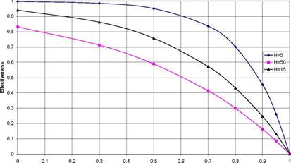
Fig. 5 increases the heat transfer area by increasing the length, which increases the capacity. Fig. 6 presents effectiveness curves for different slab thicknesses with the overall storage capacity unchanged. Therefore, a decreased slab thickness will result in a lower mass flow rate at each slab and a higher heat transfer area. As expected at lower slab thicknesses the effectiveness increases. In addition the effectiveness at these thicknesses is defined by one dimensional heat flow.
Portion of phase change (1 — S) |
Fig. 6. Impact of H (mm) on the effectiveness with respect to the proportion which has changed phase. At
H=50 mm, phase change is 2 dimensional, and at other H values it is one dimensional. Capacity is constant, total
mass flow = 0.35 kg/s.