Как выбрать гостиницу для кошек
14 декабря, 2021
Сегодня каждый, кто собирается в отпуск и не знает, с кем оставить своего котика или кошку, может во[...]
1.1. ICS PCM conception
The system consists of an expanded natural graphite (ENG)/paraffin composite plate placed behind a solar absorber (figure 1).
|
(eq.1) |
|
T + T |
|
П = П — a1 К — a2G(T, J)2 with К = — |
|
2 |
|
o_ T |
|
G |
The absorber is made of aluminium sheet co-laminated. This absorber integrates channel pattern to allow thermal exchange with a heat transfer fluid. The aluminium sheet has been recovered with a solar black paint (a=96.2%, s=86%). The efficiency of the solar absorber is defined as[4] :
Experiments following prEN12975-2 European standard have been achieved and the optical efficiency of the absorber found is n0=0.88. The heat loss coefficient ai is equal to 8.87 W. m-2.K-1 and the coefficient a2 is very small and so neglected.
|
Fig. 1. Schematic presentation of the ICS-CENG/PCM system. |
 |
The ENG plate of the storage media was provided by SGL Company and filled with Rubitherm RT65 paraffin. This plate was fixed with a copolymer envelope, confining the molten PCM. The whole system was placed in a conventional flat plate collector frame with a glass cover transparent to visible light and mineral wool insulation.
1.2. Experimental set up
The solar collector is placed on a support adjustable in both azimuth and solar height. A pyranometer (kipp and zonen) measures the whole incident solar irradiation at the surface of the collector and a panel of thermocouples is placed within the composite and on the absorber. The heat transfer fluid flow is assured by a pump and regulated by a manual valve.
To characterize the storage collecting system we carried out series of measurements which consisted of:
• Following the temperature change in the composite, at the surface of the ICS and the polymer, during the charge phase. At this stage, the heating fluid is not flowing inside the absorber. The ICS is oriented in order to collect a maximum of solar energy.
• Following the temperature difference between the inlet and outlet of the absorber during the discharge processes, when solar collector is turn back from the sun. This discharge of the stored energy is assured by a controlled mass flow fluid circulation with constant inlet temperature.
2.3. Predicted Thermal Energy Requirements
Table 4 shows the predicted annual thermal requirements for space heating and space cooling (a
COP of 0.6 for the chiller thermal to thermal efficiency was used for the absorption chiller) for each house and the thermal energy required for domestic hot water needs as taken from Annex 42. The weather data used in the calculations is the TMY2 type and the calculations were conducted in TRNSYS.
|
Table 4. Thermal energy requirement for space heating, cooling and domestic hot water preparation.
|
The main findings of the studies on closed adsorption storage, as reported by AEE INTEC in Austria, are the following:
• A sorption heat store with the material pair silica gel and water was developed, the system was scaled up for use in a single-family house and a first pilot plant was built.
• In this project, it could be shown for the first time that sorption technology for heat storage is technically feasible in a live test. The system concept, as well as the control strategy, have been proven to be functional under real operating conditions.
• The operation of the system was satisfactory and the system concept could be implemented in further systems. It has been shown that sorption storage with the used material combination is technically feasible. However, the temperature lift that can be achieved is only technically useful in a relatively small range of water contents. As long as the silica gel is very dry, the temperature lift
is sufficient. But starting at a water content of approximately 13%, the temperature lift is not large enough to compensate for higher losses in heat exchangers, pipes and tanks. That means that the energy density of the material that can be used in a real application is much smaller than both the theoretical one and what has been measured under laboratory conditions. Therefore, a large quantity of material would be necessary which makes sense neither technically nor economically.
• The used material has been chosen because it is manufactured in mass production and therefore inexpensive. Up to now, there are very few research institutes that develop sorption material specifically for heat storage. In most cases, the focus is on heat pumps, cooling machines or gas separation and drying processes. Singular projects have shown that the development of sorption materials for heat storage is technically feasible. So far, these materials have been expensive or for example corrosive.
• A TRNSYS model for the sorption store including the evaporator/condenser heat exchanger has been developed and a TRNSYS deck has been set up for the Task 32 reference conditions.
• For the simulations reported in report B6, a different sorption material has been used to show the possibilities of the store/system concept. The system concept was similar to the one used in the field test system which was using the sorption store only for space heating and not for domestic hot water preparation. This was done because of the low temperature lift of the material pair silica gel / water. The temperature lift of the material chosen for the simulations is much higher. Therefore, domestic hot water preparation would be feasible. But in the simulations, the solar fraction was limited to a value below 100% even for very large storage volumes because of the mentioned system design.
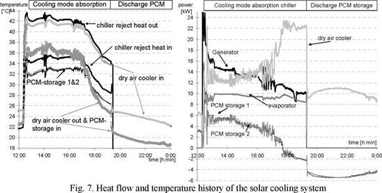
After the standalone tests on the storage were completed, the storage was integrated into the new system for solar heating and cooling at the ZAE Bayern. Starting in fall 2007, the performance of the system was monitored during operation [2, 3].
To test the system design-point performance (Fig. 7), between 12:00 and 16:00 the outlet temperature of the dry air cooler was fixed to 36 °C by adjusting its ventilator frequency.
|
|
After the warm up of the absorption chiller, the system provides about 10 kW chilled water using 14 kW of driving heat at about 90 / 80 °C, as designed. 50 % of the reject heat is delivered by the dry air cooler at 41 / 36.5 °C and the latent heat storage at 36.5 / 32.5 °C in each case. In the evening, the return temperature from the dry air cooler is sufficient for discharging the latent heat storage and cooling the absorption chiller simultaneously. The latent heat storage is then completely discharged during night time.
J. Candanedo1* and A. K. Athienitis[6]
1 Solar Laboratory, Department of Building, Civil and Environmental Engineering, Concordia University
* Corresponding Author, j candan@encs. concordia. ca
Abstract
This paper presents the results of simulations used in the design of predictive control strategies for the Alstonvale Net Zero Energy House (ANZEH), an advanced demonstration solar house to be built near Montreal, Canada. A description of the ANZEH is presented. Predictive control was used for managing the interaction of the energy resources with passive and active thermal storage. This action has significant impact on the overall energy consumption, peak demand and comfort. It has been found that, in this house, a properly designed control strategy can achieve free space heating over two consecutive cloudy days, if preceded by three sunny days, relying solely on the solar resource.
Keywords: active storage, passive storage, net-zero energy house, passive solar house
1. Introduction
|
Figure 1. Alstonvale Net Zero House: south facade (left) and street view (right) (Images courtesy of Sevag Pogharian) |
 |
The Alstonvale Net Zero Energy House (ANZEH) is one of the winners of the EQuilibrium Initiative, a design competition organized by the Canada Mortgage and Housing Corporation (CMHC) between 2006 and 2007 [1]. This house is currently under construction in the town of Hudson, in the metropolitan region of Montreal. Numerical models were used to study the response of the house under several control strategies. A description of this house, as well as the results of these simulations, is presented here.
energy needs. It has been designed with advanced (low-e, triple-glazed, argon-filled) south-facing windows (50 m2 in total), occupying 43% of the south facade. There are also windows on the east and west walls, while there are no windows on the north facade. In order to increase its thermal mass, and therefore its capacity for passive thermal storage, the house was designed with 15-cm thick concrete slab floors and a large interior masonry wall. The ANZEH has a solar chimney connected to the indoor space. This chimney has an east-facing controllable damper, which remains closed during the winter; during the summer, it enhances natural convection currents, thus removing hot air from the house interior. Other features include the use of energy-efficient appliances and a design that enhances daylighting complemented with low consumption compact fluorescent lamps. Properly-sized overhangs prevent excessive solar heat gains during the summer. Motorised theatre curtains, located behind the main south-facing windows, contribute to controlling solar heat gains, while improving comfort and adding to the aesthetic value.
Hudson is located 50 km northwest of Montreal (45°26’ N and 74°10’ W). Montreal weather data was used in the design of the house; the winter design temperature is -23 °C [2].
P. Widmer
Jenni Energietechnik AG, Lochbachstrasse 22, CH-3414 Oberburg (Switzerland),
patrick. widmer@jenni. ch, www. jenni. ch
Abstract
Europe’s first apartment block to be heated entirely by solar energy was completed 2007 in Oberburg, Switzerland.
Keywords: Solar energy, Solar tank, Apartment building, Solar collectors
|
Fig. 1. Front side of the apartment block |
 The heat for the eight apartments in the building is provided by 276 square metres of solar roof collectors which are connected to a water storage tank with 205’000 l capacity. The tenants will never have to pay any heating bills because there is no additional heating energy required.
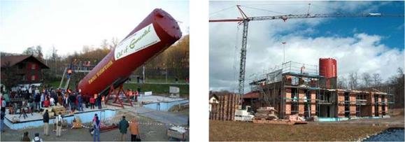 |
The water tank, which stands upright in the middle of the building, has sufficient reserves to ensure enough water can be warmed to heat the building and provide hot water year round even with below average sunshine. The building meets the highest energy standards in Switzerland.
|
EUROSUN 2008 1st International Congress on Heating, Cooling, and Buildings — 7th to 10th October, Lisbon — Portugal / |
|
Fig. 4. Installing the 276 m2 solar thermal collectors |
 |
Fig. 5. Finished building
A. Lazaro*, J. M. Marin, P. Dolado, B. Zalba
Instituto de Investigation en Ingenieria de Aragon. I3A
Grupo de Ingenieria Termica y Sistemas Energeticos. GITSE
Dpto. Ingenieria Mecanica. Area de Maquinas y Motores Termicos.
Universidad de Zaragoza. Campus Politecnico Rio Ebro.
Edificio “Agustin de Betancourt”, Maria de Luna s/n. 50018 Zaragoza
Phone: 976762566, Fax: 976762616
Corresponding Author, ana. lazaro@unizar. es
Abstract
Building applications of phase change materials (PCM) and its contribution to energy efficiency are being studied. One of the most promising applications of thermal energy storage with phase change is the inclusion of microencapsulated phase change materials into building materials. It could be for external enclosure (increasing thermal inertia) or other applications inside the building (walls or furniture). Objectives and effects are different in each case, and it should be tested in order to corroborate that the effect is as were designed. Some new products are being introduced into the market. Thermal studies are needed to test them and to design properly its applications.
At University of Zaragoza (Spain), an experimental setup based on energy balances used to measure stored energy in macroencapsulation of PCM was modified to measure thermal effect of phase change materials inclusion into different elements.
Those tests are based on transitory heat conduction analysis on samples. A new methodology of test combining heat capacity measurements and thermal effect tests and data analysis was developed to study thermal effect as a comparison between the same element with and without PCM. Some results are also presented in this conference [13].
Keywords: Phase Change Material, Thermal Energy Storage, Experimental, Buildings
Thermal Energy Storage using phase change materials is being studied for building applications [1]. Some authors proposed the use of macroencapsulation of PCM in wallboards [2-4] or in Panel sandwich [5,6] to increase thermal inertia. Bentz et al. [7] proposed three different applications of PCM in concrete at different temperatures and Medina et al. [8] proposed the use of structural panels in combination to macroencapsulation of PCM. Recent years, microencapsulation of PCM has been proposed to solve problems of leakages and distribution in those kinds of applications. Schossig et al.
[9] and Cabeza et al. [10] have studied the addition of microencapsulated PCM in building materials to reduced energy consumption in buildings.
Depending on the application, the climate and the season, the effect of PCM in buildings could be satisfactory or not [11]. It is need to study thermal properties of PCM itself, to know the temperature range within the phase change takes place, enthalpy as a function of temperature to know the energy storage capability and thermal conductivity to study the heat transfer resistance. It is noteworthy that heat capacity and density could be estimated from proportional mass rules, but thermal conductivity depends on molecular contact between the components of the material and has to be studied together.
Thermal effects of PCM in building materials are two: it modifies the energy storage capability and the heat conduction coefficient. Therefore, thermal diffusivity of the sample becomes necessary to study transient heat conduction of the wall and to evaluate thermal effect of PCM addition in building materials. For example, regarding to external enclosure, thermal behaviour depends on global heat transfer coefficient (U) and thermal inertia, which provides deferment and diminish the amplitude of the heat-flow wave. The objective should be in this case to decrease thermal diffusivity.
There are not many commercial devices to study thermal diffusivity as a function of temperature. They use small samples and from some buildings materials is not possible to have a representative samples (for example concrete with PCM). The aim of the work at University of Zaragoza is to be able to evaluate two effects, thermal conductivity and energy storage capability as a function of temperature of building materials.
M. Belusko* and F. Bruno
Institute for Sustainable Systems and Technologies, University of South Australia, Australia
Corresponding Author, martin. belusko@unisa. edu. au
Abstract
Representations of thermal storage systems with phase change materials are predominantly developed through numerical modelling. However, as design tools, these models are of limited application. A number of representations are investigated which attempt to characterise thermal storage systems using the effectiveness-NTU technique. From these studies together with observed results from numerical modelling, a generic representation is presented for phase change materials in flat containers. This representation leads to the development of a generic characterisation of the effectiveness of a thermal storage system with respect to a single parameter. This characterisation can readily be used as a design tool for sizing and optimising a thermal storage unit with flat containers of phase change materials.
Keywords: thermal storage, phase change materials, effectiveness
Numerous mathematical models of phase change material (PCM) in the flat plate arrangement in thermal storage units (TSU) have been developed over the years. These models are numerical models of encapsulated PCM subjected to convection [1]. These models have been used to determine the performance of the TSU for design and simulation purposes. However little attention has been placed on using these models to develop generic representations which can be readily used for the characterisation and ultimately the design and optimisation of a TSU with PCM.
TSU with plates of PCM for solar heating has been examined [2]. Finite difference models were developed which determined the number of transfer units (NTU) between the heat transfer fluid and PCM. The models tested a number of assumptions but always assumed that phase change occurred in one dimension, along the flow path. It was found that assuming an infinite NTU adequately described the TSU within a solar heating application. This NTU was a function of the convection heat transfer coefficient and heat transfer area of the wall. The NTU was assumed constant throughout the phase change process and only referred to the fluid side. However, during the phase change process, within a PCM container the heat transfer occurs between the fluid and the PCM at the liquid/solid front which changes with time. By assuming that the phase change process occurs in the direction of flow, it can be argued that the heat transfer area is reducing, decreasing the NTU.
An entropy optimisation representation for PCM tubes which also determined the NTU between the fluid and PCM at the liquid/solid front has also been developed [3]. This model accounted for the additional thermal resistance within the PCM during the phase change process, resulting in a
decreasing NTU during the phase change process. However this representation assumes the phase change process occurs uniformly with the solid/liquid front perpendicular to the direction of flow, opposite to that in [2]. Consequently, this method also assumes the heat transfer area is constant during the phase change process. Both approaches are potentially overestimating the NTU, however have demonstrated that the NTU is a useful parameter to evaluate the heat transfer in the process. A two dimensional model for PCM in tubes within a tank is described in [4]. The NTU was solved numerically and changed with time. Therefore the model effectively considered the heat flow between the solid/liquid front and the fluid. Consequently, the development of a simplified representation of the PCM is therefore dependant on being able to determine the NTU between the heat transfer fluid and the PCM at the phase change profile.
The representation developed in [3] enables the optimisation of the design of a TSU with PCM considering the exergy losses in the charging and discharging processes. It was shown that along with energy lost due to frictional losses, due to the 2nd Law of thermodynamics some of the energy stored is not released as it cannot meet the temperature requirements of the heat sink. However this technique does not readily lend itself to be used in an engineering design method where the objective is to meet a performance specification. The representation shown in [4] presents are more useful option, in which the TSU is characterised in terms of a heat exchange effectiveness and the NTU and effectiveness are a function of a dimensional time parameter. This approach will be expanded into a generalised representation of the TSU with PCM in plates, applying the s-NTU method, which does not involve numerical modelling.
The most efficient way to collect solar energy for space heating purposes is to do it at low to medium temperature, between 20 and 80C. Storage in this range is done since centuries with water.
Water is a good heat storage medium. One m3 of water can store 70 kWh between 20 and 80 C, that is the production of about 20 m2 of good flat plate solar collectors during a bright sunny day.
Keeping this energy in a water tank for a few days can easily be achieved by insulating the container with classical insulation material 10 to 12 cm thick.
The sensible heat capacity (ability to store heat in a sensible form) of water is one of the highest. On top of this interesting physical property, water has four other very important advantages over other material: It is non toxic, it is ubiquous, it is cheap, it is a fluid.
/
To store cold energy, say around 0C, water is also a very good storage material! Using its latent heat from liquid to solid (ice), water can store 91.6 kWh par m3 ! This, combines with the total reversibility of the process, makes clearly water the first choice when cold storage is needed for cooling purposes in building.
1.
|
How to store: 1’850 kWh = 6.7 GJ + Heat losses 25% Total capacity: 10 GJ Over 70 C temp. Diff. |
|
C |
|
S |
|
P |
|
W |
|
Energy density In MJ/m3 |
|
10 000 |
|
1 000 |
|
100 |
|
Figure 1 shows four ranges of solutions to store heat. Water over 70C, phase change materials (PCM), reactions based on sorption principle, and chemical reactions. |
|
10 20 40 60 80 100 200 400 800 1000 Temperature in C Fig. 1. Energy density vs temperature (log scale) and comparison of theoretical volume needed to store 10 GJ of heat based on four different principles [1]. |
The density that can be theoretically achieved is shown on the vertical axis where as the horizontal axis shows the temperature needed.
Water our best in class of today is still a low dense material compared to the other solutions and noticeably chemical reactions, where the storage volume for a seasonal store in a low energy house could be not bigger than 1 m3 compared to the 34 m3 of water we need today.
The IEA Solar Heating and Cooling Programme decided to investigate these 4 alternatives during 2003 to 2007 within Task 32 “Advanced storage concepts for solar and low energy buildings”.
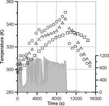 |
In figure 2, we present the temperature distribution in the ICS and the solar irradiation over the time.
|
Fig. 2. Solar irradiation ( |
 ) and temperature distribution at the interface absorber/polymer (o), at the interface PCM/polymer (A) and on the polymer (□)
|
MUE = — |
|
cCPc/,- Tin)+mcAHc + mcCPc/1(Te — Tf )+ mpCpp(T — Tin) |
|
A |
|
I G(t)dt |
|
(eq.2) |
The maximum useful efficiency (MUE) was first defined by Faiman[5], as the ratio of the maximum extractable energy to the total solar incident energy upon the collector during the heating period. This definition has been extended to ICS-PCM by Tey et al[1], and can be written in our case as (eq 2):
In this equation, the numerator (or EICS) represents the amount of energy stored by the composite and the polymer. This expression takes into account the sensible heat of the PCM in solid and liquid form, the latent heat of the PCM and the sensible heat of the polymer envelope.
According to the raw data illustrated in figure 2, the MUE was found to be 0.26. Considering that the efficiency of the absorber, defined by equation 1, at the working temperature of 320-350 K is approximately between 0.3 and 0.4, the relative amount of energy transmitted from the absorber to the composite and the polymer envelope ranges from 0.67 to 0.89. This means that between 67 to 89% of the solar energy captured by the absorber is charged in the storage media.
During the discharge phase, the energy extracted from the storage media by the fluid flow is:
‘% • (eq 3)
Ef = |m. Cpf.(To — Tt)
The ratio between Ec and Ef describes the efficiency of the ICS to release the store energy, ^discharge — In our case ndischarge is equal to 0.98.
|
1200- |
|
Q- 13 (Л a3 £ о CL |
|
0 |
|
|
800 |
|
2000 |
|
•1600 Q_ Q- 13 (f) •1200 D) <i3 c Ш |
|
800 |
|
10000 11000 12000 13000 14000 15000 Time (s) |
|
2400 |
|
400 |
 |
Figure 3 presents the power and energy released to the fluid over time. After 2000s, the composite has released 71% of the solar energy initially stored in more than 10,000s. This result illustrates the high potential of the composites materials to deliver the stored energy at a high power level.
Fig. 3: Power (o) and energy (A) released to the fluid over the time