Как выбрать гостиницу для кошек
14 декабря, 2021
Сегодня каждый, кто собирается в отпуск и не знает, с кем оставить своего котика или кошку, может во[...]
1.1. ICS PCM conception
The system consists of an expanded natural graphite (ENG)/paraffin composite plate placed behind a solar absorber (figure 1).
|
(eq.1) |
|
T + T |
|
П = П — a1 К — a2G(T, J)2 with К = — |
|
2 |
|
o_ T |
|
G |
The absorber is made of aluminium sheet co-laminated. This absorber integrates channel pattern to allow thermal exchange with a heat transfer fluid. The aluminium sheet has been recovered with a solar black paint (a=96.2%, s=86%). The efficiency of the solar absorber is defined as[4] :
Experiments following prEN12975-2 European standard have been achieved and the optical efficiency of the absorber found is n0=0.88. The heat loss coefficient ai is equal to 8.87 W. m-2.K-1 and the coefficient a2 is very small and so neglected.
|
Fig. 1. Schematic presentation of the ICS-CENG/PCM system. |
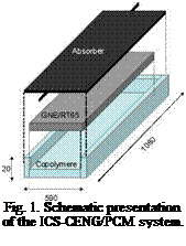 |
The ENG plate of the storage media was provided by SGL Company and filled with Rubitherm RT65 paraffin. This plate was fixed with a copolymer envelope, confining the molten PCM. The whole system was placed in a conventional flat plate collector frame with a glass cover transparent to visible light and mineral wool insulation.
1.2. Experimental set up
The solar collector is placed on a support adjustable in both azimuth and solar height. A pyranometer (kipp and zonen) measures the whole incident solar irradiation at the surface of the collector and a panel of thermocouples is placed within the composite and on the absorber. The heat transfer fluid flow is assured by a pump and regulated by a manual valve.
To characterize the storage collecting system we carried out series of measurements which consisted of:
• Following the temperature change in the composite, at the surface of the ICS and the polymer, during the charge phase. At this stage, the heating fluid is not flowing inside the absorber. The ICS is oriented in order to collect a maximum of solar energy.
• Following the temperature difference between the inlet and outlet of the absorber during the discharge processes, when solar collector is turn back from the sun. This discharge of the stored energy is assured by a controlled mass flow fluid circulation with constant inlet temperature.