Как выбрать гостиницу для кошек
14 декабря, 2021
Сегодня каждый, кто собирается в отпуск и не знает, с кем оставить своего котика или кошку, может во[...]
The control strategies presented here have assumed perfect knowledge of future conditions. It is desirable to incorporate modelling of “imperfect” forecasts for these events, and statistical uncertainty as an element in the decision. A statistical analysis of historical weather data could be used to study the probability of having a series of cloudy days, and could therefore be used as a decision-making tool in sizing a TES reservoir and the backup system. For example, this could help to decide what tank size is large enough to provide heat over 3 days, one week, etc., and the likelihood of that event. Other important aspects to take into account in the development of predictive control strategies are load management and the use of several operative temperatures throughout the day. On account of the different time scales involved, effective local loop control should also be emphasized to achieve the goals established by the supervisory control strategy. So far, a full house simulation has been used, but a simplified model (based on transfer functions) [9] could be implemented in order to apply techniques such as model predictive control (MPC).
Finally, simulations using several zones are needed to properly evaluate thermal comfort and its relation to handling passive thermal storage. Although these strategies have been applied to a particular solar house, the idea of balancing active and passive storage has general validity.
Financial support of this work was provided by the Natural Sciences and Engineering Research Council (NSERC) of Canada through the Solar Buildings Research Network (SBRN). Other SBRN partners include: Natural Resources Canada, which funded the BIPV/T system through the TEAM (Technology Early Action Measures) program; CMHC, which conducted the EQuilibrium demonstration program; and Hydro Quebec, which participates in the monitoring of the house. We would like to thank Quebec’s Agence de l’Efficacite Energetique for their valuable contribution to this project. We would like to thank Sevag Pogharian, developer of the ANZEH project. The first author would like to thank the financial support of NSERC through a CGS D2 Alexander Graham Bell Graduate Scholarship. We would like to express our gratitude to Andre Fry (Concept-R), Jocelyn Harel (Regulvar) and Claude Agouri (Air Techni) for their contribution of ideas.
[1] J. Candanedo, S. Pogharian, A. K. Athienitis, A. Fry (2007), Design and Simulation of a Net Zero Energy Healthy Home in Montreal, Proceedings of the Joint 2nd Solar Buildings Research Network (SBRN)-32nd Solar Energy Society of Canada, Inc. (SESCI).
[2] F. C. McQuiston, J. D. Parker, J. D. Spitler (2005), Heating, Ventilating and Air Conditioning, (5th ed.), John Wiley & Sons, Hoboken, New Jersey.
[3] J. Candanedo, A. K. Athienitis (2008), Simulation of the Performance of a BIPV/T system Couple to a Heat Pump in a Residential Heating Application, Proceedings of the 9th International Heat Pump Conference, Zurich, Switzerland.
[4] MATLAB Tech. Documentation, http://www. mathworks. com/access/helpdesk/help/techdoc/matlab. html
[5] J. Duffie, W. Beckman (2006), Solar Engineering of Thermal Processes (3rd ed.), John Wiley & Sons, Hoboken, New Jersey.
[6] R. Perez, P. Ineichen, R. Seals, J. Michalsky, R. Stewart (1990), Solar Energy 44 (5): 271-289.
[7] ASHRAE (2005), Handbook of Fundamentals, Atlanta, Georgia.
[8] TMY2 Data, http://sel. me. wisc. edu/trnsys/weather/tmy2data. htm.
[9] A. K. Athienitis, M. Stylianou, J. Shou (1990), ASHRAE Transactions 96(2): 839-848.
The computational domain includes the fluid inside the tank and the metallic wall. For the energy equation, it has been set that heat transfer to the ambient is dominated by convection, by imposing an a cosntant temperature at the sidewall while the top and the bottom have been considered adiabatic. At the symmetry line (r=0,z), gradient of temperature in radial direction has been assumed null. For the momentum equations, non-slip conditions at every solid wall, have been imposed. At the symmetry line, radial velocity has been set to zero, while the gradient of axial velocity component in radial direction has also been assumed null.
1.2. Discretization method
The numerical solution has been obtained by discretization, in finite volumes method and with fully implicit temporal differentiation, using cylindrical staggered grids as described by Patankar
[9] . Diffusive terms have been evaluated using a second order central differences scheme, while convective terms have been approximated by means of a SMART [10] scheme using a deferred correction approach. Pressure-velocity coupling was obtained by SIMPLEC method [11]. The resulting algebraic system of linear equations have been solved using the TDMA [9]. The criteria to stop transient simulation has been set as a function of the non-dimensional mean fluid temperature. As an infinite time is needed to fully cool down the fluid in the cylinder (that is, to reach exactly вл(т) = -1), it is necessary to terminate the numerical simulations at some point. In
this study, the criteria to stop the transient simulation has been taken as a general rule, all numerical simulationsn will be terminated when t = Tf, that is when QJj) = -0.99, the iterative
procedure has been truncated once the non-dimensional variables increments and residuals are lower than 10-5.
Because of the large variation near to the interface solid-liquid, it was necessary to use a mesh concentrates points in the boundary layer and is relatively coarse in the interior [12].
|
* |
 |
 |
Fig. 1. Schematic of the physical system and the computational domain.
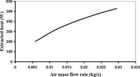
This research is conducted with conditions as follows. The numbers of thermosyphon is 10, 20. 100 tube and the length of condenser section 80 cm and evaporator section 20 cm. The average
temperature of LCZ 80 °C and temperature of inlet air at condenser section are 20 °C. The simulation time is 3 hours.
 600 500
%
400
о
.s
300
о
s
200
Ы
100 0
0 20 40 60 80 100 120
Number of tube
Fig.5.The relation between heat extraction and numbers of thermosyphon
Figure 8 is the result of heat extraction from the solar pond which is simulating at Khon Kaen province. As there are 100 tube thermosyphon, 22.22 mm. of outside diameter, the extracted heat is 560 W and the average temperature of the pond decreases from 80 to 78°C.
|
Tube dimeter(mm) Fig.6.The relation between the heat extraction from the solar pond and outside diameter of thermosyphon |
 |
According to the solar pond performance, the more the numbers of thermosyphon, more heat can be extracted with non-linearity. Because of when the number of thermosyphon increase, the thermal resistances, Zi and Z9, decrease. It is observed that the internal thermal resistance of thermosyphon has changed slightly due to the small temperature change that results the more heat can be extracted from solar pond because of the increasing in the numbers of thermosyphon.
|
0 1 •e § и a °w "o i/5 |
|
85 80 75 70 65 60 |
|
0 5 10 15 20 25 30 35 40 |
|
Tube dimeter(mm) |
|
Fig.7.The relation between average solar pond temperature and thermosyphon diameter |
 |
Regarding to the simulation, there are 3 outside diameters of thermosyphon; 12.70, 22.22, 34.92 mm. From the figure 8, the outside diameters of thermosyphon are 12.70 and 34.92 mm. the heat extraction are 1,088 W and 351 W respectively. The average temperature of the pond decrease from 80 to 78 °C as shown in figure. 7.
When the diameter increases, more heat extraction will be gained. Even though the size is increased, the rate of change of heat has decreased because of the internal thermal resistance also decrease. However, from figure.10, the extracted heat from solar pond is relatively small compared with the increasing of thermosyphon diameter Therefore, in the economic aspect; it is not worth to increase the thermosyphon diameter just to gain smaller extracted heat. Thus, this model is able to determine the appropriate diameter of thermosyphon for solar pond heat extraction.
|
Fig.8.The relation between the heat extraction from the solar pond and mass flow rate heat pipe heat Exchanger |
The effect of mass flow rate on heat transfer characteristics of a thermosyphon heat exchanger under normal operating conditions was investigated theoretically. The air face velocity ranged from 1 to 5 m/s and 70 tube thermosyphon the heat extraction are 202 W and 1,067 W respectively. As shown in figure.8
3. CONCLUSION
This research shows the simulation of heat extraction from solar pond at Khon Kaen Province in northeastern Thailand. The results show the capability of thermosyphon and indicate the optimum sizing of thermosyphon in solar pond application. Finally the simulation shows the theoretical possibility to use thermosyphon as the heat exchanger device to extract heat from solar pond.
Acknowledgements — This research was conducted under Rajamangala University of Technology Isan Khon Kaen Campus, Thailand. The authors would like to express their sincere appreciation for all of the support provided.
References
A. Akbarzadeh and G. Ahmadi (1980) Computer simulation of the performance of a solar pond in Southern part Iran, Solar Energy, Vol. 44, pp. 143-151
2. Huseyin Kurt, ethi Halici and A. Korhan Binark (1999) Solar pond conception — experimental and theoretical studies Energy Conversion & Management 41 (2000) pp.9393. Hillel Rubin, and Barry A. Benedict (1983) Modeling the Performance of aSolar Pond as a Sourace of Thermal Energy Solar Energy Vol 32 No 6 pp. 771-778
4. J. RHull (1980), Computer simulation of solar pond thermal behaviour, Solar Energy, Vol. 25, pp. 33.
5. J. Andrewe and A. Akbarzadeh (2004) Enhancing the thermal efficency of solar ponds by extracting heat fram the gradient layer Solar Energy, 78 (2005) pp.704-716
As a result of Subtask A of the FC+COGEN-SIM project [11], standard European and Canadian non-HVAC Electric Load and domestic hot water profiles have become available. The European non-HVAC Electric Energy Consumption Profiles of this study which have been suggested as “a good first estimate of domestic electrical energy consumption profiles for many European countries” are based on the UK domestic profiles monitored by EETS Ltd and the Welsh School of Architecture [12]. Using this data to simulate the internal gains due to appliances and lighting for the Welsh housing stock can therefore be considered the most accurate and realistic approach available for this purpose. For the domestic hot water consumption the Annex 42 report refers to two studies which suggest 116 litres per household per day as an average daily DHW consumption, based on a 45°C rise, for the UK. Therefore the energy required for the daily draw off of DHW for these models is assumed to be 6.07 kWh.
The main findings of the studies on the TCA technology [7], as reported by SERC, are the following:
• In comparison to storage in water, cold storage is more interesting that heat storage, as the available temperature range for water is much lower for cold than for heat. For the commercial machine the storage density for the store (that is also a heat pump) is roughly 5 times greater than that for water for cold whereas it is only 1.5 times greater for heat [4].
• The thermal storage of the TCA is sufficient for small scale solar cooling applications that do not have large night cooling loads. Otherwise additional storage is required. [8].
• The temperature lift for the prototype and commercial heat pump/stores is relatively low and limits the application range to systems with low temperature differences between cold/heat distribution system and the desired temperature of the conditioned space [8].
• LiCl, the salt used in all stores so far, is not suitable for seasonal storage due to its high cost (~3600 €/m3) [4]. However, the storage density would be approximately 2.7 times that of water for seasonal storage of 1000 kWh.
• A TRNSYS model of process and the controller for commercial machine have been developed
[9] and are available from the authors.
• The problems with unwanted crystallisation and non-condensable gases in the storage have been solved and the store has been redesigned for rational production resulting in a reliable process. The technology has been commercialised under the product name ClimateWell 10. The heat pump/store is sold mainly for solar heating and cooling applications in Mediterranean countries.
To allow the use of a single storage in the heating mode as well as in the cooling mode to reject waste heat, the heat has to be stored in a very narrow temperature range around 30 °C. This makes the use of a latent heat storage with a PCM melting around 30 °C most promising. The development and tests on several functional models of the latent heat storage are described in [1]. After completion of test on functional models, a full scale storage consisting of two storage modules was built in fall 2006. This paper reports on the stand alone tests on the full scale storage, and the tests performed after the storage was integrated into the system during summer operation in 2007 and winter operation 2007/2008.
1.1. Construction of the storage
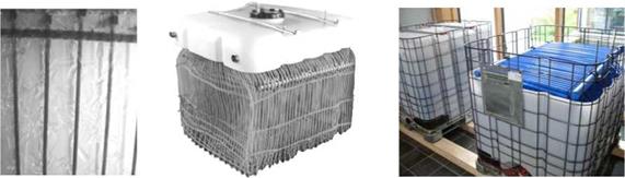
|
The full scale storage, shown in fig. 3, consists of two modules. Together, both modules have a total volume of 1.5 m3. They contain together about 2 t of CaCl26H2O as PCM. The melting point of CaCl26H2O is about 29 °C. The total design storage capacity is 120 kWh in the temperature range from 25 °C to 33 °C.
Fig. 3. Capillary tubes surrounded by crystallized PCM (left), heat exchanger with capillary tubes (center), and the two storage modules (right). |
For the sake of economics, the full scale storage was designed based on standard components. A commercial capillary tube system commonly used for wall heating installations is used as heat exchanger. Despite the total heat exchanger area of 12 m2 the required space for the capillary tubes is less than 2 % of the whole storage volume. The heat exchanger has then been immersed in a commercial polyethylene tank. After the PCM was filled into the tank, the tank was hermetically sealed in order to avoid uptake of humidity from the ambient air which could alter the composition of the PCM and thereby its performance.
|
Time (min.) |
|
8,0 7.0 6.0 5.0 4.0 3.0 2.0 1,0 0,0 |
|
Hot Water Temp [C] |
|
Energy Charged [kWh] |
|
Energy Discharged [kWh] |
|
Ш) Ш C |
 |
 |
|
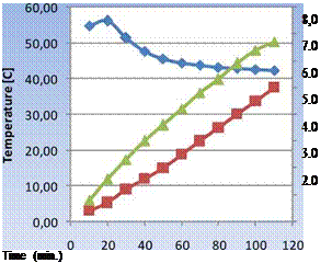
Simultaneous charging and discharging of the storage could be of importance in certain system configurations. This has also been examined and one set of experimental results are shown in Fig. 6.
Fig. 6. Simultaneous charging and discharging of HEATPACK initially at 50 °C. Charging temperature and flow rate 70 °C and 0,15 m3/h, respectively. Discharging temperature and flow rate 13 °C and 0.10 m3/h, respectively.
Here, the tank is initially not fully charged, with and average PCM temperature at 50 °C. Part of the PCM is molten whereas other sections are still in solid form. The storage was then continuously charged with 70 °C water flowing at 0.15 m3/h, and simultaneously discharged by water at approximately 13 °C, flowing at 0.10 m3/h. As shown, the hot water temperature leaving the storage had a usable temperature of over 40 °C for over two hours.
In the heating central heat flow meters are installed in every circuit. Additional temperature sensors allow for measurement of flow and return temperatures to or from buffer store (B), heat pump (HP) and vessel (V), see Fig. 8. At the heat exchanger between the circuit of the store and the collector field anti-fouling units are installed. The effectiveness of the anti-fouling device is determined by monitoring the heat transfer coefficient (UA) of two identical heat exchangers, one with and one without the anti-fouling electrode. A meteorological station allows the monitoring of the ambient temperature, the irradiation, and wind velocity.
The store and the surrounding soil are equipped with several Pt100 temperature sensors, see Fig. 9. Additionally, heat flux sensors are placed at several locations in the envelope of the store in order to determine the local thermal losses. The hydraulic behaviour at charging and discharging via the two wells with regard to vertical and horizontal stratification will be one of several investigations. CFD simulations will be conducted in order to be able to improve the concept furthe.
Special attention needs to be paid to the situation that the ground water level is just below the store. Increased thermal losses in comparison to locations without ground water are expected. Hence, one focus of the monitoring will be the determination of the effect of ground water (flow) on the thermal losses. Ground water level, temperature, flow velocity and direction will be additionally monitored. Three wells will be installed that allow for the continuous determination of ground water velocity, level and temperature. A thermal response test is planed in order to determine the soil properties (thermal conductivity, thermal diffusivity).
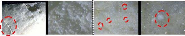
Test 2 shows a different distribution of the PCM, the majority is at the insulated surface of the sandwich panel, but also small areas with PCM at the middle of the sandwich panel were found, see Figure 6 (a) and (b).
|
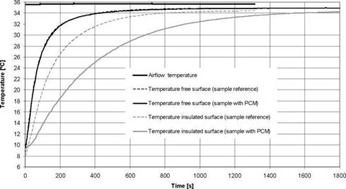
Figure 7, shows the reference sample and the sample with PCM, where thermal performance results show a higher delay on the insulated surface, this effect is expected using the PCM (increase thermal inertia). The reference sample and sample with PCM (free surface) had an equal behaviour.
(a) (b) (c) (d) |
|
Figure 6 Test 2 (a) Sandwich panel with PCM (b) Zoom of the sample with PCM. Test 3 (c) Sandwich panel with PCM (d) Zoom of the sample with PCM
|
Figure7 Thermal performance test of the reference sandwich panel and sandwich panel with PCM (Test 2)
Table 2 shows the adhesion results of test 1, test 2 and test 3. In all tests the reference sample are within or close of the limits (0.1 MPa the minimum load for adhesion test in sandwich panels) and the sandwich panel results with PCM (test 2) are far below the limit.
M. Belusko *
Institute for Sustainable Systems and Technologies, University of South Australia, Australia
Corresponding Author, martin. belusko@unisa. edu. au
Abstract
Chilled beam systems for sensible cooling enable the use of high temperature heat sinks. The use of cooling towers as a heat sink has significant advantages in dry climates due to the high coefficient of performance of these systems. However, this approach tends to only work during mild conditions due to the high wet bulb temperatures experienced in hot weather. Integrating thermal storage into the system, in which water is cooled by the cooling tower at night for use in the chilled beam system during the day, makes use of the significantly lower dry and wet bulb temperatures experienced at night. Variations of this concept have been trialled but no investigation has been made into this concept for multi storey buildings. A simulation in TRNSYS of this concept was conducted and compared to a conventional chiller system cooled by a cooling tower. Significant savings in energy and meaningful savings water were identified for most medium to high capacities of thermal storage. For a building with a floor area of 8000 m2, a storage volume of 2000 m3 would achieve a saving in energy and water of at least 50% and 12% respectively.
Keywords: chilled beam, cooling tower, thermal storage
Chilled beam technology has proved an effective technology at delivering sensible cooling in commercial buildings [1]. The ability to utilise 15 — 18 oC water as the heat sink instead of the typical 6 — 7 oC has increased the coefficient of performance of chiller systems and enabled the use of low energy heat sinks such as cooling towers [2].
Cooling towers provide a cooling potential which is defined by the wet bulb temperature. There are many climates in which the wet bulb is such that chilled water at 15-18 oC is achievable. Given that cooling towers can have a coefficient of performance (COP) of the order of 40 to 60, sensible cooling loads can be significantly reduced with this arrangement. This concept was investigated for UK conditions where cooling loads are generally mild, and it was shown that a significant portion of the cooling load is possible, but not during hot conditions [2]. This method was investigated further through optimisation of cooling tower operation [3]. The performance of the cooling tower is often defined by the approach, the temperature difference between the chilled water leaving the tower and the inlet air wet bulb temperature. It was shown that a cooling tower can be optimised and achieve low approaches of 1-4 oC. However, it was also presented that even the 2 percentile design wet bulb temperatures for most European cities are 17 oC, meaning a cooling tower cannot be used in hot conditions. In semi arid climates such as southern Australia, summer conditions are dry and hot with sensible cooling the dominant cooling demand. Although an ideal candidate for cooling tower driven chilled beam systems, average wet bulb temperatures are also typically around 16 — 18 oC during cooling periods. Therefore, the scope for sensible cooling using cooling towers is limited to mild cooling load periods.
To make use of this method of cooling for hot periods, an alternative approach is proposed involving thermal storage. Particular in dry climates night time dry bulb and wet bulb temperatures are significantly lower than day time temperatures. Therefore operating a cooling tower at night when most commercial buildings are idle, and storing this chilled water for day time use, may achieve the required chilled water temperatures for chilled beam applications. Variants of this method have been trialled in large commercial buildings in Australia. The Council House Building for the Melbourne city council (CH2 building) applied shower cooling towers in combination with conventional cooling towers operating at night to store cooling in phase change materials which would be used in a chilled ceiling system during the day. This project combined a number of novel technologies, however the cooling system was unable to achieve low enough temperatures to charge the phase change system [4]. Another system, implemented in a 2 storey building in Melbourne (Kangan Batman TAFE building), consists of a 130 m3 water tank for the chilled ceiling system. A night time roof spray cooling method was applied for cooling the water [5]. Adequate water temperatures were achieved and the system was designed to meet the bulk of the cooling load. Due to a roof spraying system having a low cooling capacity this technology cannot be implemented in a multi storey building. Although roof spray systems can produce lower temperatures than cooling towers as they also utilise radiative cooling, the system demonstrates the effectiveness of storage of night time water subject to evaporative cooling.
Cooling towers are not only existing infrastructure and available for use, but also have a high cooling capacity. Secondly, particular in the Australian case, due to water conservation issues and/or peak power requirements, large storage tanks are becoming a standard feature of new commercial buildings. This trend is of particular relevance to buildings attempting to achieve high ecological ratings since cooling towers are generally the biggest consumer of water in a commercial building. Therefore the proposed system may prove a low cost solution. Consequently, a study is warranted to investigate the use of cooling towers operating at night in combination with large storage tanks to drive chilled beam systems during the day. The principle advantage of storage is that rather than providing cooling during mild conditions, cooling can be delivered during extreme conditions which reduces peak power and can improve the overall COP of the chiller system.
An additional advantage of night time operation of the cooling tower is that water temperatures below 20 oC are produced. Legionella, a major concern of cooling tower operation, does not readily grow at these temperatures [6]. Therefore, if a system was developed in which the cooling tower is dedicated to night time operation, the need for chemical treatment could be eliminated. For daytime systems as presented in [3], the chilled water for the chilled beams is usually cooled through a heat exchanger with the cooling tower water to prevent any transfer of Legionella into the chilled beam water. As investigated in [3] this heat exchanger reduces the overall effectiveness of the system. Therefore, by working with lower temperatures this additional heat exchanger may be made redundant and the cooling tower water can directly be used within the chilled beam system.
As highlighted in [3], a principle concern of using a cooling tower at low dry and wet bulb temperatures is the resultant lower cooling driving force. Therefore greater heat and mass transfer is required to achieve the same level of cooling. This results in increased energy usage of the fan as well as greater water usage through evaporation. However, by operating the tower at night sensible cooling of the cooling water is achieved. Furthermore, a cooling tower providing direct cooling to the building, no longer needs to remove the heat of the compressor, as occurs in conventional cooling tower operation. Therefore, potential exists for an overall water saving. This paper presents a simulation of this system for Adelaide, a semi arid city in Australia.