Как выбрать гостиницу для кошек
14 декабря, 2021
Сегодня каждый, кто собирается в отпуск и не знает, с кем оставить своего котика или кошку, может во[...]
In a previous study, a modular thermal storage was studied under constant-temperature charge
conditions [3]. These results, although uncharacteristic of the normal operation of a typical solar system, illustrate the level of stratification possible in multi-tank configurations. To conduct this evaluation, an experimental rig was constructed and instrumented, allowing the time/temperature
|
3 I 2 3 Q. c 1 I 0 |
|
5 10 15 Time (hour) |
|
(a) Case A (b) Case B (c) Case C Fig. 3. Radiation profiles used in experimental sequence. |
 |
history within the storage to be recorded, Fig. 2 [4]. To record vertical temperature profiles, an array of thermocouples was inserted into each storage tank at 0.15 m intervals. During testing, a computer based data acquisition (DA) system was used to record and display storage and heat exchanger temperatures in real time. For the current study, this apparatus was modified to allow the simulated solar input power to be adjusted according to prescribed charge sequences, Fig. 3.
3.0 Experimental Results
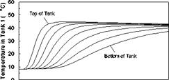
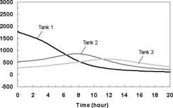
Constant Temperature Charge Sequences. A previous study [3] investigated the response of both series and parallel connected multi-tank storages to constant temperature charge sequences. For reference and comparison, typical results for the series connected case are shown in Figs.4 and 5 for a supply temperature of 46oC and a collector-loop flowrate of 1.5 L/min. (0.024 kg/s). The rate of heat transfer measured across each of the heat exchangers is shown in Fig. 6. Results indicated that sequential stratification was achieved during the constant temperature charge sequences [3] i. e., during charging, the first storage would initially charge, followed by the downstream storages in sequence. Under these test conditions, there was minimal carry-over of heat from the high temperature storage to the lower temperature, downstream storages. Constant charge temperatures, however, are not typical of the normal operation of a solar system where the thermal input typically rises in the morning and falls in the afternoon. These falling collector fluid temperatures may result in destratification.
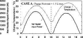
Variable Input Power Charge Sequences. In an effort to measure the unit’s thermal performance and temperature profiles under specified charge conditions, laboratory tests were conducted on the series-connected prototype [5]. For this study, a series of multiple-day radiation profiles were simulated. Using a computer controller, an electric heater was adjusted to provide the desired power output at any time throughout the day. The shape of the radiation profiles was chosen to represent the power output of a fixed solar array oriented directly at zero azimuth. As an approximation of these profiles, a sine function was applied to the output control signal as shown in Fig. 3. In particular, three test sequences were studied, Figs. 3(a), 3(b) and 3(c), corresponding to three hypothetical test cases, i. e., Cases A, B and C, respectively. Case A consisted of two consecutive clear, sunny days; Case B consisted of one clear, sunny day followed by one overcast day and Case C consisted of one overcast day followed by one clear, sunny day. The clear days provided a maximum input to the storage of 3000 W, while an overcast day peaked at 1500 W. Sunrise to sunset consisted of 10 hours in both cases. In order to reduce testing time, nighttime periods were removed from the test sequence as shown below. Typical results for the above charge sequences are shown in Figs. 7 to 15 for a collector-loop flowrate of 1.5 L/min. (0.024 kg/s).
The net heater input power and corresponding charge temperatures for each of the test sequences are shown in Figs. 7, 10 and 13, for Cases A, B, and C, respectively. As expected, for all cases, the temperature of the fluid feeding the first heat exchanger (i. e., the charge temperature) is seen to follow the input power profile, rising in the morning and falling in the afternoon. For Case A, the charge temperature on the second day is higher than that of the first day and the net power input is slightly lower. This is due to the fact that on Day 2, the tanks are at a higher temperature than on Day 1, thus requiring the charge loop to reach a higher temperature to facilitate further charging of the storage. This effect is even more evident in Fig. 10 where the charge temperature on the second day is considerably higher than would be expected at lower input powers.
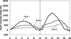
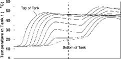
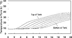
The temperature profiles recorded in each of the storage tanks are shown in Figs. 8, 11 and 14 for the corresponding charge sequences. Referring to these figures, it is immediately evident that, although the temperature profiles resemble the previously recorded constant temperature charge case, Fig. 5, subtle differences exist. For example, in Fig. 8, the temperature profiles of the first day closely resemble those of Fig. 5 during the morning period; however, at hour six of the test, the temperatures at the top of the tank converge in Tank 1 due to falling charge temperature occurring at that time. As shown in Fig. 9, this sequence of events is consistent with the decrease in heat transfer rate across the heat exchanger at Tank 1, which goes to zero by hour eight.

|
4000 3500 3000 2500 2000 1500 1000 500 0 |
|
Net Heater Power Input (W) |
|
|
|
|
|
Heat Transfer Rate (W) |
![]()
|
Time (hour) Fig. 5. Temperature profile of storage tanks during charging for constant temperature test. |

|
Fig. 6. Individual charge rates across each heat exchanger for constant temperature test. |

|
each heat exchanger for 2-day high input power test. |
 |
Time (hour)
Fig. 8. Case A: Temperature profile of storage
tanks during charging for 2-day high input power test.
|
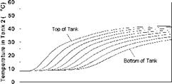
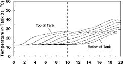
Time (hour) Fig. 11. Case B: Temperature profile of storage tanks during charging for 2-day high/low input power test. Fig. 12. Case B: Individual charge rates across each heat exchanger for 2-day high/low input power test. |
|
Fig. 10. Case B: Net heater input power and charge temperature for 2-day high/low input power test. |
|
Time (hour) Fig. 13. Case C: Net heater input power and charge temperature for 2-day low/high input power test. |
|
4000 3500 ■ 3000 j 2500 ■ 2000 j 1500 ‘ 1000 ; 500 0 |
|
Net Heater Power Input (W) |
 |
 |
 |
 |
Time (hour)
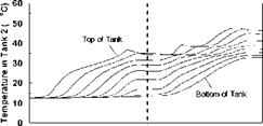
Fig. 14. Case C: Temperature profile of storage
tanks during charging for 2-day low/high input power test.
|
|
Time (hour)
Fig. 15. Case C: Individual charge rates across each heat exchanger for 2-day low/high input power test.
Also evident in Fig. 9 is that due to limited heat exchanger capacity, a portion of the total energy transferred to the storage is transferred across the heat exchangers of Tanks 2 and 3. The heat transferred to Tank 2 is seen to increase during the day as the charge level in Tank 1 increases, finally reaching a maximum at hour eight, as the charge temperature drops below the temperature of Tank 1. Later in the day, as the charge temperature drops even further, Tank 3 takes up the charge. Although the top section of the Tank 1 in Fig. 8 is seen to remain at a fairly uniform temperature between hours eight and thirteen (corresponding to the period when the natural convection flowrate goes to zero), it is evident that the temperatures within the storage tank are slowly reducing due to standby heat losses or reverse thermosyphoning. Careful examination of Fig. 9 for the corresponding period shows that the heat transfer rate across the first heat exchanger is slightly negative indicating that some heat is being removed from Tank 1 and transferred to the downstream heat exchangers. While undesirable, the magnitude of this effect appears to be small. As well, in a typical solar heating system, the differential temperature controller would have normally shut off the circulation pump at this time.
With the onset of Day 2, the charge temperature increases and heat is initially transferred to Tank 3 which is at the lowest temperature. As the charge temperature rises throughout the day, Tanks 2 and 1 accept further charging. At the midpoint of the second day, the charge temperature is high enough that the majority of the heat input goes to Tank 1. The net result of this sequence of events is that the storage system is observed to be directing the energy input to the tank with the closest temperature distribution. In this way, sequential stratification is passively maintained. This process, however, is not perfect, as there is a small degree of carry-over from the high temperature storage to the downstream storage tanks.
The capability of the storage system to direct energy to the storage tank at the appropriate temperature is further illustrated in Figs. 11 and 14 for the Case B and C charge sequences. In particular, referring to the temperature profiles for Tank 1, it may be observed that none of the heat input from Day 2 is directed to Tank 1 for Case B whereas the majority of the heat input is directed to Tank 1 for Case C. This results because the charge temperatures are too low to successfully charge Tank 1 for Case B and above the tank temperature in Case C. As well, the rate of heat transfer measured across each of the heat exchangers is shown in Figs. 9, 12 and 15, and illustrates the sequential charging of the storage unit, i. e., Tank 1 initially charges, followed by Tanks 2 and
2. Lastly, Figs. 16 to 19 show the temperature profiles and charge rates of a series and parallel connected multi-tank system as measured for a charge flow of 4.5 L/min (0.072 kg/s). The similarity of the temperature and energy rates is evident.
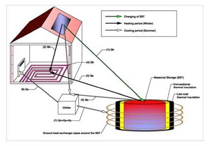
The innovation with the High-Combi system, examined in this paper, is the achievement of high solar fractions in combination with relatively small SST. The original design of the system under investigation includes the solar heating and cooling plant and the SST coupled with ground heat exchangers (GHE) to minimize heat losses from the storage tank. The main system components of the installation are the solar thermal collectors (180 m[26] [27], selective flat plate), the heating/cooling elements (a combination of floor heating and fan coils2), the absorption cooling machine (35 kWc), the SST (200 m3) and the GHE. The simulated total building area is equal to 700m2 having space heating and cooling energy demands of about 40 and 45 kWh/m2 respectively.
A schematic of the High-Combi plant’s operation is illustrated in Figure 1. This configuration corresponds to one of the five pilot plants (the one to be constructed in Greece) in the framework of the High-Combi project.
The cooling machine is driven by the solar thermal energy (Qh or Qs) at a high temperature (i. e., 70- 90°C) from the SST3, and provides useful cooling by extracting heat (Qc) from the building. To keep the absorption process going, the latent heat from the absorber and the heat from the condensation of the desorbed refrigerant in the condenser, is rejected to the ground heat exchangers, positioned in the earth, around and concentric to the hot water storage tank. In this way, the earth surrounding the tank
will be heated, thus reducing the tank’s thermal losses. Currently, the ground heat exchangers (GHE) are not included in the simulated plant’s configuration and the heat rejection is accomplished through a cooling tower. The use of GHE will be investigated at a follow-up stage.
|
Figure 1. HIGH-COMBI schematic plant layout |
The plant’s operation can be described as follows: during summer, whenever an excess of solar energy is available, this excess heat is delivered directly into the water storage tank. The water in the tank may be heated up to almost 100°C in the summer. The combination of a good conventional thermal insulation and an additional low cost thermal insulation (composed of low cost materials, for example, empty plastic bottles and chipped tires[28]) will reduce the heat losses from the SST, extending its use into the winter months and potentially cover a substantial amount of the heating loads (reaching even 100%). During winter, part of the heating load will be covered directly by the solar heat gains.
At a first glance, it seems contradictory to make a small SST, compared to the conventional ones that are of the order of at least some thousand cubic meters. Thermal losses from the heat storage are proportional to its envelope surface to volume ratio; this ratio increases as the volume becomes smaller. Thus, a smaller SST is expected to have higher thermal losses that need to be accounted for. On the other hand, the construction of a “small” sized SST is attractive since it will permit solar heating and cooling applications at a different scale.
Simulations made in this paper, show that there are still advantages against what might initially be regarded as unfavourable scale application. The use of a relatively low-temperature heat distribution system will allow using the stored heat at a wider range of supply temperatures. This will result to a higher amount of usable energy accumulated in the SST for the same storage volume, and to lower overall heat losses as the mean storage temperatures are reduced.
An overview of the simulation methods and results is presented in the following section.
The objective of this international collaboration is to develop advanced materials for compact storage systems. The systems will store thermal energy for renewable heating and cooling or for energy conservation.
The objective can be subdivided into six primary goals:
• to identify, develop, and test advanced materials for compact storage,
• to design and develop new materials or composites,
• to develop measuring and testing procedures to characterise these new materials reliably and reproducibly,
• to perform pre-standardisation work for advanced thermal energy storages,
• to develop and demonstrate novel compact thermal energy storage systems employing the advanced materials, and
• to disseminate the gained knowledge.
Because seasonal storage of solar heat is the main application for thermal energy storage, this field will have the focus of this task. However, other applications are also very important, including applications in both renewable energy and energy conservation technologies. Because of this, and because materials research is not and can not be limited to one application only, this task will not focus on only one application area. Other applications in renewable energy and energy conservation-such as solar cooling, micro-cogeneration, biomass, or heat pumps-will also be taken into account.
In terms of classes of materials, this task will be focused around three main classes:
• phase change materials, including micro — and macro-encapsulation and slurries,
• thermochemical materials, including sorption, and
• composite materials and nanostructures.
The latter category includes for instance the combination between zeolites and silicagels, and materials where the molecular and crystalline structure are engineered in detail. Production technologies, the ability to produce advanced materials on a large scale at reasonable costs, is an important aspect in all of these classes.
The task will be organised around the following main activities:
• material engineering: analysis and engineering of advanced materials, synthesis of new materials and composites, and materials characterisation and testing;
• numerical modelling: numerical modelling of materials, including molecular interactions, mass and heat transport phenomena, and bulk behaviour;
• components and systems: development, numerical modelling, and testing of (prototypes of) thermal storage components and systems that use the materials developed in the other activities.
The main challenge for this task is to bring together material experts and application experts (particularly solar applications, given the primary scope of the task). The active participation of both groups of experts is essential for this task. However, these groups are traditionally organised in different Implementing Agreements. ECES, Energy Conservation through Energy Storage, has a strong tradition in material research, while SHC, Solar Heating and Cooling, has a strong tradition in solar applications.
Because of the particular nature of this task, a collaboration between these two Implementing Agreements is essential. Hence, this task will take the form of a Joint Task between these Implementing Agreements.
On October 5, 2007, a first expert meeting was held in Zurich, Switzerland, followed by a Task Defintion Workshop in Petten, The Netherlands, on April 10-11, 2008. Both meetings were very well attended, not only by researchers, but also by representatives of European industries, both large and small. Based on these meetings, the outline of the new task’s objective, scope, and main activities were defined. In a subsequent expert meeting in Bad Tolz, Germany, on June 4-6, 2008, the topics of the task were discussed in more detail.
One of the conclusions of these meetings wass that the main value in this task is to actively combine the knowledge of experts from materials science as well as from solar/renewable heating and energy conservation. Hence, a strong co-operation with other IEA Implementing Agreements is essential to the success of the task, as already mentioned above. Another noteworthy conclusion of the meeting was the strong interest of industry in this task: the industry representatives at the meeting all agreed on the importance of the development of new storage materials.
In their respective ExCo meetings in May and June 2008, the new task was officially approved by both the SHC and ECES Executive Committees. The task will be designated as Task 42 in SHC, and as Annex 24 in ECES. Both ExCos were very positive on the scope and topic of this task. Wim van Helden of ECN, the Netherlands, and Andreas Hauer of ZAE Bayern, Germany, were appointed as Operating Agents.
The official starting date for this four-year task is January 1, 2009. Although four years is relatively long compared to other tasks in either SHC or ECES, this is warranted by the fundamental nature of the work in this task. Because the work on advanced storage materials is still in a very fundamental stage, the trajectory towards applications is still relatively long. It takes several years to identify, characterise and optimise the right materials or composites, and again to develop the reactors, proof-of-principles, and prototypes of the advanced storages made of these materials.
Experts from industries and research organisations worldwide, that are active in this field, are cordially invited to join this new task. If you are interested, please contact the authors of this paper or your national ECES or SHC ExCo member.
More information on this task can be found on the temporary task website at www. ecn. nl/ieamaterials.
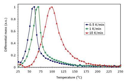
Several sources indicate that MgSO4.7H2O melts at a temperature range of 50-52.5°C during dehydration (see for example Refs [2, 7]). Melting is a problem, since it reduces the bed porosity of the material, and consequently the vapor transport through the bed, which limits the ability of the material to take up water again. The TGA-DSC curve for heating rate at 1 K/min (Figure 1) shows that for MgSO4.7H2O is completely converted to MgSO4.6H2O at 50°C and therefore no melting occurs.
However, if the heating rate is increased, the dehydration peak is shifted to higher temperatures due to kinetics. Figure 3 illustrates the effect of the heating rate on the dehydration peak:
|
Fig. 3. Influence of heating rate on the dehydration |
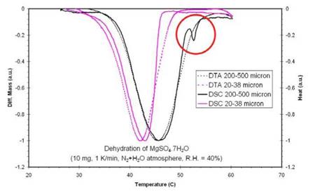
It means that for higher heating rates (> 1 K/min), MgSO4.7H2O may still be present at 50-52.5°C and starts to melt. The melting of MgSO4.7H2O was studied by a combined TGA-DSC measurement. This can be distinguished from dehydration since melting causes a heat uptake of the material without a change in mass as illustrated in Figure 4.
|
Fig. 4. Melting for large particles. The red circle denotes position of melting temperature of MgSO4.7H2O |
The results of the combined TGA-DSC experiments indicated that melting of MgSO4.7H2O typically occurred for high heating rates, large sample masses and/or large particles. The experiments also indicated that only melting of MgSO4.7H2O occurs during dehydration of the material.
The analytical analysis presented in this manuscript was made assuming the location Vagos, Portugal (40°32’42,18"N, 8°42’56,72"O) because this is the site where the prototype will be installed. Climate variables (solar radiation and temperature profiles) were obtained through the
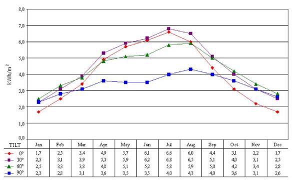
SolTerm data base [1]. In this region, the minimum average temperature is 9,0°C in December and 19,7°C of maximum average temperature in July. Global solar radiation in the horizontal plane varies from a minimum of 1,7 kWh/m2 in December to a maximum of 6,6 kWh/m2, registered in July. Figure 1 presents the solar radiation profile as function of the angle of the solar collector with the horizontal.
|
Fig. 1. Solar radiation profile as function of the solar panel tilt. |
Radiation profile presented in Figure 1 was obtained by applying the correction factor only to the direct radiation in spite of the fact that the diffuse radiation, coming on days with clear sky, is not uniformly distributed over the hemisphere but concentrated in the direction of the sun. Correction factor R was defined as Rd = cos 0 / cos 0z, where 0 represents the angle of the solar radiation with the normal of the panel and 0z the angle of the solar radiation with the vertical of the location.
The FTIR spectral analysis did not prove generation of chemical products during crystallization process of the Composite 3, but two peaks on DSC solidification curve of the Composite 3 (Fig.1) would suggest that the inhomogeneous structure was formed during crystallization process. Additionally the DSC curve of the Composite 2 (Fig.1) showed bigger temperature hysteresis of 4 degrees, while the subcooling is of 3 degrees. DSC results merely defined needs of more detailed further research and analysis of the composite structure. Next correlation between thermal and structural properties initiated observations of inhomogeneous fragments of the novel salt/graphite composites structures, well exemplified with SEM images below. (Table 3.).
The inhomogeneous composite structure shows inhomogeneous salt crystal distribution, salt/graphite clustering, untypical salt crystal formation caused by uncontrolled nucleation frequency and crystallization growth rates of the NaNo3/KNO3eutectics — important factors responsible for structural stability of the composite
|
Inhomogeneous salt crystal distribution |
|
Uncontrolled salt |
|
Salt/graphite clusters |
 |
 |
 |
Table 3. Inhomogeneous structural fragments of NaNO3/KNO3eutectics/graphite composites.
1.2 Measurement set-up
On the basis of simulation results and available air heater capacities an experimental heat exchanger set-up with nominal heat flow of 15 kW, maximum air inflow temperature of 800 °C and dimensions of 0.5 m height,
0.05 m width and depth of 0.1 m was designed and manufactured. The sand inflow and outflow were extended by ducts of 0.5 m height to reduce air leakages. The crucial elements of the heat exchanger are two porous walls for filtration of air at the air entrance and exit.
Fig. 3 Experimental air-sand heat exchanger unit
The filtering walls have to meet various requirements including
• Abrasion resistance for continuous sand flow
• Thermal stability up to 800 °C
• Low pressure drop
In view of the two requirements mentioned first, recrystallized silicon carbide (RSiC) was chosen as wall material.
For calculation of heat transfer, heat losses and blower energy demand volume flows, air pressure drop and air and sand temperatures were measured at different positions.
|
v0§CR (t) = . ^stored (t) • 100% |
|
I |
|
^ delivered, MAX (t) ^deliveredMAX (t2 ) ^delivered, MAX (t1 ) |
|
deliveredMAX |
|
(t) = ■ |
|
12 t1 |
|
I |
|
d elivered, MAX |
|
(t) Edelivered (t) |
|
E |
|
delivered |
|
T — T delivered 0 J |
|
(t) V lnr T |
|
delivered |
|
T T0 J |
|
(7) (7) (9) |
For practical closed-loop applications, special consideration must be given to the flow rate limitations of the system. This is to be expressed by an additional index, the Operational Exergy Charge Reponse (цо&я), whereby:
t
|
(10) |
![]() Edelivered (t) = Eavail(t) dt
Edelivered (t) = Eavail(t) dt
0
Edelivererd is a representative of a given day’s energy profile. The maximum exergy associated with the energy profile is subject principally to an upper temperature limit, Tdelivered. This can be the desired delivery temperature of the TES, the system’s stagnation temperature, or the working fluid’s boiling temperature. By applying the цо^ск to the fully stratified TES, one may gather a better indication of the exergy potentially lost due to the system’s flow rate limitations.
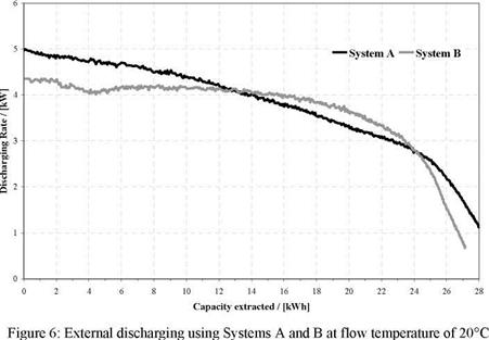
Complete external discharging takes about 5 to 9 hours, depending on discharging temperature and discharging flow. Choosing a flow temperature of 20°C, discharging is possible at an average of 3 kW. At the end there were no significant differences detected between the two types of heat exchangers (Figure 6).
|
|
2.2
|
![Подпись: System A System B Discharging Temperature [°C] 20 22 24 Internal 20 20 22 24 Internal 20 Average Mass Flow [kg/s] 0,319 0,319 0,319 0,252 0,319 0,319 0,319 0,270 Average Mass Flow in Store [kg/s] 0,084 0,95 0,104 - 0,085 ** ** - Average Discharging Rate [kW] 3,33 4,11 4,99 4,34 3,34 ** ** 2,47 Effective Capacity [kWh ]_ 28,55 28,81 28,01 27,33 26,86 ** ** 29,23 Period of Discharging [min] 514 420 337 370 482 ** ** 710](/img/1128/image627.gif) |
Heat losses
No significant losses of cooling energy were measured. At an ambient Temperature of 23°C, loss of cooling energy in 24 hours is about 1 kWh. This means an average rate of loss of about 42 W.
With an increasing share of power generated by renewable energy sources, fluctuations in grid power supply due to varying solar radiation or varying wind speeds are increasing, too. Unlike many other renewable energy technologies solar thermal power plants can supply power dependent on the demand using thermal energy storages.
In central receiver systems/solar power towers with open volumetric receiver air is sucked through a porous structure (absorber), which is heated by concentrated solar radiation. By this the air is heated up to 800 °C. In normal operation the air heat is used to run a steam cycle for power generation in a conventional steam turbine-generator system. During periods with excess of solar energy a part of the air current can be also used to charge a thermal storage.
For high-temperature storage up to approximately 800 °C systems using packed beds of ceramic bodies or ceramic bricks have been analysed so far. These storage systems are featured by a simple configuration, but involved with higher costs for the storage material.
In view of storage material costs the sand storage concept for solar power towers with open volumetric receiver has been developed, as shown in Fig. 1:
[12] Introduction
Phase change materials offer a great potential for energy saving in cooling applications as well as efficient energy storage at different temperature levels. Commercially available applications of PCM are e. g. passive solid materials which are used in building walls to shave temperature peaks in the afternoons and are recooled by outside air during the night [1]. In active cooling applications, the material is integrated in storages, e. g. encapsulated water (ice storage) or paraffin panels and the refrigerant medium circulates around it thus withdrawing or releasing energy [2, 3].
By contrast Phase Change Slurries are emulsions or suspensions of PCM which circulate in the heat/cold network. So the energy is taken directly to the consumer (e. g. chilled ceiling). This technology has the advantage that the problem of slow heat transmission due to the poor heat transfer coefficients and low thermal conductivity of pure macroencapsulated PCM is reduced significantly. The disadvantage is the higher viscosity which can cause problems with small pipe diameters.
Presently PCS are used on major scale only in Japan [4]. There mainly ice-slurries are employed — a suspension of liquid and frozen water with additives preventing the accumulation of ice particles. With
[14] During the cooling process of PCM the initiation of crystallization, usually requires temperatures well below the melting point. This temperature difference is called subcooling.
[15] Q = dt*m*cw =14 °C * 500kg * 1,16Wh/kg = 8,12kWh
[16] V. M. van Essen, H. A. Zondag, R. Schuitema, W. G.J. van Helden, C. C.M. Rindt (2008), Materials for thermochemical storage: characterization of magnesium sulfate, Proceedings Eurosun 2008.
[17] A. N. Kalbasenka (2008), Basis calculations of reactor concepts, ECN memo Acknowledgement
This project has received financial support from the Dutch Ministry of Economic Affairs by means of the EOS support scheme. The work on thermochemical heat storage is part of the long-term work at ECN on compact storage technologies.
[18] Introduction
A novel solar powered 10 kW absorption chiller was developed and tested at the ITW in recent years. To extend the hours of operation and to achieve a high chiller efficiency for air conditioning purposes, a small ice store was designed, constructed and experimentally investigated.
The ultimate aim of this project is to offer an efficient and commercially viable solution for solar driven cooling of small residential and commercial buildings such as single occupancy houses and small office buildings. In a first series of measurements several of the offices of the Institute of Thermodynamics and Thermal Engineering (ITW) of the University of Stuttgart are cooled by a
[21] A. Hauer, Beurteilung fester Adsorbentien in offenen Sorptionssytemen fur energetische Anwendungen, Doctoral Thesis, Technische Universitat Berlin, Fakultat III Prozesswissenschaften, 2002.
[22] E. Lavemann, A. Hublitz, M. Pelzer, Betriebsergebnisse einer solarunterstutzten Flussigssorptionsanlage in Singapur (German), Proceedings 4th Symposium „Solares Kuhlen in der Parxis“, Stuttgart, April 3-4, 2006.
[23] The term “total solar fraction” is defined by the following equation: SFtotal = 1 — Eaux/Edemand. where Eaux is the
energy supplied from the auxiliary heater and Edemand is the sum of the energy needed to meet the heating and
cooling thermal comfort in the building and the energy to heat up the domestic hot water.
[26] Floor space heating has proved to be much more effective (compared to fan-coils) in terms of solar system efficiency. Most probably the floor elements will prove to increase the system’s efficiency furthermore, if they are used for cooling as well. However, since “floor cooling”, in order to be effective, needs some dehumidification device (and, consequently, complicated controls and simulations), we have chosen to use conventional fan-coils for cooling in summer. The “floor cooling” configuration (perhaps with a limited number of fan-coils for dehumidification) seems very promising and is, at the moment, under investigation.
[27] Currently, for the simulations there is no possibility to bypass the SST and deliver energy directly from the collectors to the chiller. However, this bypass could increase system’s performance and should therefore be implemented as the optimization procedure evolves.
[28] In the framework of High-Combi, the use of low cost materials as additional insulation of the SST has been investigated by laboratory measurements. The experimental results will be available soon in the project’s web site.
[29] One may argue that some winters may be more severe (or have less solar radiation) than others and, therefore, an auxiliary boiler is needed. In order to handle such fluctuations the solution is a slight increase the collectors’ field area.
[30] By fully charging the DHW tank: i) some energy is taken away from the SST, and ii) there is a reduction of the collectors’ efficiency (compared with their efficiency when charging the SST), due to the higher operating temperatures. However, the amount of energy lost by the SST in order to achieve 100% solar fraction for DHW is about 720 kWh and may, therefore, be achieved with an addition of a few (about 2) m2 of solar collectors.
[31] Higher solar fraction
Most Danish natural gas fuelled CHP-plants are now operating in a free electricity marked, where one of the main sources of income comes from regulation of electricity production. The regulation is needed because of a large fraction of windmill produced electricity in the Danish system.
That means normally less running hours for the engines and 25-50% of the heat produced in a natural gas boiler. Natural gas is an expensive fuel that very often means production prices of more than 60 €/MWh.
Therefore solar heat is an attractive alternative, but if the solar fraction exceeds app. 10%, the accumulation tank is too small for electricity regulation. The CHP-plants are thus eager to find solutions making it possible to increase the solar fraction and at the same time keep the regulation possibility. In the following 4 new projects with higher solar fraction are described.