Как выбрать гостиницу для кошек
14 декабря, 2021
Сегодня каждый, кто собирается в отпуск и не знает, с кем оставить своего котика или кошку, может во[...]
In a previous study, a modular thermal storage was studied under constant-temperature charge
conditions [3]. These results, although uncharacteristic of the normal operation of a typical solar system, illustrate the level of stratification possible in multi-tank configurations. To conduct this evaluation, an experimental rig was constructed and instrumented, allowing the time/temperature
|
3 I 2 3 Q. c 1 I 0 |
|
5 10 15 Time (hour) |
|
(a) Case A (b) Case B (c) Case C Fig. 3. Radiation profiles used in experimental sequence. |
 |
history within the storage to be recorded, Fig. 2 [4]. To record vertical temperature profiles, an array of thermocouples was inserted into each storage tank at 0.15 m intervals. During testing, a computer based data acquisition (DA) system was used to record and display storage and heat exchanger temperatures in real time. For the current study, this apparatus was modified to allow the simulated solar input power to be adjusted according to prescribed charge sequences, Fig. 3.
3.0 Experimental Results
Constant Temperature Charge Sequences. A previous study [3] investigated the response of both series and parallel connected multi-tank storages to constant temperature charge sequences. For reference and comparison, typical results for the series connected case are shown in Figs.4 and 5 for a supply temperature of 46oC and a collector-loop flowrate of 1.5 L/min. (0.024 kg/s). The rate of heat transfer measured across each of the heat exchangers is shown in Fig. 6. Results indicated that sequential stratification was achieved during the constant temperature charge sequences [3] i. e., during charging, the first storage would initially charge, followed by the downstream storages in sequence. Under these test conditions, there was minimal carry-over of heat from the high temperature storage to the lower temperature, downstream storages. Constant charge temperatures, however, are not typical of the normal operation of a solar system where the thermal input typically rises in the morning and falls in the afternoon. These falling collector fluid temperatures may result in destratification.
Variable Input Power Charge Sequences. In an effort to measure the unit’s thermal performance and temperature profiles under specified charge conditions, laboratory tests were conducted on the series-connected prototype [5]. For this study, a series of multiple-day radiation profiles were simulated. Using a computer controller, an electric heater was adjusted to provide the desired power output at any time throughout the day. The shape of the radiation profiles was chosen to represent the power output of a fixed solar array oriented directly at zero azimuth. As an approximation of these profiles, a sine function was applied to the output control signal as shown in Fig. 3. In particular, three test sequences were studied, Figs. 3(a), 3(b) and 3(c), corresponding to three hypothetical test cases, i. e., Cases A, B and C, respectively. Case A consisted of two consecutive clear, sunny days; Case B consisted of one clear, sunny day followed by one overcast day and Case C consisted of one overcast day followed by one clear, sunny day. The clear days provided a maximum input to the storage of 3000 W, while an overcast day peaked at 1500 W. Sunrise to sunset consisted of 10 hours in both cases. In order to reduce testing time, nighttime periods were removed from the test sequence as shown below. Typical results for the above charge sequences are shown in Figs. 7 to 15 for a collector-loop flowrate of 1.5 L/min. (0.024 kg/s).
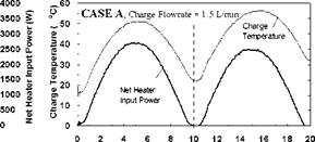
The net heater input power and corresponding charge temperatures for each of the test sequences are shown in Figs. 7, 10 and 13, for Cases A, B, and C, respectively. As expected, for all cases, the temperature of the fluid feeding the first heat exchanger (i. e., the charge temperature) is seen to follow the input power profile, rising in the morning and falling in the afternoon. For Case A, the charge temperature on the second day is higher than that of the first day and the net power input is slightly lower. This is due to the fact that on Day 2, the tanks are at a higher temperature than on Day 1, thus requiring the charge loop to reach a higher temperature to facilitate further charging of the storage. This effect is even more evident in Fig. 10 where the charge temperature on the second day is considerably higher than would be expected at lower input powers.
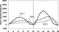
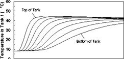
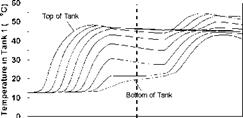
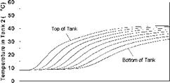
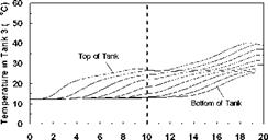
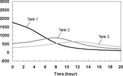
The temperature profiles recorded in each of the storage tanks are shown in Figs. 8, 11 and 14 for the corresponding charge sequences. Referring to these figures, it is immediately evident that, although the temperature profiles resemble the previously recorded constant temperature charge case, Fig. 5, subtle differences exist. For example, in Fig. 8, the temperature profiles of the first day closely resemble those of Fig. 5 during the morning period; however, at hour six of the test, the temperatures at the top of the tank converge in Tank 1 due to falling charge temperature occurring at that time. As shown in Fig. 9, this sequence of events is consistent with the decrease in heat transfer rate across the heat exchanger at Tank 1, which goes to zero by hour eight.

|
4000 3500 3000 2500 2000 1500 1000 500 0 |
|
Net Heater Power Input (W) |
|
|
|
|
|
Heat Transfer Rate (W) |
![]()
|
Time (hour) Fig. 5. Temperature profile of storage tanks during charging for constant temperature test. |

|
Fig. 6. Individual charge rates across each heat exchanger for constant temperature test. |

|
each heat exchanger for 2-day high input power test. |
 |
Time (hour)
Fig. 8. Case A: Temperature profile of storage
tanks during charging for 2-day high input power test.
|
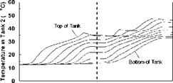
Time (hour) Fig. 11. Case B: Temperature profile of storage tanks during charging for 2-day high/low input power test. Fig. 12. Case B: Individual charge rates across each heat exchanger for 2-day high/low input power test. |
|
Fig. 10. Case B: Net heater input power and charge temperature for 2-day high/low input power test. |
|
Time (hour) Fig. 13. Case C: Net heater input power and charge temperature for 2-day low/high input power test. |
|
4000 3500 ■ 3000 j 2500 ■ 2000 j 1500 ‘ 1000 ; 500 0 |
|
Net Heater Power Input (W) |
 |
 |
 |
 |
Time (hour)
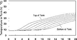
Fig. 14. Case C: Temperature profile of storage
tanks during charging for 2-day low/high input power test.
|
|
Time (hour)
Fig. 15. Case C: Individual charge rates across each heat exchanger for 2-day low/high input power test.
Also evident in Fig. 9 is that due to limited heat exchanger capacity, a portion of the total energy transferred to the storage is transferred across the heat exchangers of Tanks 2 and 3. The heat transferred to Tank 2 is seen to increase during the day as the charge level in Tank 1 increases, finally reaching a maximum at hour eight, as the charge temperature drops below the temperature of Tank 1. Later in the day, as the charge temperature drops even further, Tank 3 takes up the charge. Although the top section of the Tank 1 in Fig. 8 is seen to remain at a fairly uniform temperature between hours eight and thirteen (corresponding to the period when the natural convection flowrate goes to zero), it is evident that the temperatures within the storage tank are slowly reducing due to standby heat losses or reverse thermosyphoning. Careful examination of Fig. 9 for the corresponding period shows that the heat transfer rate across the first heat exchanger is slightly negative indicating that some heat is being removed from Tank 1 and transferred to the downstream heat exchangers. While undesirable, the magnitude of this effect appears to be small. As well, in a typical solar heating system, the differential temperature controller would have normally shut off the circulation pump at this time.
With the onset of Day 2, the charge temperature increases and heat is initially transferred to Tank 3 which is at the lowest temperature. As the charge temperature rises throughout the day, Tanks 2 and 1 accept further charging. At the midpoint of the second day, the charge temperature is high enough that the majority of the heat input goes to Tank 1. The net result of this sequence of events is that the storage system is observed to be directing the energy input to the tank with the closest temperature distribution. In this way, sequential stratification is passively maintained. This process, however, is not perfect, as there is a small degree of carry-over from the high temperature storage to the downstream storage tanks.
The capability of the storage system to direct energy to the storage tank at the appropriate temperature is further illustrated in Figs. 11 and 14 for the Case B and C charge sequences. In particular, referring to the temperature profiles for Tank 1, it may be observed that none of the heat input from Day 2 is directed to Tank 1 for Case B whereas the majority of the heat input is directed to Tank 1 for Case C. This results because the charge temperatures are too low to successfully charge Tank 1 for Case B and above the tank temperature in Case C. As well, the rate of heat transfer measured across each of the heat exchangers is shown in Figs. 9, 12 and 15, and illustrates the sequential charging of the storage unit, i. e., Tank 1 initially charges, followed by Tanks 2 and
2. Lastly, Figs. 16 to 19 show the temperature profiles and charge rates of a series and parallel connected multi-tank system as measured for a charge flow of 4.5 L/min (0.072 kg/s). The similarity of the temperature and energy rates is evident.