Как выбрать гостиницу для кошек
14 декабря, 2021
Сегодня каждый, кто собирается в отпуск и не знает, с кем оставить своего котика или кошку, может во[...]
The innovation with the High-Combi system, examined in this paper, is the achievement of high solar fractions in combination with relatively small SST. The original design of the system under investigation includes the solar heating and cooling plant and the SST coupled with ground heat exchangers (GHE) to minimize heat losses from the storage tank. The main system components of the installation are the solar thermal collectors (180 m[26] [27], selective flat plate), the heating/cooling elements (a combination of floor heating and fan coils2), the absorption cooling machine (35 kWc), the SST (200 m3) and the GHE. The simulated total building area is equal to 700m2 having space heating and cooling energy demands of about 40 and 45 kWh/m2 respectively.
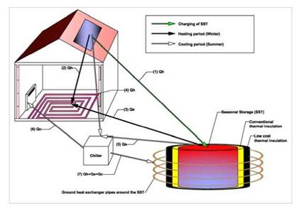
A schematic of the High-Combi plant’s operation is illustrated in Figure 1. This configuration corresponds to one of the five pilot plants (the one to be constructed in Greece) in the framework of the High-Combi project.
The cooling machine is driven by the solar thermal energy (Qh or Qs) at a high temperature (i. e., 70- 90°C) from the SST3, and provides useful cooling by extracting heat (Qc) from the building. To keep the absorption process going, the latent heat from the absorber and the heat from the condensation of the desorbed refrigerant in the condenser, is rejected to the ground heat exchangers, positioned in the earth, around and concentric to the hot water storage tank. In this way, the earth surrounding the tank
will be heated, thus reducing the tank’s thermal losses. Currently, the ground heat exchangers (GHE) are not included in the simulated plant’s configuration and the heat rejection is accomplished through a cooling tower. The use of GHE will be investigated at a follow-up stage.
|
Figure 1. HIGH-COMBI schematic plant layout |
The plant’s operation can be described as follows: during summer, whenever an excess of solar energy is available, this excess heat is delivered directly into the water storage tank. The water in the tank may be heated up to almost 100°C in the summer. The combination of a good conventional thermal insulation and an additional low cost thermal insulation (composed of low cost materials, for example, empty plastic bottles and chipped tires[28]) will reduce the heat losses from the SST, extending its use into the winter months and potentially cover a substantial amount of the heating loads (reaching even 100%). During winter, part of the heating load will be covered directly by the solar heat gains.
At a first glance, it seems contradictory to make a small SST, compared to the conventional ones that are of the order of at least some thousand cubic meters. Thermal losses from the heat storage are proportional to its envelope surface to volume ratio; this ratio increases as the volume becomes smaller. Thus, a smaller SST is expected to have higher thermal losses that need to be accounted for. On the other hand, the construction of a “small” sized SST is attractive since it will permit solar heating and cooling applications at a different scale.
Simulations made in this paper, show that there are still advantages against what might initially be regarded as unfavourable scale application. The use of a relatively low-temperature heat distribution system will allow using the stored heat at a wider range of supply temperatures. This will result to a higher amount of usable energy accumulated in the SST for the same storage volume, and to lower overall heat losses as the mean storage temperatures are reduced.
An overview of the simulation methods and results is presented in the following section.