Как выбрать гостиницу для кошек
14 декабря, 2021
The theoretical effort invested in modeling the CPV receiver with solar cells immersed in liquid has not seen the intensive research and development activity. The studies of thermal model of solar cells have been mostly concentrated on photovoltaic system and hybrid photovoltaic thermal system. Radziemska [9] summarizes the recent progress obtained in the field of the temperature performance of crystalline and amorphous silicon solar cells and modules. Various authors have modeled the temperature of a PV module by evaluation of energy inputs and outputs through radiation, convection, conduction and power generated. The energy balance of photovoltaic cells is modeled based on climate variables by Jones et al. [10]. Module temperature change is shown to be in a non-steady state with respect to time. A one dimensional heat transfer model was derived by Davis et al [11] to improve upon the NOCT model. Garg et al [12,13] have developed a computer simulation model for predicting the steady state and transient performance of a conventional photovoltaic/thermal (PV/T) air heating collector with single — and double-glass configurations. Lee et al. [14] concerns the development of a thermal model to predict the temperature profile of a typical building integrated PV roof and comparison of the performance of this model to that of the simplified model for flat-plate PV arrays presented by Fuentes.
In the present case, the energy flows among the elements of the CPV receiver and the surroundings are described in the thermal network drawn in Fig. 2. The goal of this network is to evaluate the solar cells temperature immersed in silicone oil. The solar cells temperature is critical to estimating the electrical production.
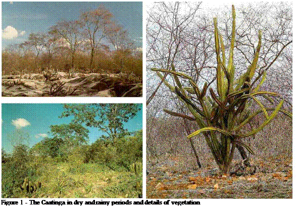
The Northeast of Brazil, made up of 8 states, represents 18% of the total area of the country, and is responsible for 16% of the production and it has a population of 42,000,000 people (28%). Approximately half of this area, 760,000 km2, is semi-arid where 17,000,000 people live. The climate of this region is hot and dry having a mean annual temperature of 27 °C and 2500 h/year of insolation. The annual precipitation varies from 400 to 800 mm, contrasting with an evapotranspiration of 2500 mm/year, which determines a dry period of more than 7 months. The vegetation that covers the semi-arid region is a deciduous tropical forest, locally known as the caatinga, that develops over a complex mosaic of soils, Fig.1. High level of insolation, scarce hydric resources and rare rainfall, poorly destributed over time, cause long periods of drought. Thus, the relative shortage of superficial hydric resources, make evident the importance of subterranean waters. The exploration of these waters is found to be limited because of the nature of its soils (predominanthy crystalline), low discharge rate ( mean of 3000 l/h) and mainly for its
 |
quality. The great majority of the wells present higher salinity indices than the maximum limit permitted for human consumption, that is of 1000 ppm of dissolved total solids and in many cases above 6000 ppm, the extreme water salinity level for animal consumption. Another aggravating factor that makes the solution to the problem of water supply difficult is the low index of rural electrification in the Northeast.
To face this kind of challenge, the Federal Government established the PRODEEM — Program of Energy Development for States and Municipalities through a presidential decree in December 1994, with the following objectives:
• Make viable the installation of energy microsystems for production and local use in isolated needy communities that are not served by electric network, that are destined to aid in attending basic social demands;
• Promote the utilization of decentralized energy sources in the supply of energy to the small producers, to nuclei of colonization and isolated populations;
• Compliment the conventional energy system offer with the use of decentralized renewable energy sources;
• Promote the utilization of human resources and development of technology and national industry, that are essential for implantation and operational continuity of the implanted systems.
Since the year 1996 the PRODEEM has bought and installed thousands of photovoltaic systems that are spread around the national territory. In the phases denominated I to V and a special one denominated Pumping, three kinds of autonomous photovoltaic systems were installed: photovoltaic systems for generation of electric energy (energetic), photovoltaic systems for
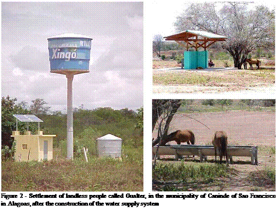 |
pumping water and for public illumination. The systems were only destined for application in communities, which means that they should benefit the communities as a whole, and not only some individuals in particular. The total of photovoltaic systems installed in this program was 8,956, corresponding to a total power of 5.2 MWe, and it can be considered as one of the largest rural eletrification programs that use photovoltaic solar energy in developing countries. Most of the photovoltaic systems were installed in the North Northeast regions, 1,471 and 4,577 systems respectively. In the target regions of this project AL, PE and PB 905 systems were installed, in accordance with the MME Eletric Energy Atlas (2008).
Fig. 2 shows the settlement of the landless people called Gualter, in the municipality of Caninde of Sao
Francisco in Alagoas, after the construction of the water supply system all supplied by photovoltaic solar
energy: the water supply system, the collective laundry and the drinking trough for animals. Fig. 3 shows
some other productive applications in community with photovoltaic solar energy: electrified fence and
school. The experience accumulated by the PRODEEM in the last ten years shows the enormous challenge
of management, planning, training and sociology of the implantation, on a large scale and in large territorial
extensions, of innovating technology and decentralized technology as of photovoltaic generation. The
traditional tools demonstrate their limitations and make the execution of such tasks very difficult.
L. Crema1*, G. Cicolini1, A. Bozzoli1
1 Renewable Energies & Environmental Technologies research unit (REET), Fondazione Bruno Kessler (FBK),
Via alla Cascata 56/C, I-38050 Povo (Tn), Italy
* Corresponding Author, :rema@,fbk. eu
In this work, we propose a solution to convection and conduction heat losses on an solar thermal collector. We have based our work starting from the technology of the evacuated solar tubes, the technology actually with the highest thermal efficiency in the market. The tubes have got a CERMET absorbing layer sputtered on the surface of a glass tube, in the evacuated area. A modified structure for the evacuated tube has been analysed in order to investigate the heat transfer and the thermal resistance from the cermet layer to the vector fluid in different fluid dynamic conditions than the actual used. Some models have been created and their behaviour has been verified using Finite Element Modelling software. The computed results show a lower thermal resistance for the proposed geometries. A higher convective heat transfer has been obtained providing the vector fluid of a turbulent flow, using special shapes (turbulators) applied to the evacuated tubes. The temperature gradient between the cermet layer and the vector fluid has been decreased from 20 to 1,06 K in the better case. The thermal efficiency of the panel has an improvement of about 10% from such modified geometry.
Keywords: solar collector, finite element modelling, fluid dynamic
During last years the development of new technologies have taken solar thermal collectors to new frontiers [1]. Collectors based on evacuated solar tubes, cermet layers and other applied technologies have taken good results. Many studies had proposed solutions to the evacuated solar tube development [2]. Nevertheless commercial collectors frequently suffer from some problems related to heat transfer phenomena, radiation loss at high temperatures or vector fluid choice. A relevant heat loss comes from conduction/convection phenomena between the absorber material and the vector fluid and from both of them to the environment. In the actual work it has been performed an analysis on a real evacuated solar tube with a relevant presence on the international markets and particularly good characteristics. The aim is to analyse aspects related to heat losses and to propose both a partial solution to the problem and a technical improvement of the system. The analysis will be performed under an analytical point of view, by the use of FEM (Finite Element Modelling) simulation and by an experimental setup for a direct verification of modelling.
The sensitivity analysis methods are divided in local and global ones. With local sensitivity analysis, the influence of parameters could be estimated only around a certain point in the parameters space. In the case of solar heating system, such an estimation is needed in a wider range of parameters
variations, in a certain volume of space. For this, two representatives of global sensitivity analysis are applied, namely the Morris method and the Fourier amplitude sensitivity test (FAST).
The models used for the parabolic trough collector fields are based on the model of Lippke [5] which has been developed for solar thermal power plants. The implementation of these models in Greenius has been described in [6]. The model parameters of the specific collector type have been measured at DLR and published in [7].
3. Comparison with another simulation tool
In order to validate the model for parabolic trough process heat plants, the simulation results shall be compared with measurements of a pilot plant which is just under construction in Ennepetal,
Germany. Therefore the validation of this model will be starting soon when sufficient data is available.
For the validation of the flat plate and vacuum tube collector models comparisons with the simulation program T*SOL have been made. A simple solar system for drinking water heating was used for this purpose. The system has a heat demand of 2700 kWh/a. In Greenius the operation mode “constant load” was used for the auxiliary boiler with a demand of 0.308 kW. A hot water storage of 0.3m3 was used as thermal storage. This storage has a thermal capacity of 17 kWh and a time constant of 250 hours. The flat plate collector Viessmann Vitosol 100 2.5s was used as solar collector. This collector has an aperture area of 2.5 m2 and a conversion factor of 0.8.
|
Fig. 2. Greenius screenshot |
The length of the pipes was 8 meters, 7 meters inside the building. The collectors were tilted 30° towards south. The location was Freiburg (Germany). A design temperature of 50 °C was chosen. The number of collectors was varied.
In general, since different models are used for the simulation a total conformity of the simulation results cannot be expected. In the current version Greenius does not have a stratification model for the thermal storage. The missing stratification leads to different temperature behaviour of T*SOL and Greenius. An adaptation can be made using different mean design temperatures. Therefore, the two design temperatures 45°C and 50°C have been considered in Greenius for the comparison. Figure 4 shows the system defined in T*SOL. Figure 3 shows the simulation results of T*SOL and Greenius with varying collector field size.
|
collector area in m2 Fig. 3. Comparison of the solar share with variation of the solar collector field size with different simulation runs using T*SOL and greenius |
Besides the missing temperature stratification in Greenius the different definitions of the solar share produce further differences. T*SOL additionally considers the storage losses when calculating the solar share, Greenius not. Therefore, the solar share calculated with T*SOL is a little higher than with Greenius. When considering the model differences between T*SOL and Greenius, the matching of the results is good.
The planning process for the insertion of renewable energies in rural areas is normally a complex task because it demands an approach with multiple criteria: energy resources, socio-economic
 |
 |
indicators, indices of non-electrification, among others. If we addiotinally consider the intention of stimulating regional development through the inclusion of energy systems for productive aims, we have to consider the aptitude of the soil for diverse cultures and the existence of hydric resources.
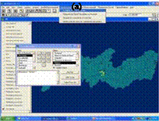 |
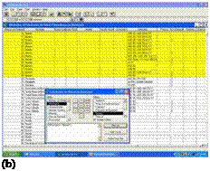 |
Figure 5 — Macro-spatial functionalities of the SIGA-SOL, PV management, PRODEEM installation phase
Figure 6 — Local functionalities of the SIGA-SOL, PV management, (a) PV systems installed in
Ibimirim-PE and (b) the models of modules used
The SIGA SOL planning module was constructed considering these conditionals and the possibility of analyzing the possible combinations of criteria defined by the user for locals for the implantation of new renewable energy systems.
The SIGA SOL functionalities for macro-spatial planning are basically constituted of the following blocks:
IDH and index of non-eletrification;
Areas of exclusion;
CPRM wells;
Aptitude for sugar cane, quantity of produced cane and capacity of electric energy generation with sugar cane bagasse;
Aptitude for castor bean plant, period of planting and biodiesel plants;
Energetic forests;
Wind direction and intensivity, promising area and capacity of electric generation by the wind; Monthly solar irradiation on the horizontal plane and solar irradiation on the collector plane in the month of minimum irradiation.
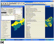
Figure 7 — Local functionalities of SIGA-SOL, PV management, (a) operational situation of the PV system
components installed in Pernambuco and (b) the nearest maintenance centers
Fig. 8 (a) shows the municipalities of Pernambuco that have income per capita less than US$100. The IDH sub-menu permits the obtention of maps with other additional social indicators. The areas of exclusion are defined as indigenous, ecological reserves and special areas of preservation. They are considered areas of exclusion when one wants to localize conventional energy systems or large scale renewable energy systems. In the case of localization of small scale and distributed renewable systems, such areas must be considered as maximum priority. Fig. 8 (b) shows these areas for Pernambuco.
Fig. 9 shows all the subterraneun wells cadastred by CPRM in the state of Pernambuco. A more detailed filtering through a menu permits the choise of some specific aspects as depth or finality. In yellow, for example, wells of depths greater than 30 m.
Fig. 10 shows from top left to bottom the aptitude of sugar cane culture in two distinct scenarios: dry and rainy period. On the right, using the same convention to aptitude for castor bean plant. Fig.
11 shows the mean annual wind speed and prevailing direction of winds, on the right. Finally, Fig.
12
 |
shows solar irradiation on the horizontal plane for the months of minimim occurance (July) and maximum (November) for the state of Pernambuco.
(b)
Figure 8 — (a) Municipalities of Pernambuco with income per capita less than US$ 100 and (b) areas of
exclusion
1.1. Model structure
There are in general two possible ways to describe the thermal behaviour of a heat exchanger considering its geometry. The first one is to (numerically) solve heat transfer equations using finite element or volume methods, e. g. in FLUENT. However, these models require much computing effort and are, therefore, not appropriate for an optimization of the whole heat exchanger configuration. Depending on the optimization algorithm and the complexity of a problem, several thousand calculations can be required. The second way is to use empirical heat transfer correlations
gained from experimental investigations. Models based on empirical correlations require little computing effort, but usually have higher inaccuracies than those using finite element methods.
The model presented here (in the following simply referred to as “the model”) uses empirical heat transfer correlations. It is based on the detailed cooling coil model Type1223new[6] of the ASHRAE[7] HVAC Secondary Toolkit [3, 4], which separately considers wet and dry parts of the heat exchanger surface. Thus, the model accounts possible condensation of vapour[8] on parts or even all over the heat exchanger surface, if the surface temperature is below the air dew point temperature. In comparison to Type1223new, other heat transfer correlations have been implemented. Furthermore, pressure drops on both water and air sides are accounted and the model uses temperature-depending physical water and air properties, evaluated at the mean flow temperature, instead of constant values.
The interconnection of subsystems is done via simple EQUATION blocks acting as interfaces. They provide all needed inputs of the components collected within a subsystem and vice versa the outputs needed by connected subsystems or components. By using EQUATION pairs as input and output interfaces, variables can be transferred without a visual link between a pair (see also Fig. 3 in section 2.2). As a result the possibility of replacing subsystems without deleting or reconfiguring any visual connection in SIMULATION STUDIO is given. The principle is based on the fact that variables defined in equations can be transferred to components or other equations without linking them visually. Furthermore, in SIMULATION STUDIO outputs from components used within an equation must be defined as auxiliary variables on the left of the dialog window of an EQUATION block[12]. These auxiliary variables only appear in the graphical representation but they are not written to the input file of TRNSYS itself. Therefore, they can have the same names as the “real” variables (see Fig. 4). For the example in Fig. 4 the following section will be written to the TRNSYS input file:
EQUATIONS 2 "Inputs-right" input_T_in = [UNIT No., OUTPUT No.] input_mdot_in = [UNIT No., OUTPUT No.]
EQUATIONS 2 "Inputs-left"
Tin = input T in mdot in = input mdot in
In the graphical representation the expression [UNIT No., OUTPUT No.] corresponds to the auxiliary variables on the left of the EQUATION block dialog, where outputs of components can be connected to it (see also right dialog window of Fig. 4). Because of exactly same names of the variables and the auxiliary variables used for the inputs, the transfer within the EQUATION pair in SIMULATION STUDIO is not visible for the user while connecting subsystems to each other (see Fig.
 |
5).
which is located within a subsystem.
 |
The core of the design tool KOLEKTOR 2.2 is a mathematical model of solar flat-plate liquid collector solving one-dimensional heat transfer balances. Solar collector is defined by means of main levels: glazing exterior surface (p1), glazing interior surface (p2), absorber (abs), frame interior surface (z2) and frame exterior surface (z1). These levels are schematically outlined in Fig. 1. Detailed geometrical and physical properties of individual parts of solar collector, climatic and operation parameters are the input parameters of the model. Basic outputs of the model are usable heat gain Qu [W], efficiency ij with respect to reference collector area (gross area AG, aperture area Aa) and output heat transfer fluid temperature te.
The mathematical model of solar collector consists of external energy balance of absorber (heat transfer from absorber surface to ambient environment) and internal energy balance of absorber (heat transfer from absorber surface into heat transfer fluid). Model solves the energy balance of the solar collector under steady-state conditions according to principle Hottel-Whillier equation for usable heat gain
Qu = AaFR [ — U(tin — ta )]
Through the external energy balance of absorber (see Fig. 2) the heat transfer by radiation and by natural convection in the air gap between absorber surface and glazing (event. frame), heat conduction through glazing (event. frame) and heat transfer by convection and radiation from external glazing (event. frame) surface to ambient is solved. To calculate the heat transfer coefficients properly, temperatures for principal collector levels should be known, but on the other side the temperature distribution in the collector is dependent on the heat transfer coefficients values. Therefore, external energy balance of absorber is solved in an iteration loop starting from first temperature estimate for each main level based on given input temperature tin and ambient temperature ta. External balance loop yields in overall collector heat loss coefficient U [W/m2.K].
|
Internal energy balance of absorber assess the heat transfer from the absorber surface into heat transfer fluid provided by fin heat conduction, by heat conduction through the bond between absorber and pipes and by forced convection from pipe internal surface to fluid. Internal balance results in determination of collector efficiency factor F’ [-] and collector heat removal factor FR on the basis of input parameters, operational and climatic conditions and results from external balance. Main outputs from internal balance are output fluid temperature te, mean heat transfer fluid temperature tm and particularly absorber temperature tabs, which governs the calculations in the external balance. Internal balance proceeds in its own iteration loop with respect to relative dependence between mean fluid temperature tm and forced convection heat transfer coefficients in absorber pipe register.
As both external and internal balances are interdependent, superior iteration loop has been introduced to transfer the results from external balance to internal (overall collector heat loss coefficient U) and from internal balance results to external balance (absorber temperature tabs).
Room’s layout is presented in figure 1. Only South and North fa? ade are glazed, height of room is 3 meters. Dimensions of each room are mentioned below. Toilets and circulation are not heated or cooled.
|
Л |
Offices |
WC |
Л V |
||
|
Circulations |
Л У |
||||
|
Л |
|||||
|
Offices |
Conference rooms |
||||
|
V |
V |
|
11.5 m |
|
108.70 m <——————————————————————— > |
 |
Fig 1. Typical floor of type 1C building [3]
1.1. Other features
Internal gains are computed based on occupancy (maximum value is given between brackets), they include the following list of features. Note that maximum occupancy is fixed as 80 % of value in table 2.
• people (8.75 W/m2 in offices, 32.9 W/m2 in conference room, 0 W in circulations and toilets)
• appliances (15 W/m2 only in offices)
• lighting (18 W/m2 in offices, 12 W/m2 in circulations, 6 W/m2 in toilets)
• fan coil unit ventilators (117 W/Fan coil unit)
Solar protections are also modelled, they are controlled by luminance passing through windows and by occupation. Artificial lighting depends on natural light available for workers [4] , and a correlation is implemented into TRNSYS. Occupancy profile is defined for offices and meeting room [3].